François
-
Posts
489 -
Joined
-
Last visited
Content Type
Profiles
Forums
Events
Gallery
Everything posted by François
-
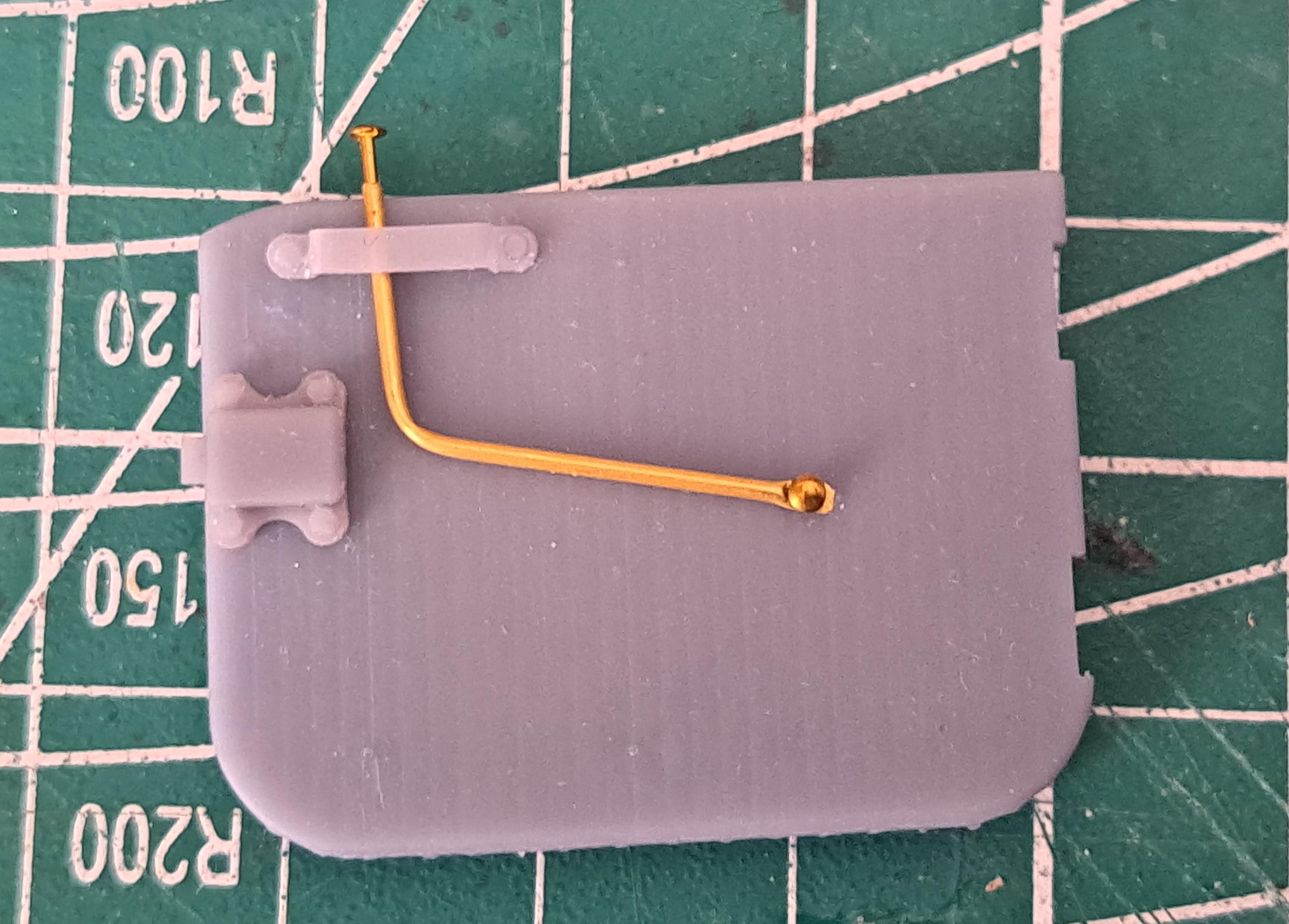
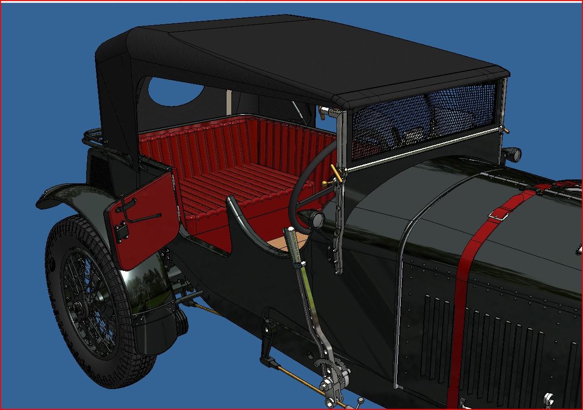
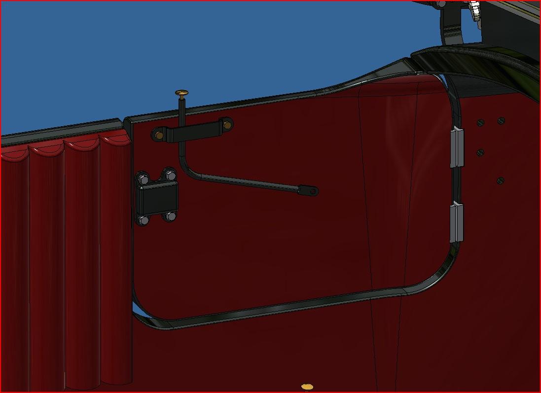
Dry fitting of the left side door latch

-
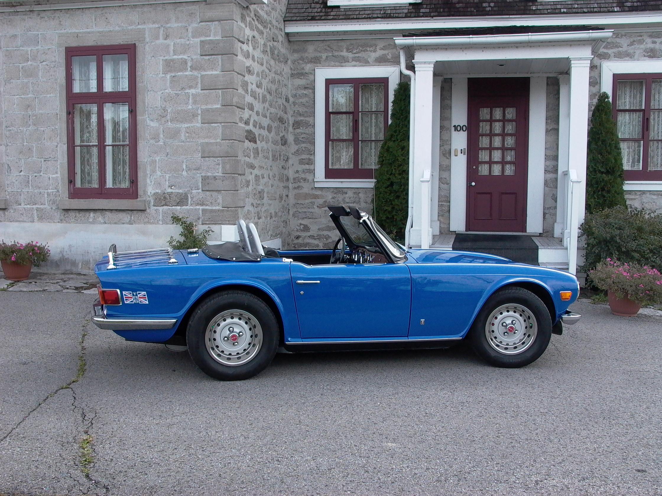
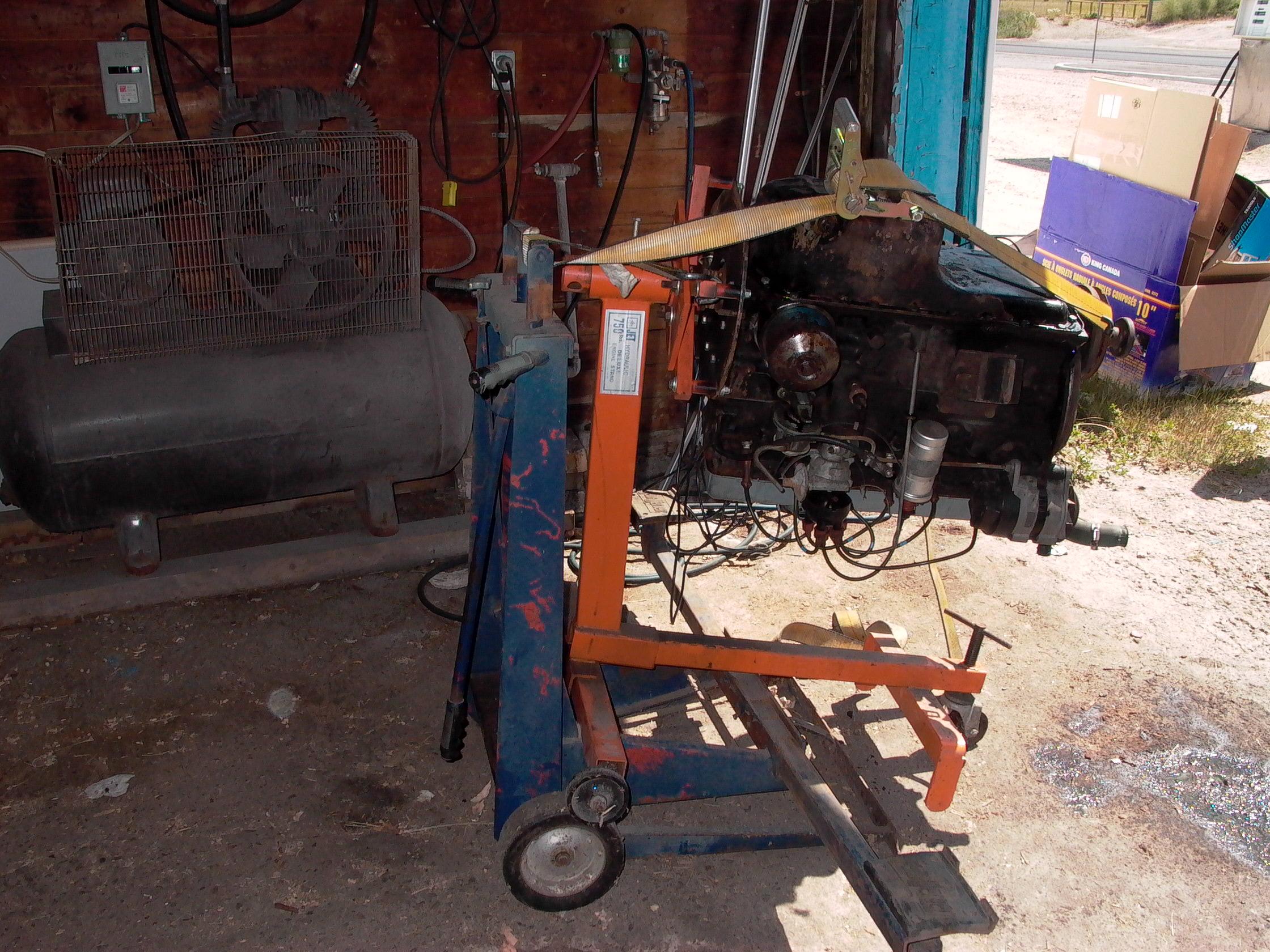
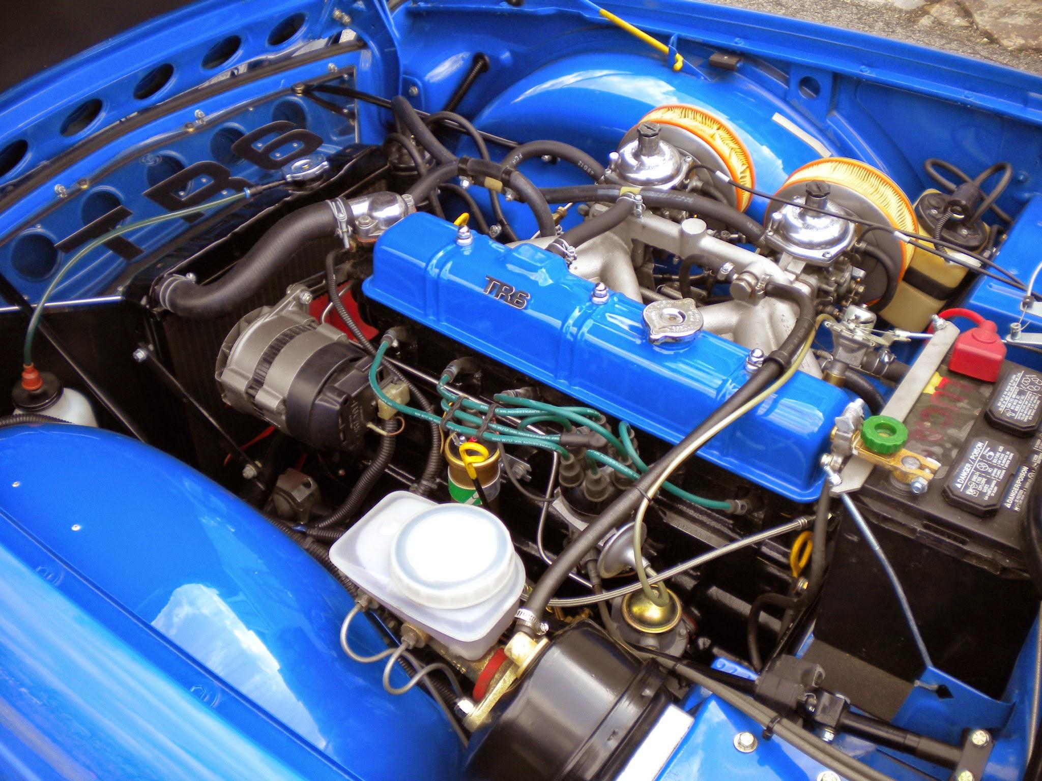
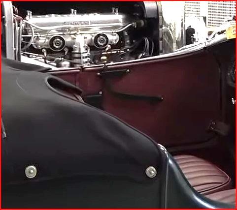
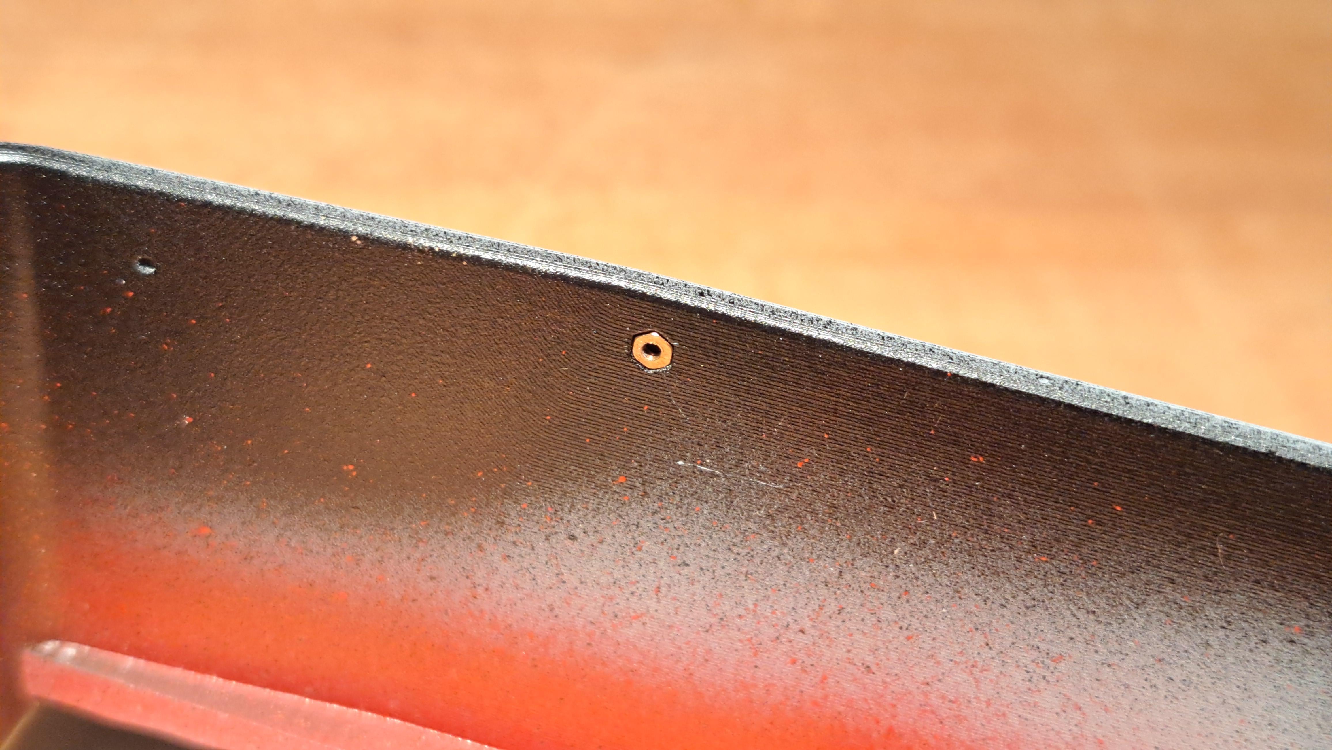
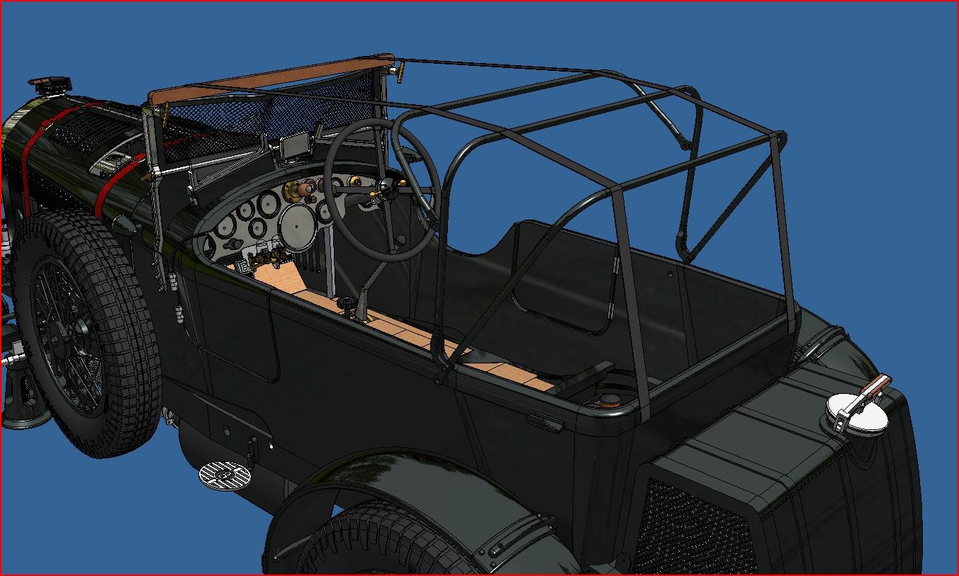
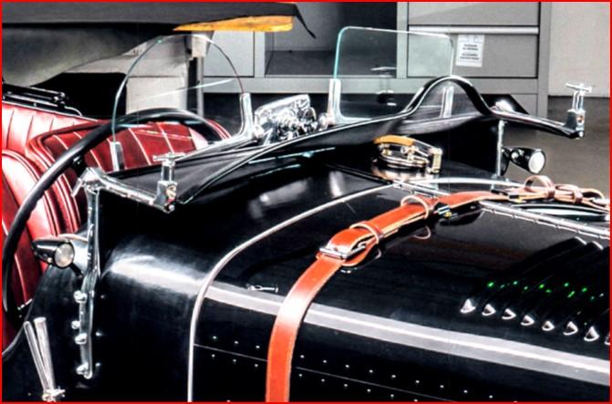
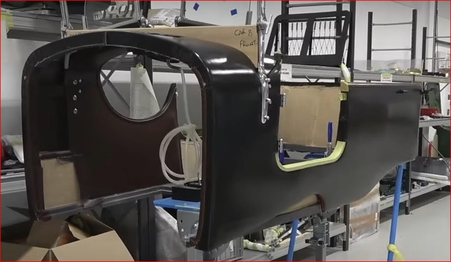
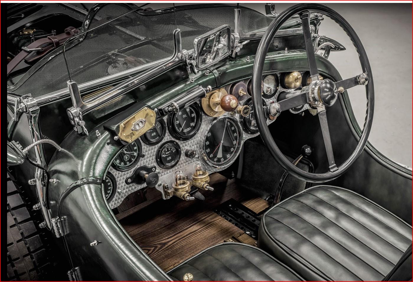
Up date time. I'm slowly advancing the body. I made a full wrapping test using a 4 way stretch fabric. The result was pretty good but installation was very difficult. First, it needs to be glued using a spray on contact ciment. So once on, that is pretty much it. The edges once wrapped around don't hold very well since the material is so stretchy and contrary to leather, it doesn't react to well to ca glue. Here's what it looks like. So I went back on the web to search some more and stumpled on a material called a vinyl car wrap which is basically a vinyl menbrane used to wrap over a car when you want to change color. And it just so happens that a big player in the car wrapping business is about 25 min from my house. There are many positive features to this product. First, it very cheap. 15$ for a 12in x 60in piece, big enough for at least 7 to 8 tries. Second, at only .005in (1/16in scaled up) , it's half the thickness of the 4 way fabric I tried and much more to scale. Third, it has heat activated glue on the back so I can reposition it as much as l like and once satisfied, apply heat to bond. And fourth, it's heat shrinking so once wrapped over the edges, you apply heat and it hucks the edge. I found a piece that is satin black that I think should look pretty good. Here's a test I did on a door I should be wrapping soon. I reprinted a body with all mounting holes in it. It's now primed and ready for wrapping. Since the interior will be upholstered in red leather, I painted certain areas red in case the leather doesn't cover everything. I even incorporated hex nuts to screw in the foldable top frame. here's my body collection so far I found a nice piece of red leather for 5$. It's a bit thicker than l like but I should be able to skive it. I started 3d modeling the interior finishes. I modeled the door latch based on the few pictures I could find. The latch inspiration My 3d model And finally, I made some bending test for the foldable top frame. Here's another comparison shot of my model and the ref car And another video of the running engine because it's just fun to watch. 20240425_120412.mp4 As a side note, I was asked to design and print some parts for a 1/18 scale diecast C8 Corvette. The guy has the real one but his diecast model didn't have the correct wheels, rear spoiler and was missing a few other parts. Here's the real car the wheels I printed And all the parts
-
Yes to both question... this is a british car and they leak from everywhere.
-
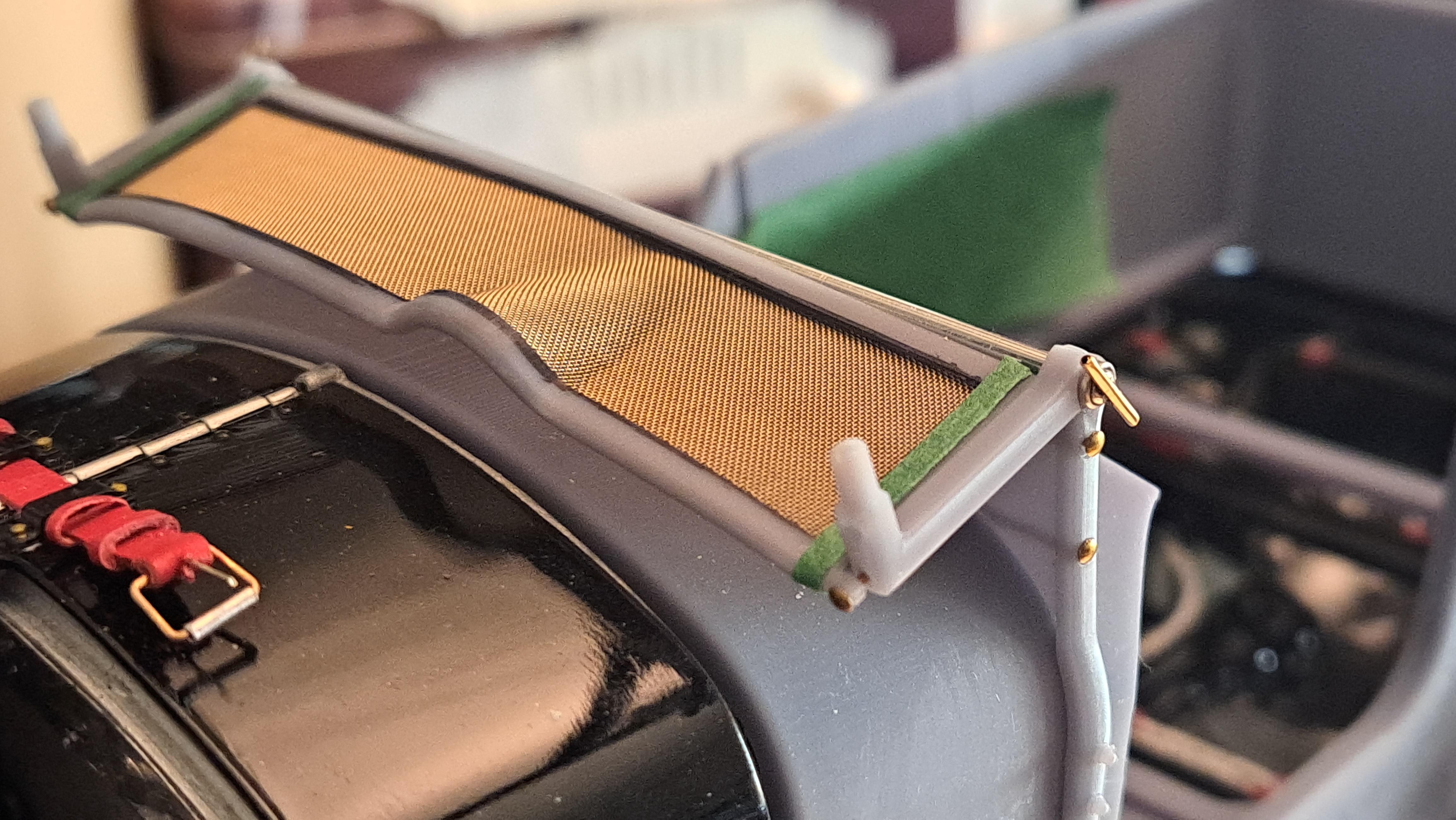
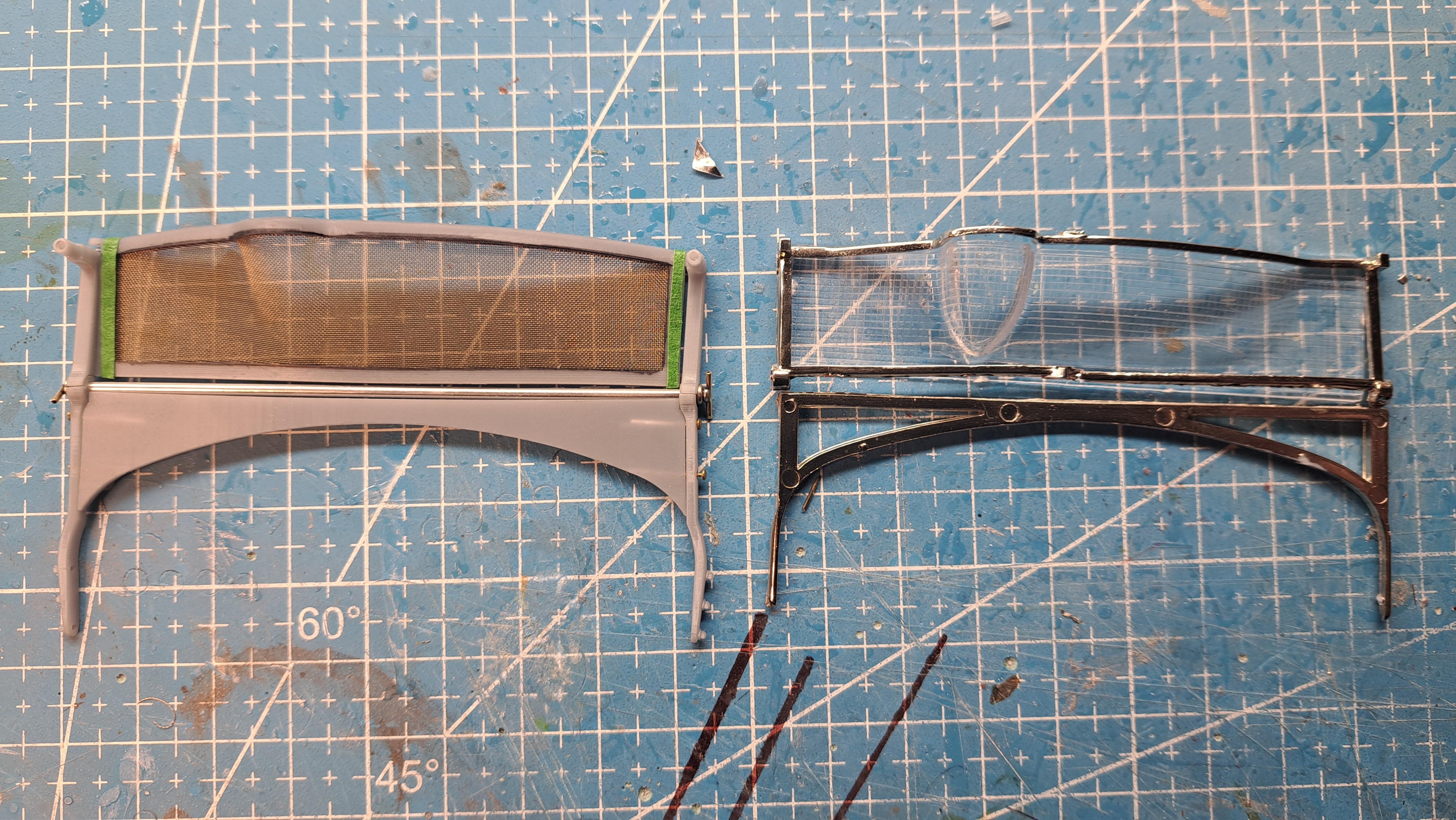
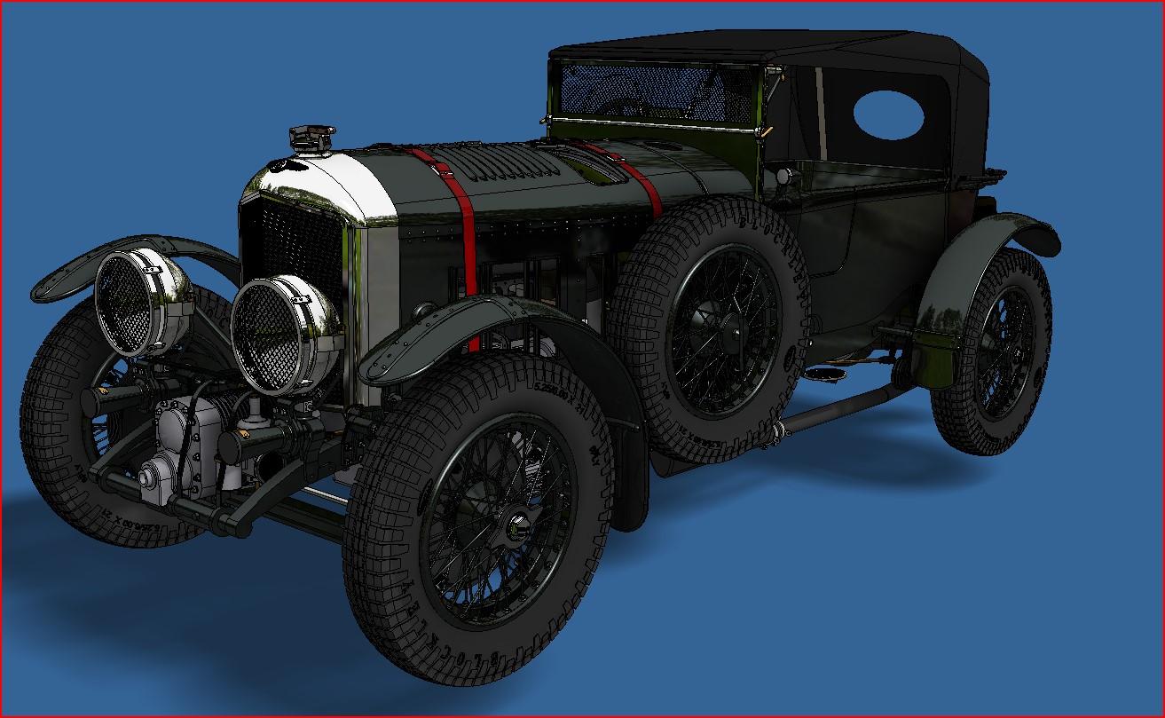
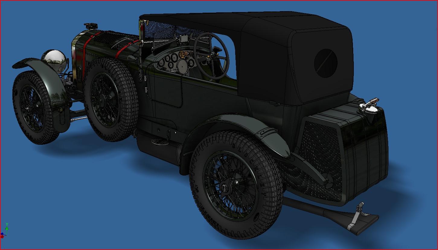
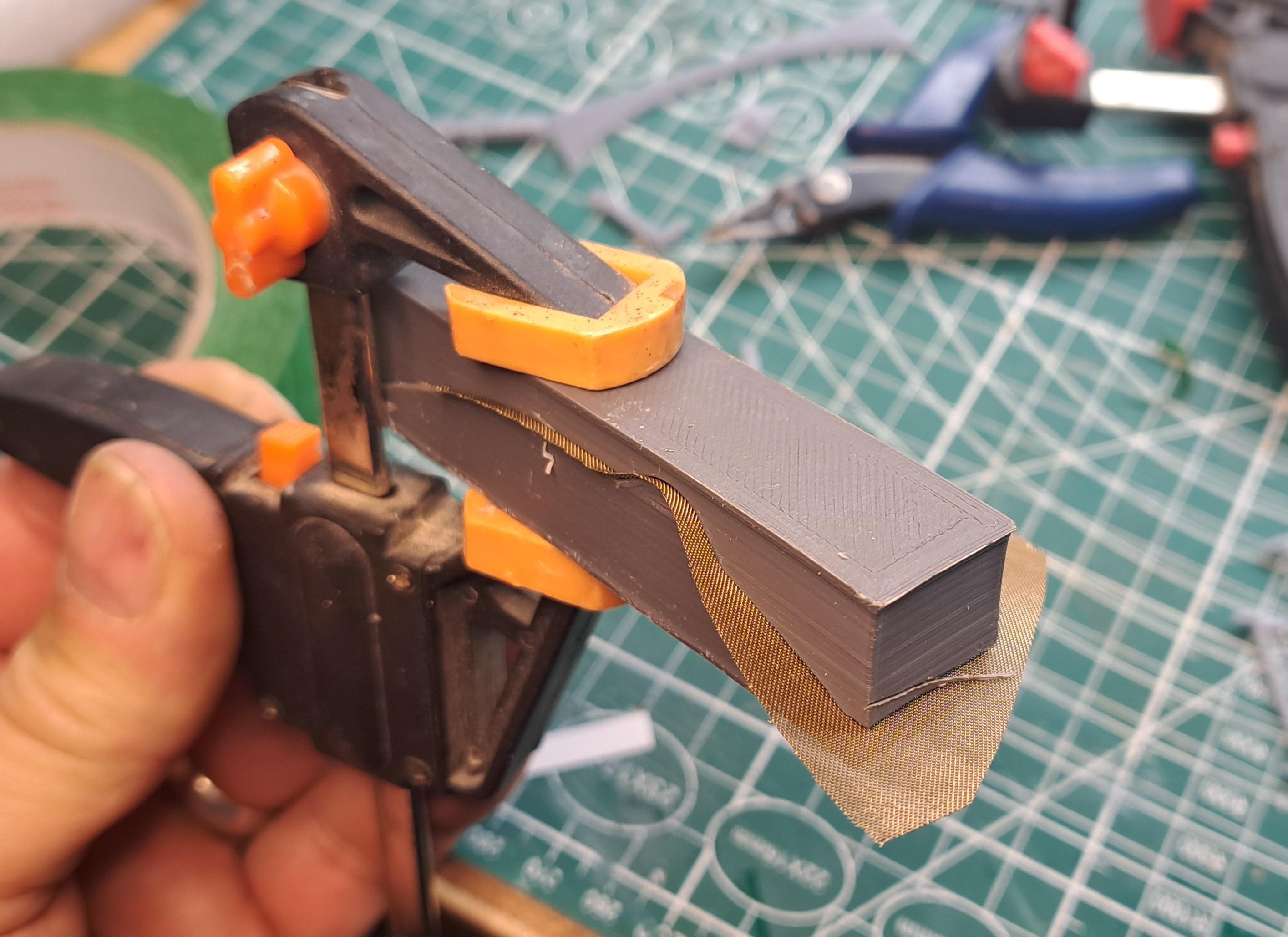
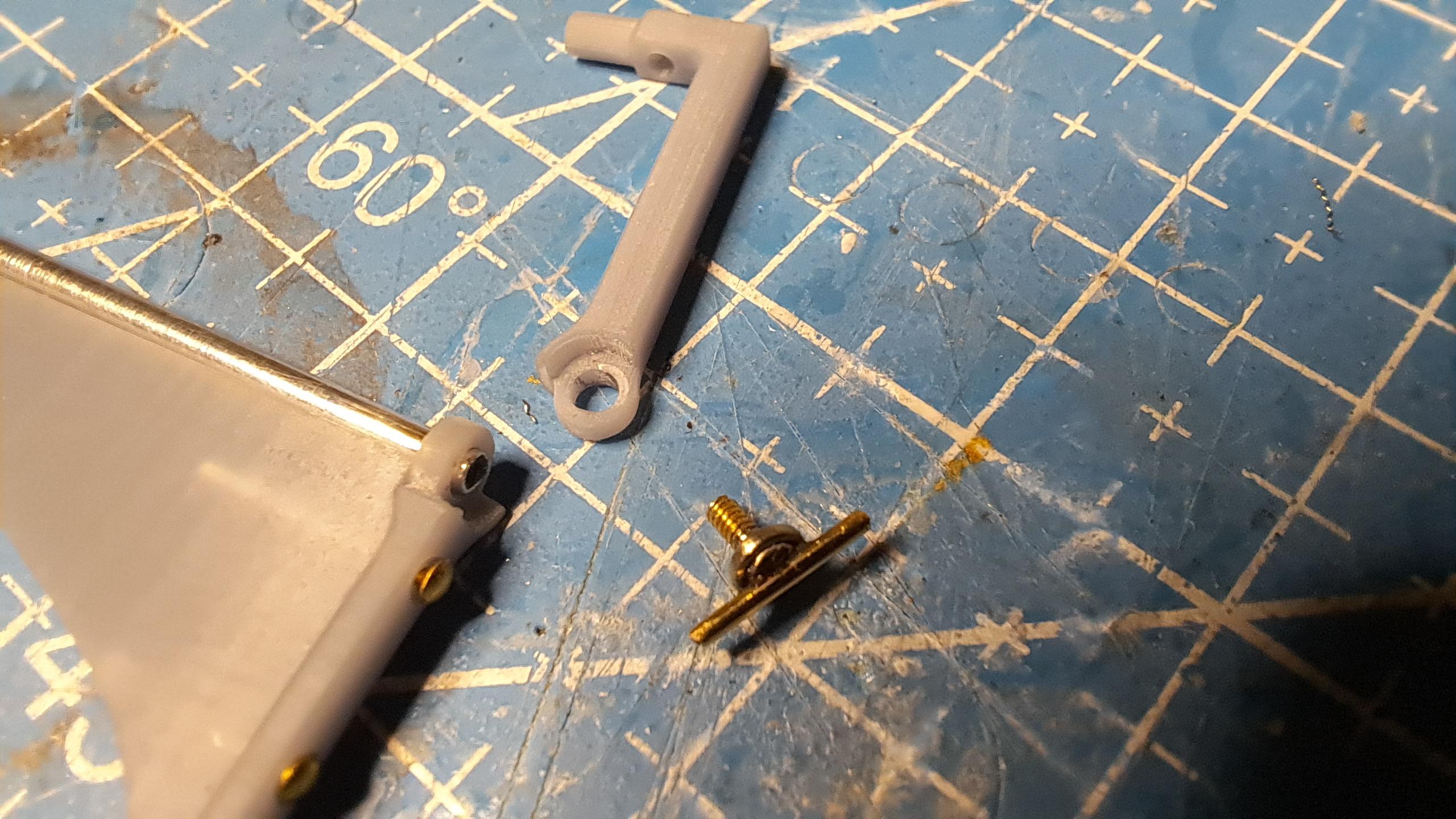
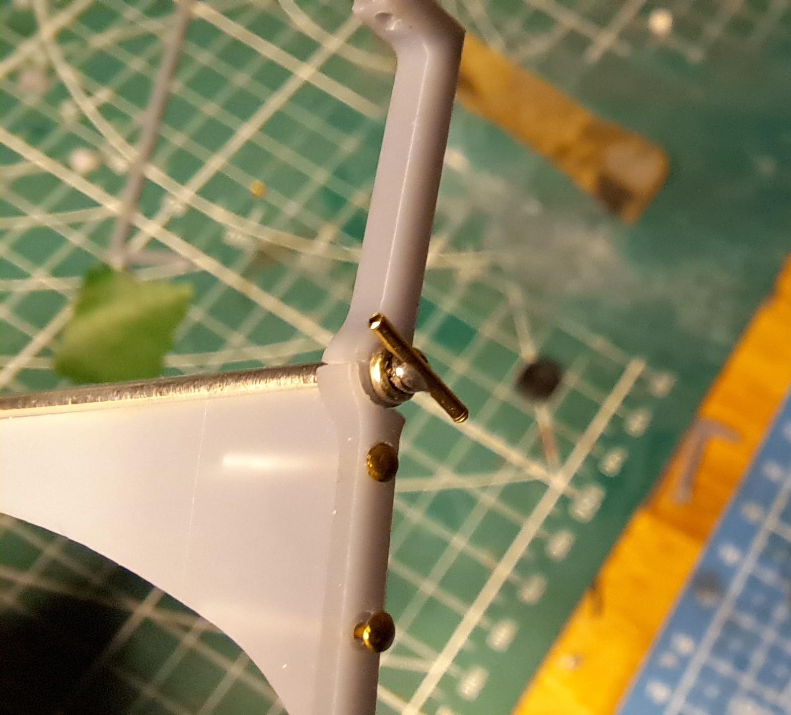
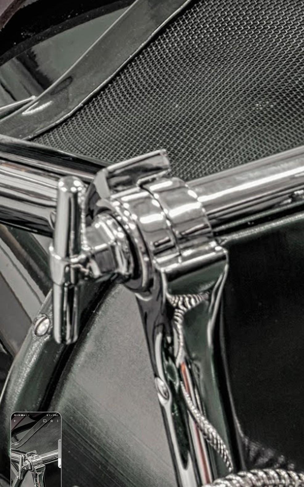
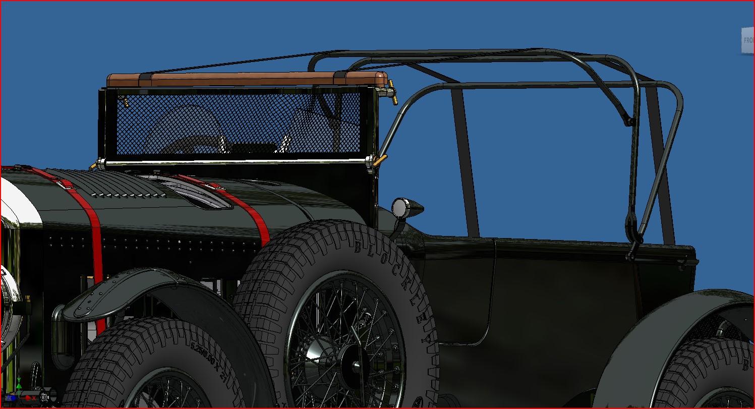
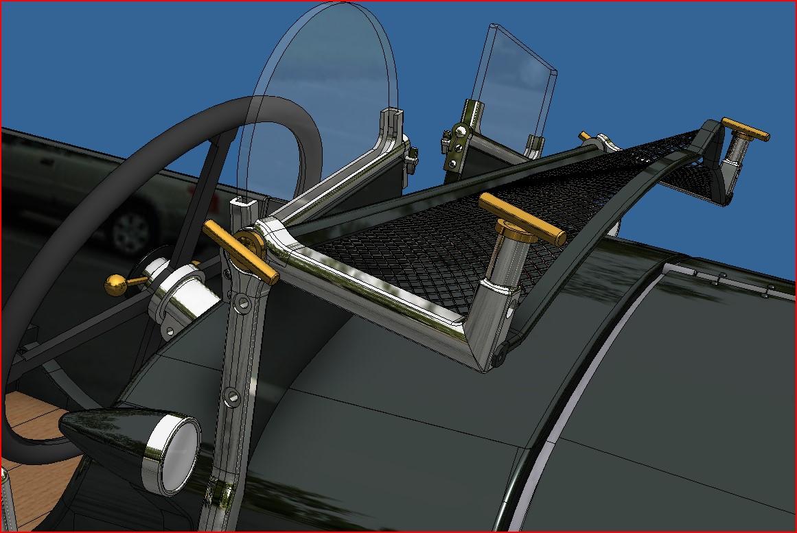
The top is modeled and it was effectively not easy to do. Hopefully I'll be able to do it for real. Here's my 3d model And a real top I've worked hard on printing the different windscreen components and as predicted, some were very tricky to do. I've dry fitted the meshscreen with it's mounting frame and I'm very pleased with the result. The difficulty with the mesh screen was to figure out the proper shape of mesh to cut. Since the mesh is not flat ( it has a fairly prononced bump to clear the oil tank cap), it's shape is not a rectangle but rather a mix of straight and curved line. I tried to determine the shape using good old geometrie but I've been using a 3d cad system for so long the my basic draftman's skills are very rusty. So I took the easy way out and printed a 2 piece male/female press to conform the mesh. All I had to do was to cut the mesh following the contour of the press. I then had a correctly shape mesh that could be inserted in the frame. Easier said than done. It took me about 1 hour but I got it in! Too bad I'll have to disassemble it for paint but I know it fits. Here are some pictures. The male/female press The mesh in the press ready yo be trimmed The mesh inserted in the frame Scratch built clamping screws The real one The mesh screen installed in the mounting frame My assembly next to the kit's The aftermath... Next up, the foldable top frame.
-
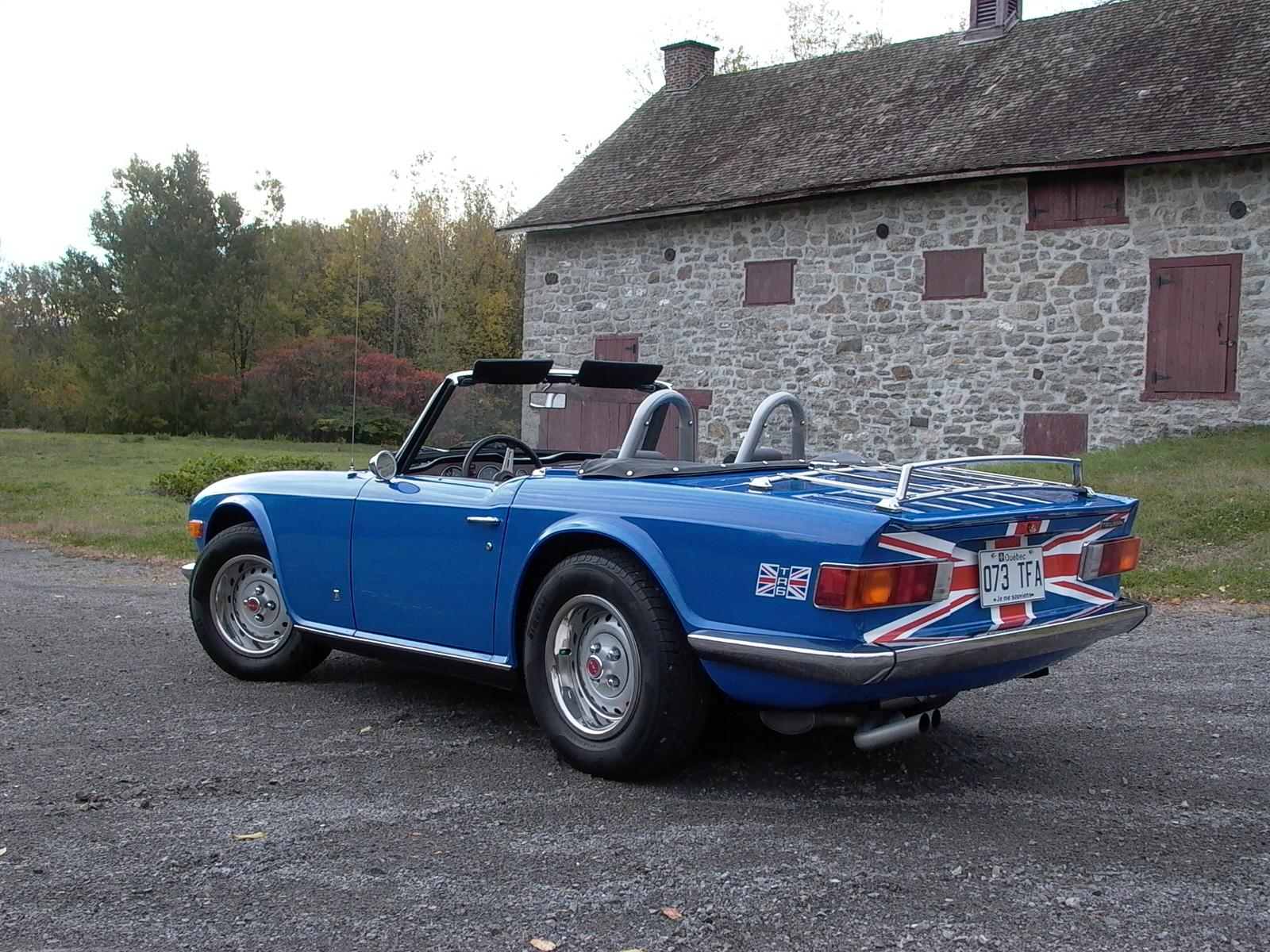
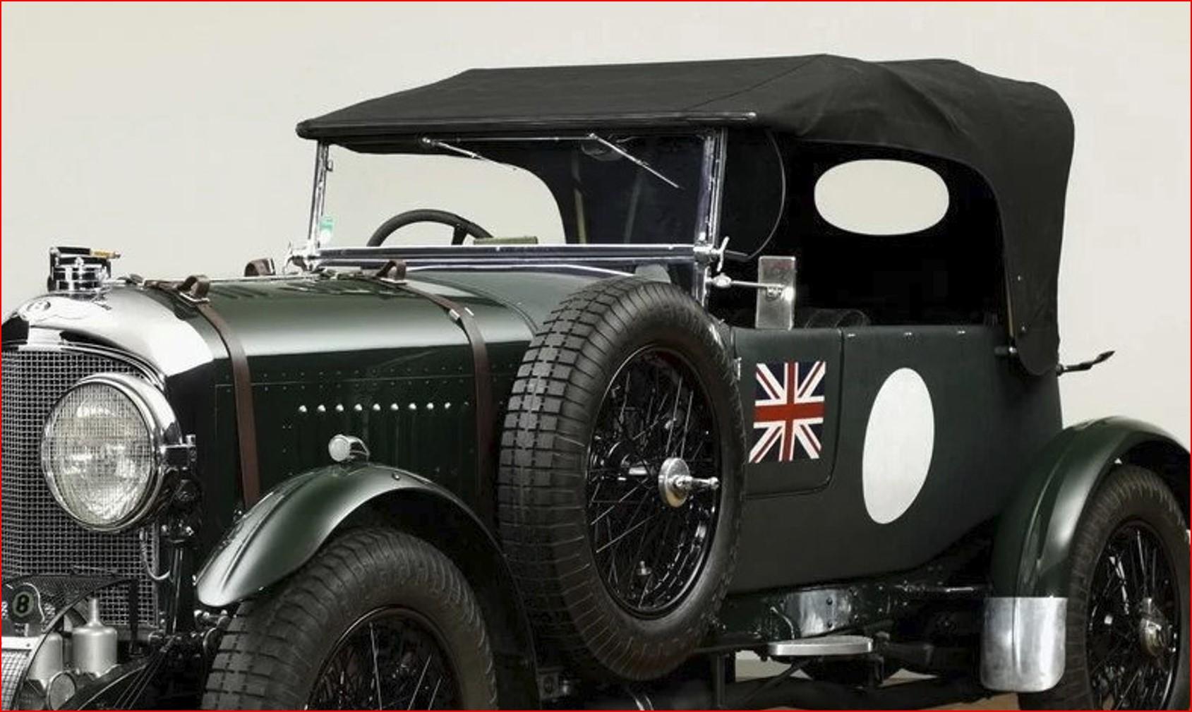
Continued on the body components. Today, I tackled the soft top frame. They are very few ref pictures of the frame and even fewer of a top in place. I could only find one. So there is a lot of "modelers leeway" in the design. Here's the frame so far. And the only pictures of a top up I'll try to 3d model the top itself, not easy to do.
-
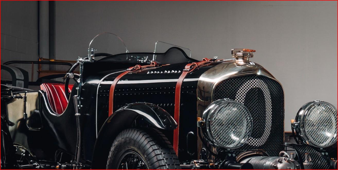
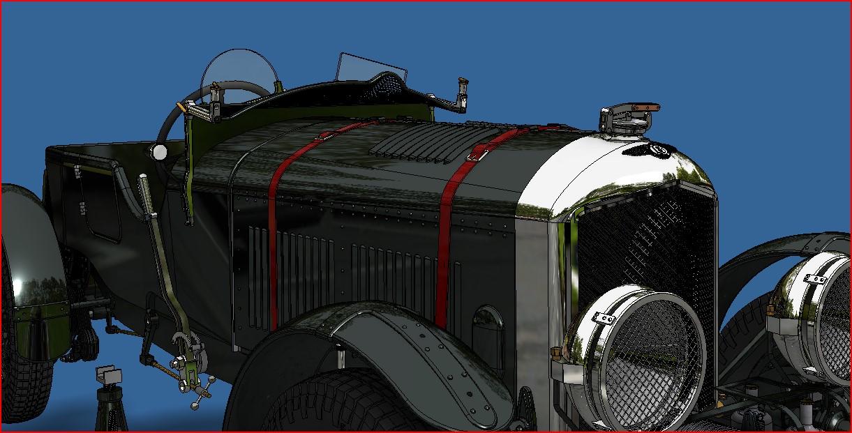
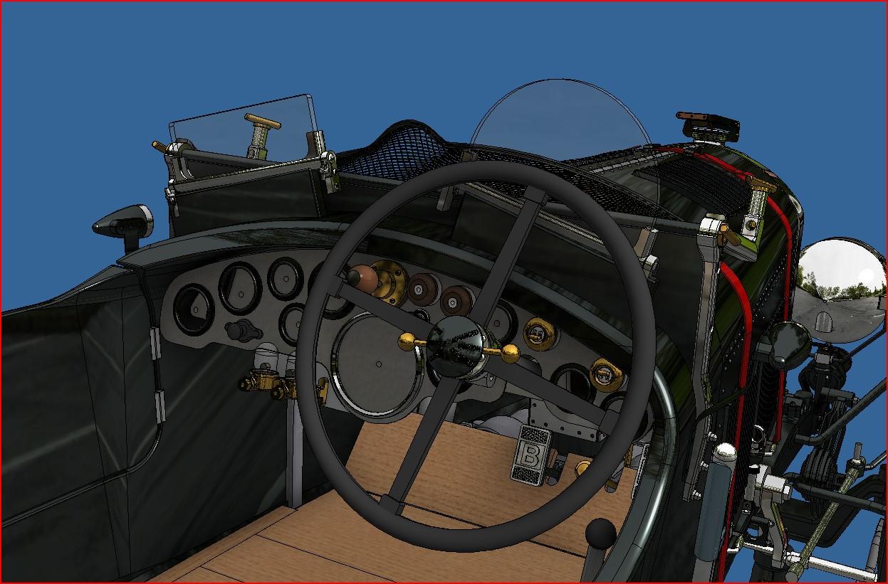
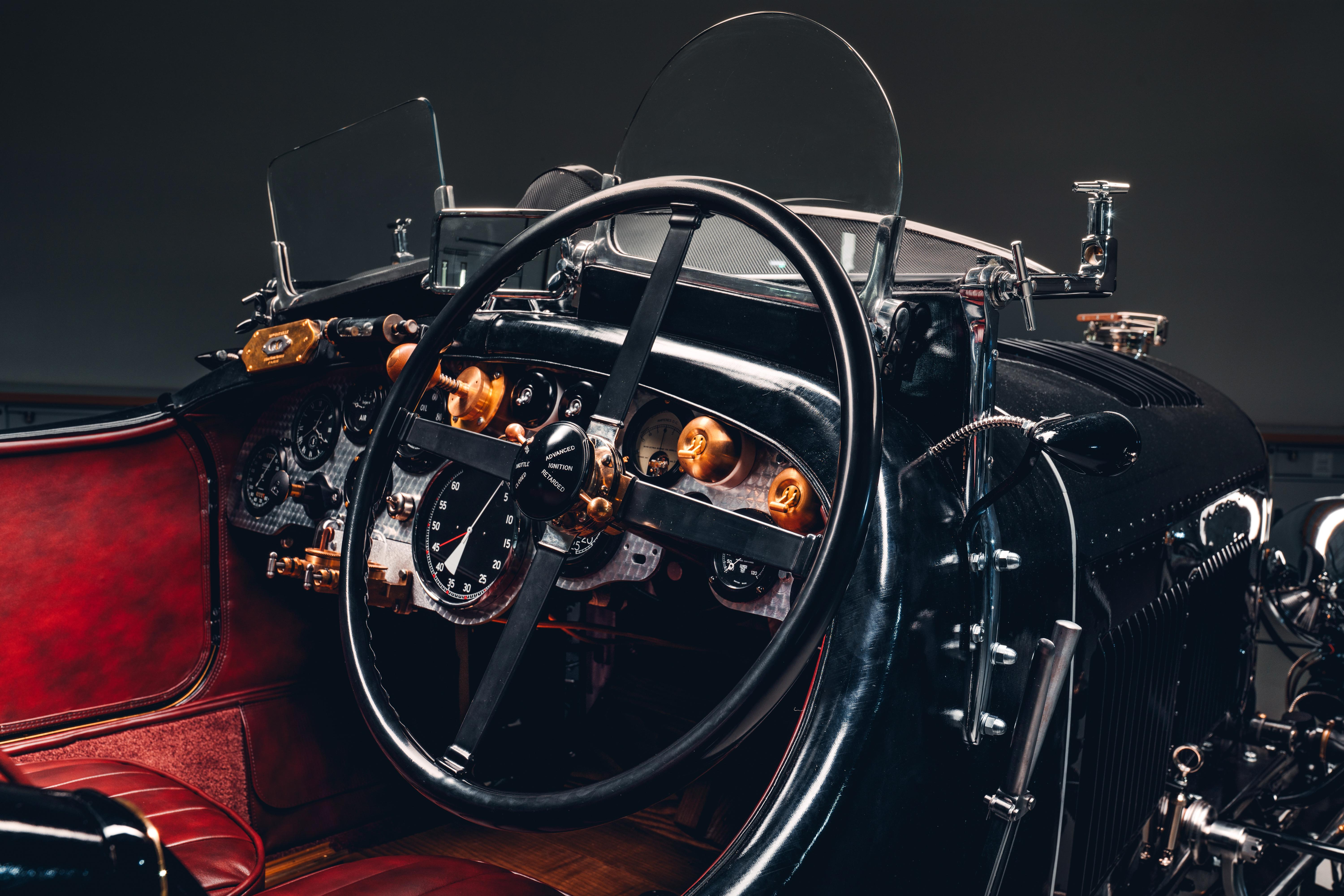
Made good progress on the design of the meshed screen and windshield today. Some of these parts will be interesting to make, especially the meshed screen. Here are some fun shots of the 3d model compared to the real car.
-
Althougt they are not the same model, they are still very nice.
-
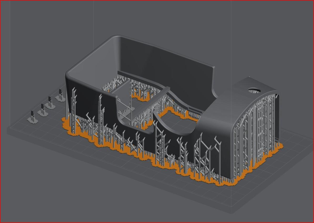
The case is pretty much finished, l'm still waiting for my .5mm electrical wire order to come in to do the lighting. So while I'm waiting, I went back to the model itself. Like I said before, the only thing left in the body. Here's a list of what as to be done 1- reprint a new body with full walls and all missing features (hinge cut-outs, holes to locate mesh screen, visers and soft top frame) 2- design mesh screen and visor mount 3- design soft top frame 4- wrap body with rexine like material (I've done a few test and i think I have a good material) 5- make leather coverded seats 6- make all interior panel and fittings 7- make dashboard 8- make wood floor boards .... So as you can see, I'm closer to the end but still have lots to do. On May 10th, lt will make 1 year since I started this project, and I see at least another 3 months to complete. Here are a few pictures of what as been done so far. I did some wrapping test using the kit's body. I tried a very thin black leather on the passager side and a 4 way sstretch glossy fabric on the drivers side. Althougt the leather is nice and very easy to work with, I find that the glossy fabric better mimics the rexine. Leather Glossy fabric actual rexine coverded body I've test printed a new body. It has exactly the same shape and size as my other printed body except it has full walls. It will make wrapping much easier. And once finished in and out, no one will see the differrnce. Body in slicer app I started modeling the mesh screen mounting brackets The real thing
-
Completed the wire harness on the model and everything work as planned 20240408_083236.mp4 20240408_084511.mp4
-
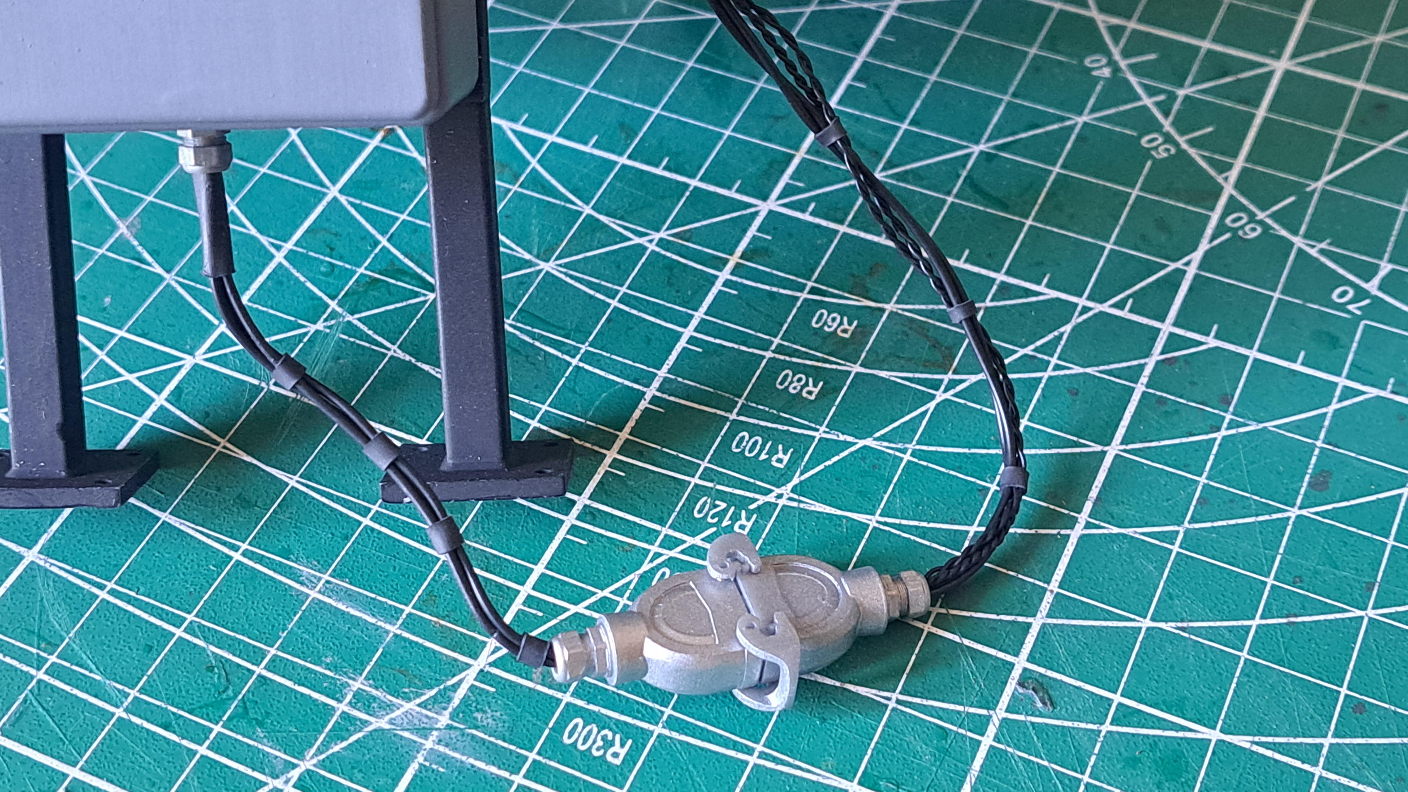
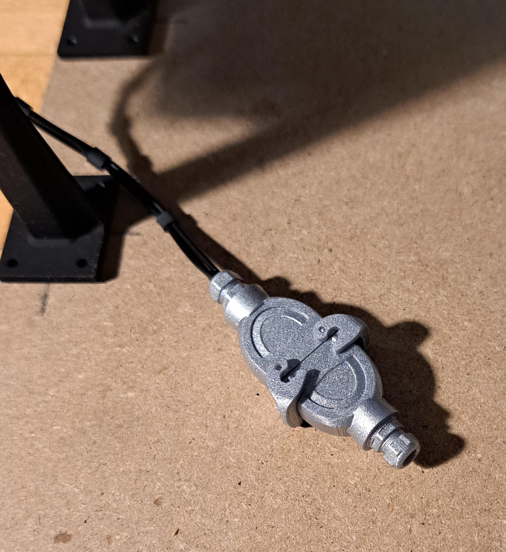
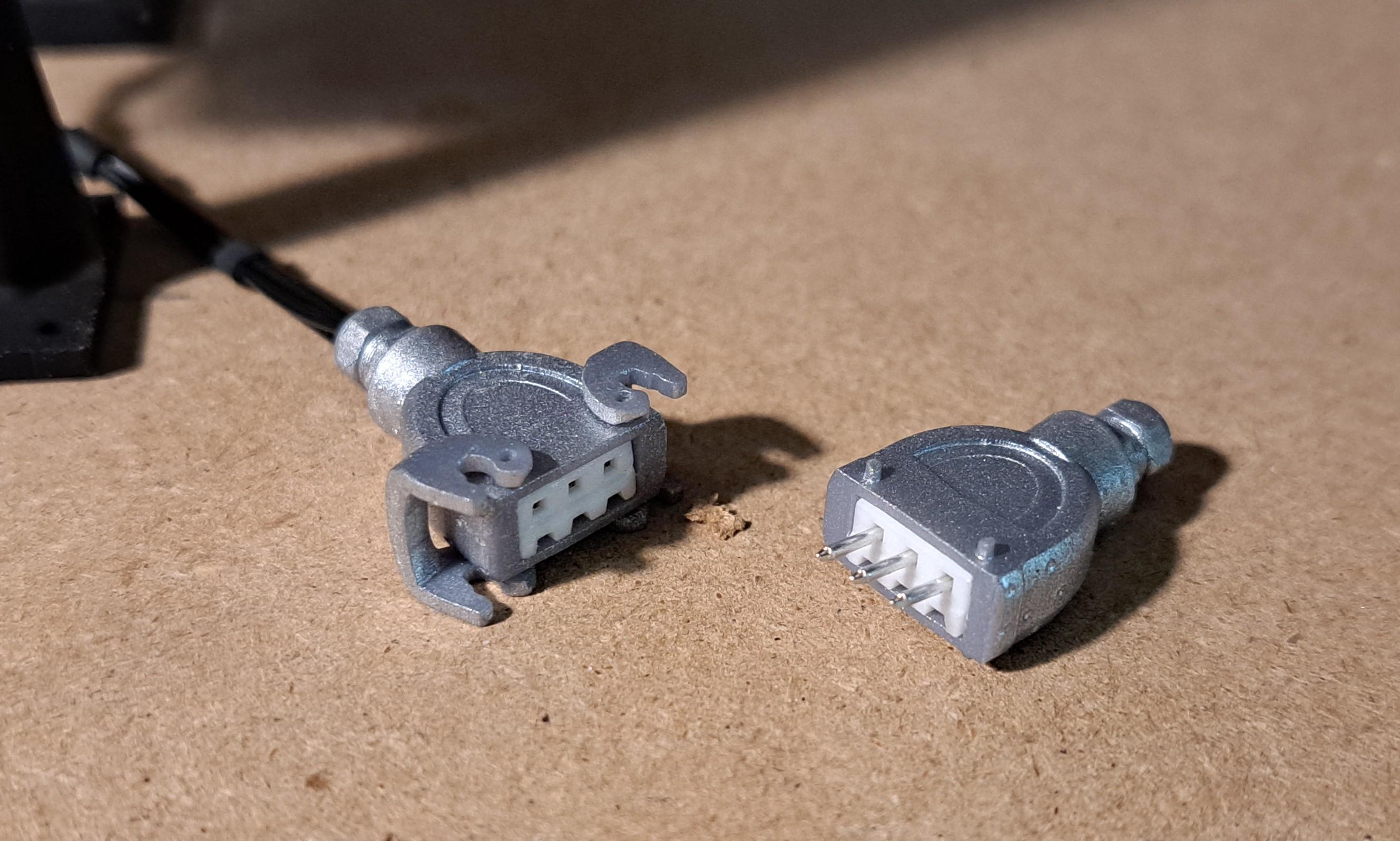
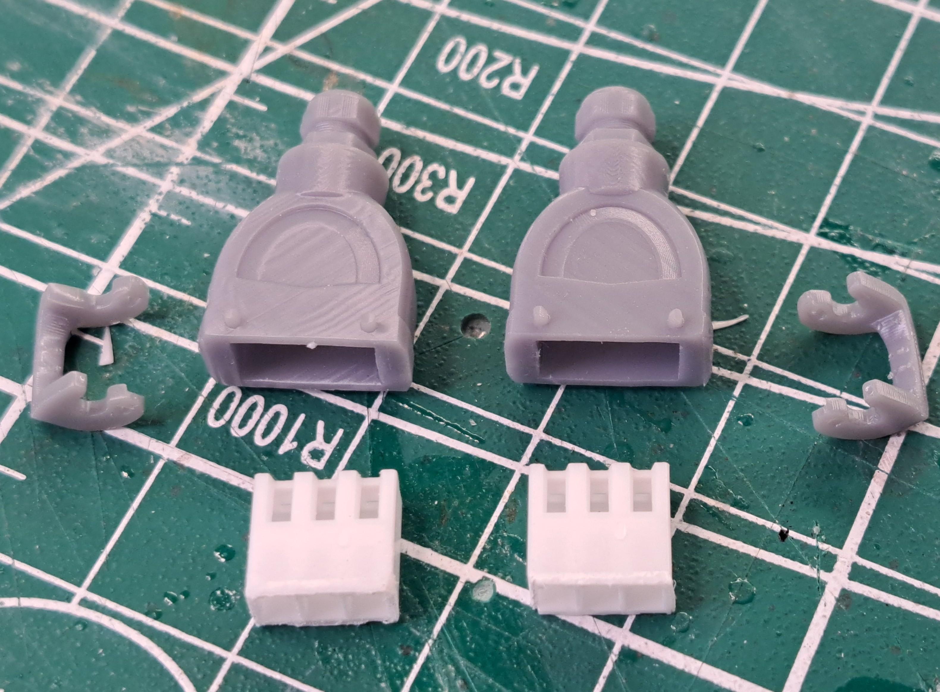
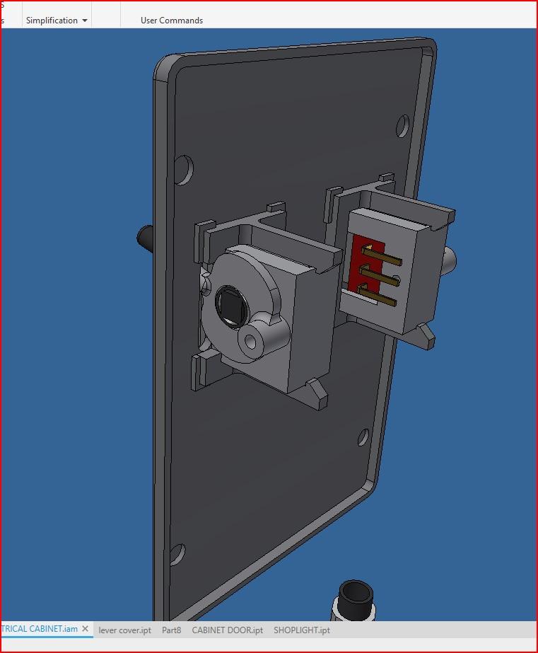
Did a bit more work on the electrical cabinet. The model will be hooked up to this cabinet but I want to be able to unhook it if I need to remove the model from the display case. So I modeled and printed a miniature multi pin connector complete with locking latchs. I've used these type of connectors many time on machines when it was necessary to separate one piece of equipement from another, exactly what I want to do here. All connections to the battery box and switchs are done Here's the cable connector on the cabinet And the multi pin connector
-
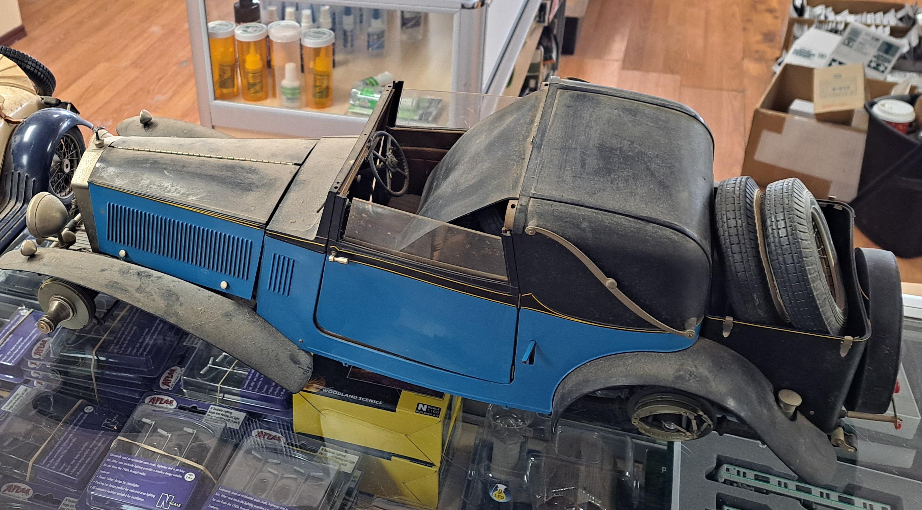
Hello everyone, For those of you that follow my Bentley Blower build, you know that, althought not yet finished, I'm a lot closer to the end that I was whrn I started about one year ago. That's why I'm starting the ground work for my next project, a full restoration of an already built Pocher rolls royce phantom ii. I recently found this car at my local hobby shop. I don't know who built it or when, all I know is that it's in a very bad state. So here's what I would like to do with it. 1- complet dismantle and cleaning of every usable parts 2- 3d model and print (or scratch build) any part destroyed during dismantling. I'm expecting there will be many 3- 3d model and print any parts that do not look like the real ones 4- like many of you know, Pocher cars have working engine pistons and crank which is a steep in the right direction. I'd like to go further by incorporating a small gearmotor to electricaly drive the motor. I'd would also like to drive the rear wheel also. Another aspect of the engine that in lacking is the valve train. Althougt nicely detailed, it is static. I would like to have a working valve train driven from the engine. In order to properly do this, I need to find some pictures, drawings, exploded views... of the 7.7 liter straight 6 engine that was in the car. If anyone has this kind of info, please let me know. 5- a full interior up date 6- wiring for head lights, brake lights, flashers 7- maybe a redesign of the bodywork to give it a slightly different look 8- transform it into a full rag top version Here are a few pictures of the car as found. More to come later this year.
-
Here is another example of things I can design and print. As you can see, it's not just for modeling. A button cell box (casing)
-
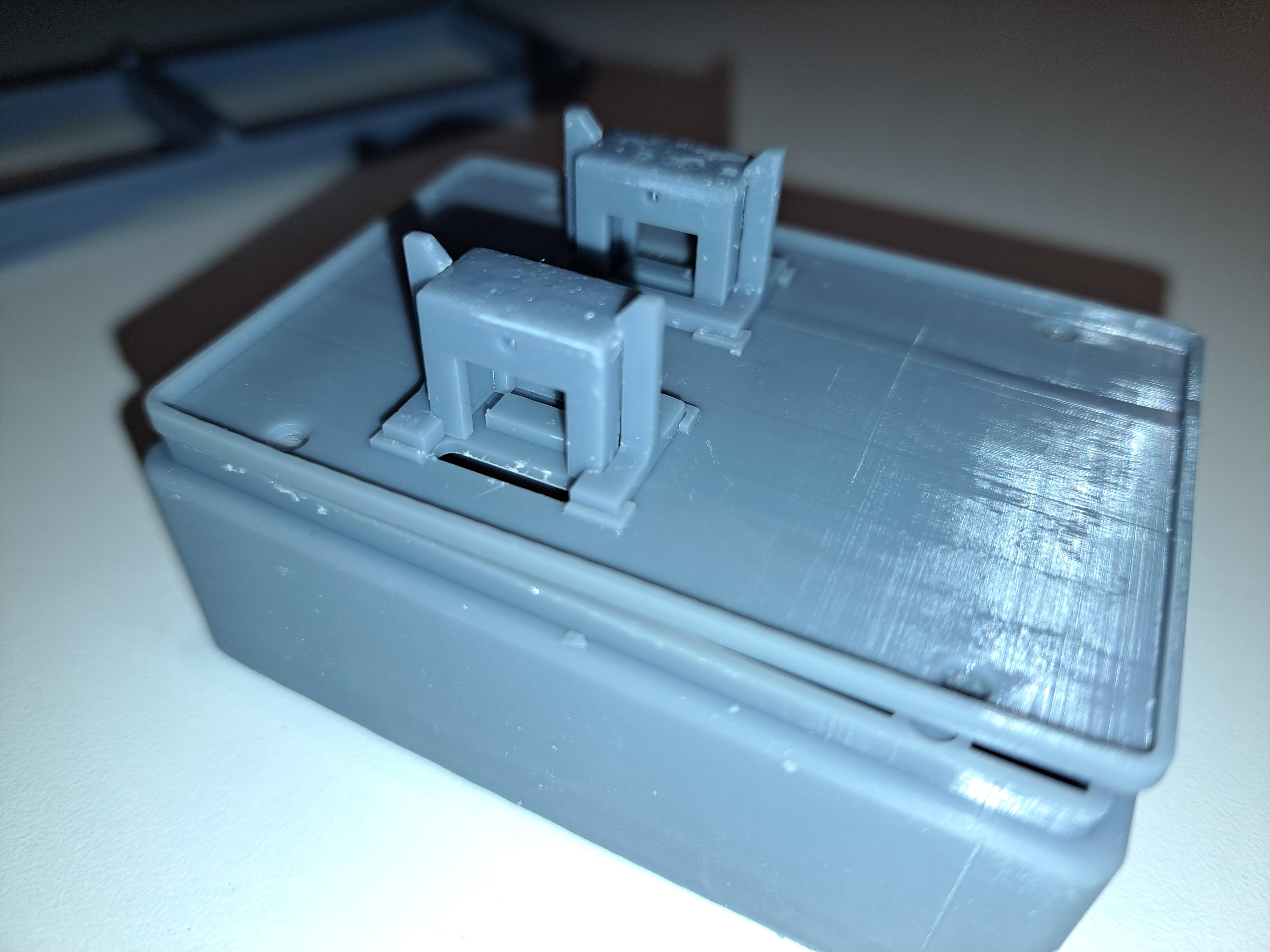
I started the final assembly of the display case, so far so good! I'm waiting for some .5mm dia electrical wire so while I'm waiting, i'm doing the control box wiring. I had a small CR 2032 button cell box but i'd rather use CR 2450 cells which are bigger. So using the inerts of the box I had, I designed a bigger one to suit the bigger cells. Here are a few pictures of the display case so far and the battery box The black one is for the small cells, the clear one I printed And inside the control panel
-
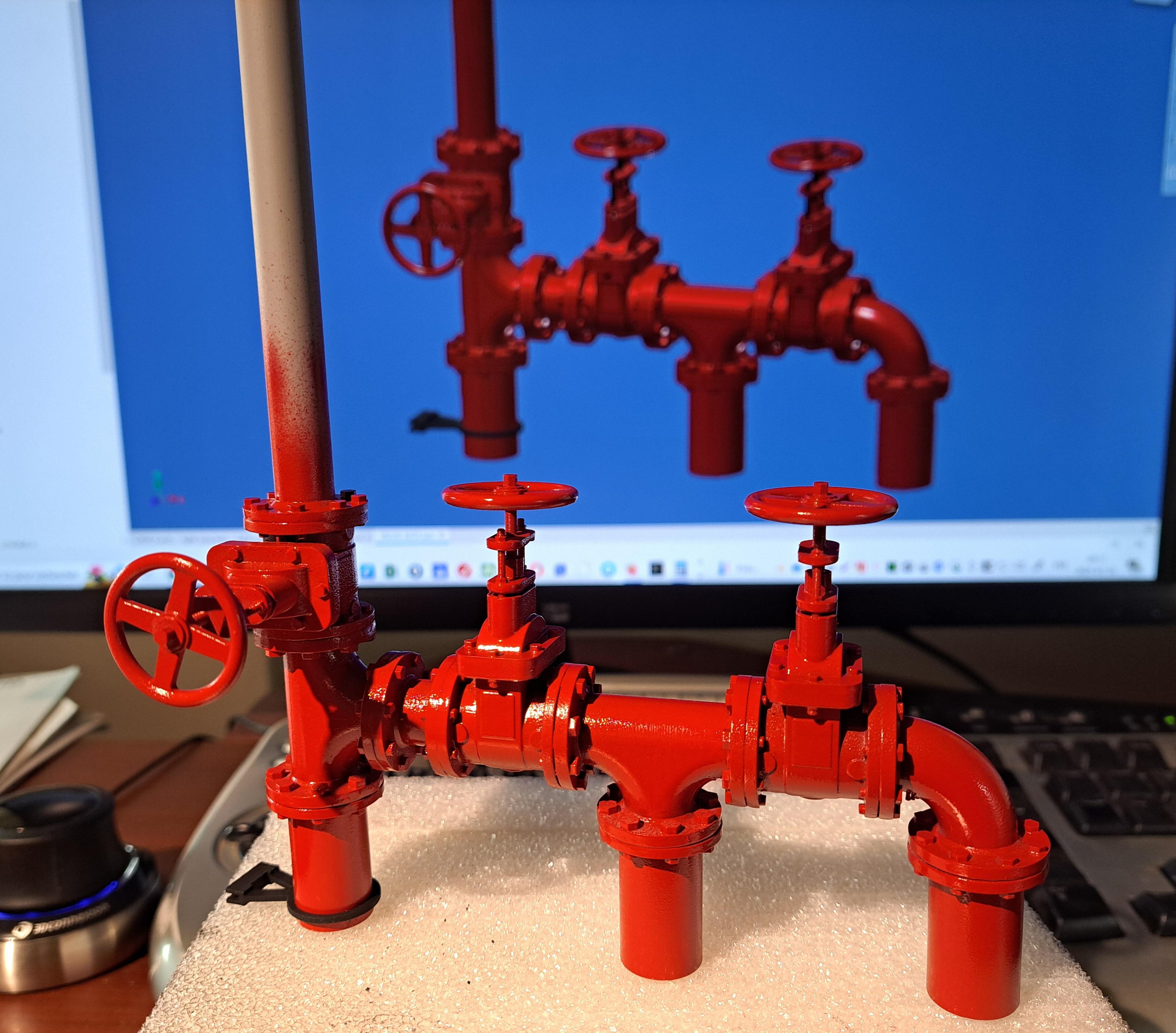
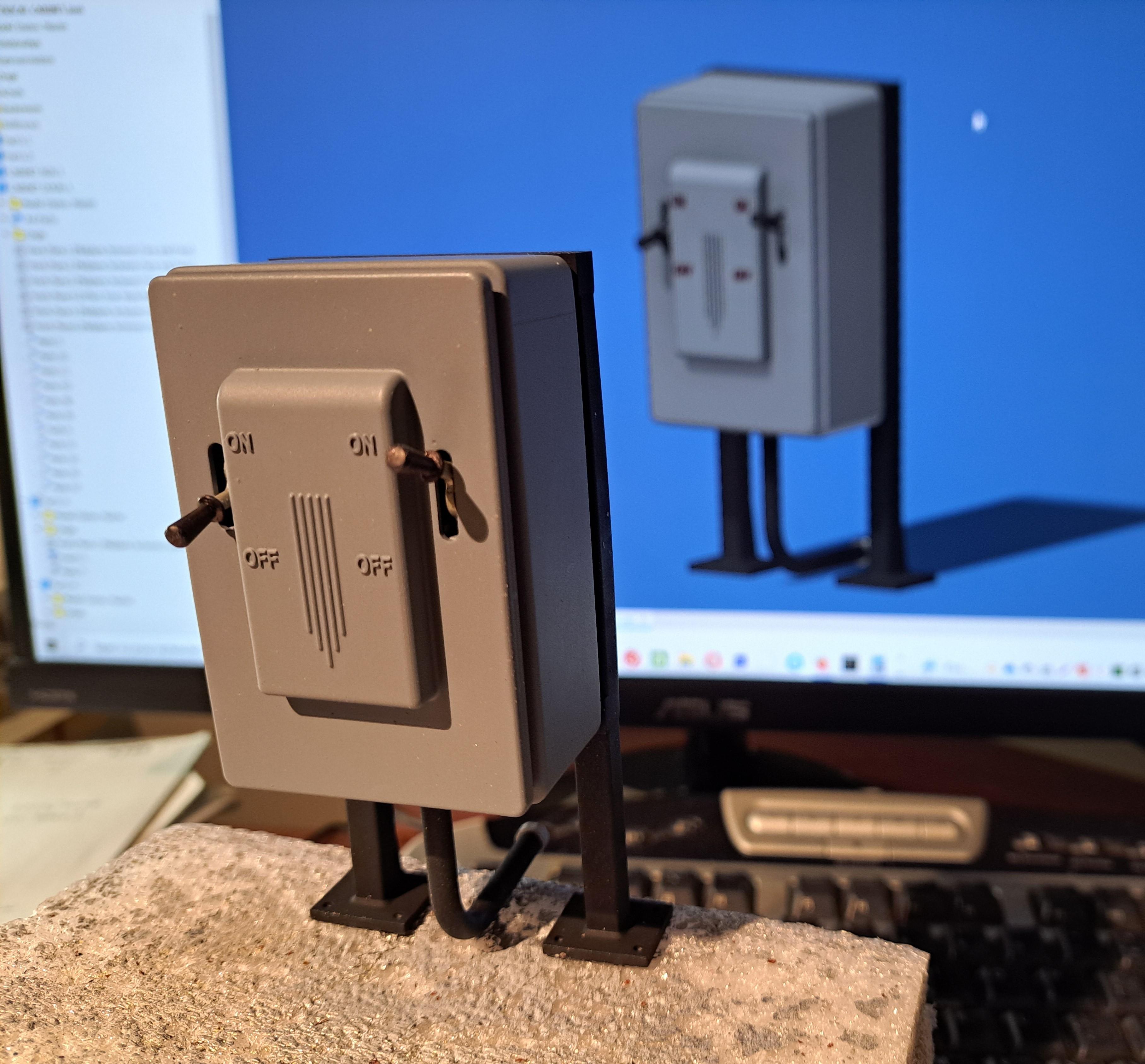
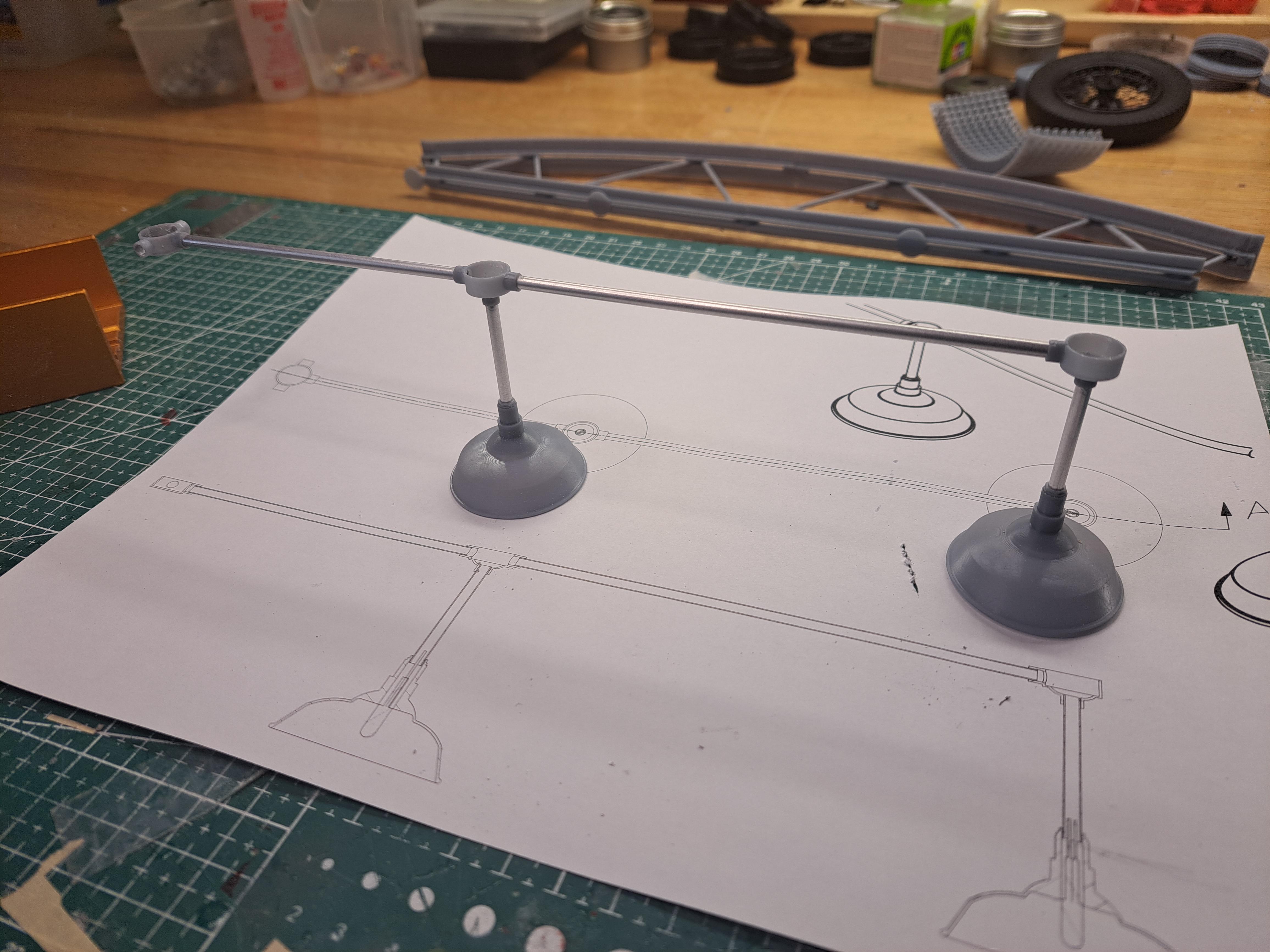
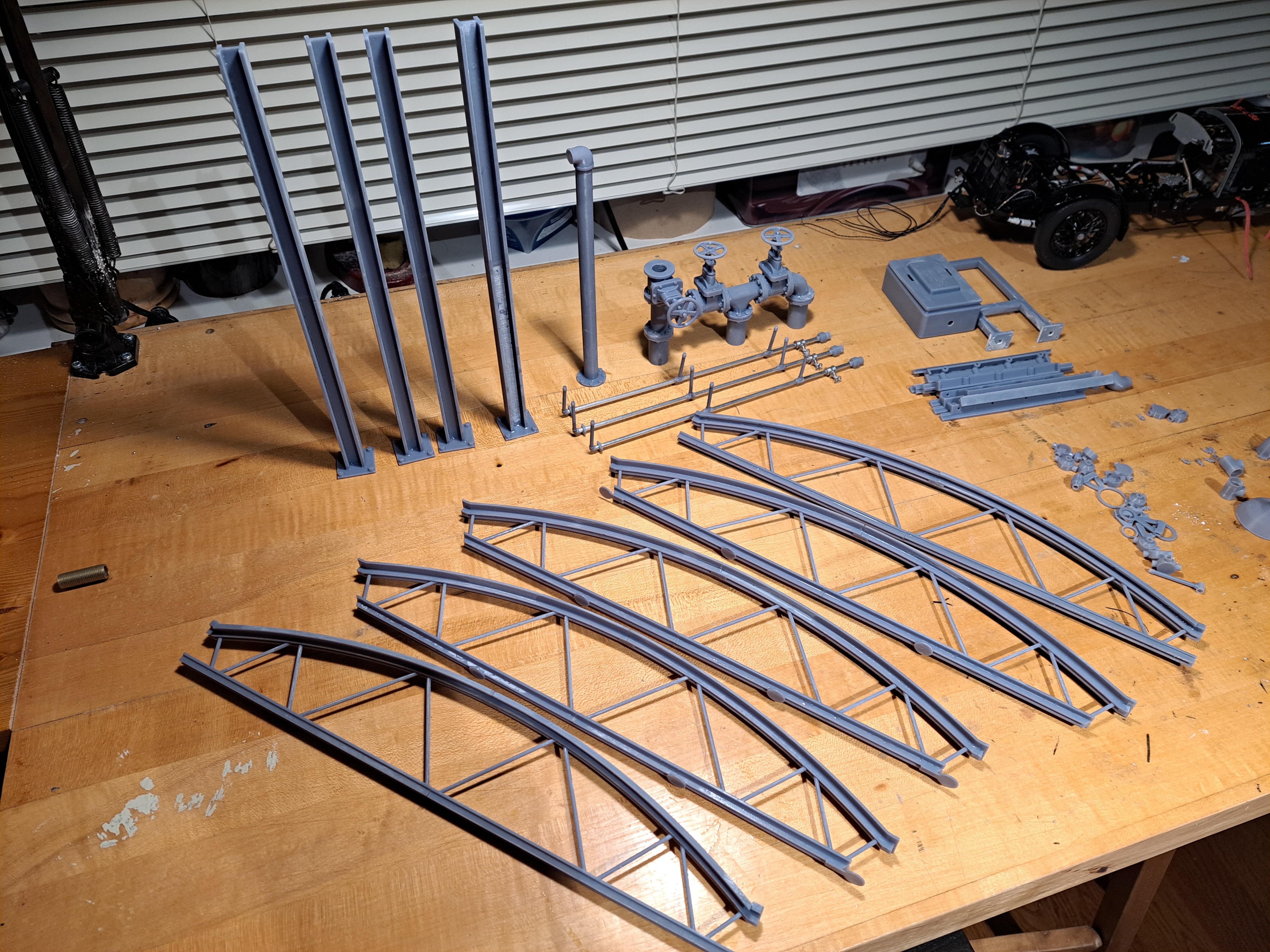
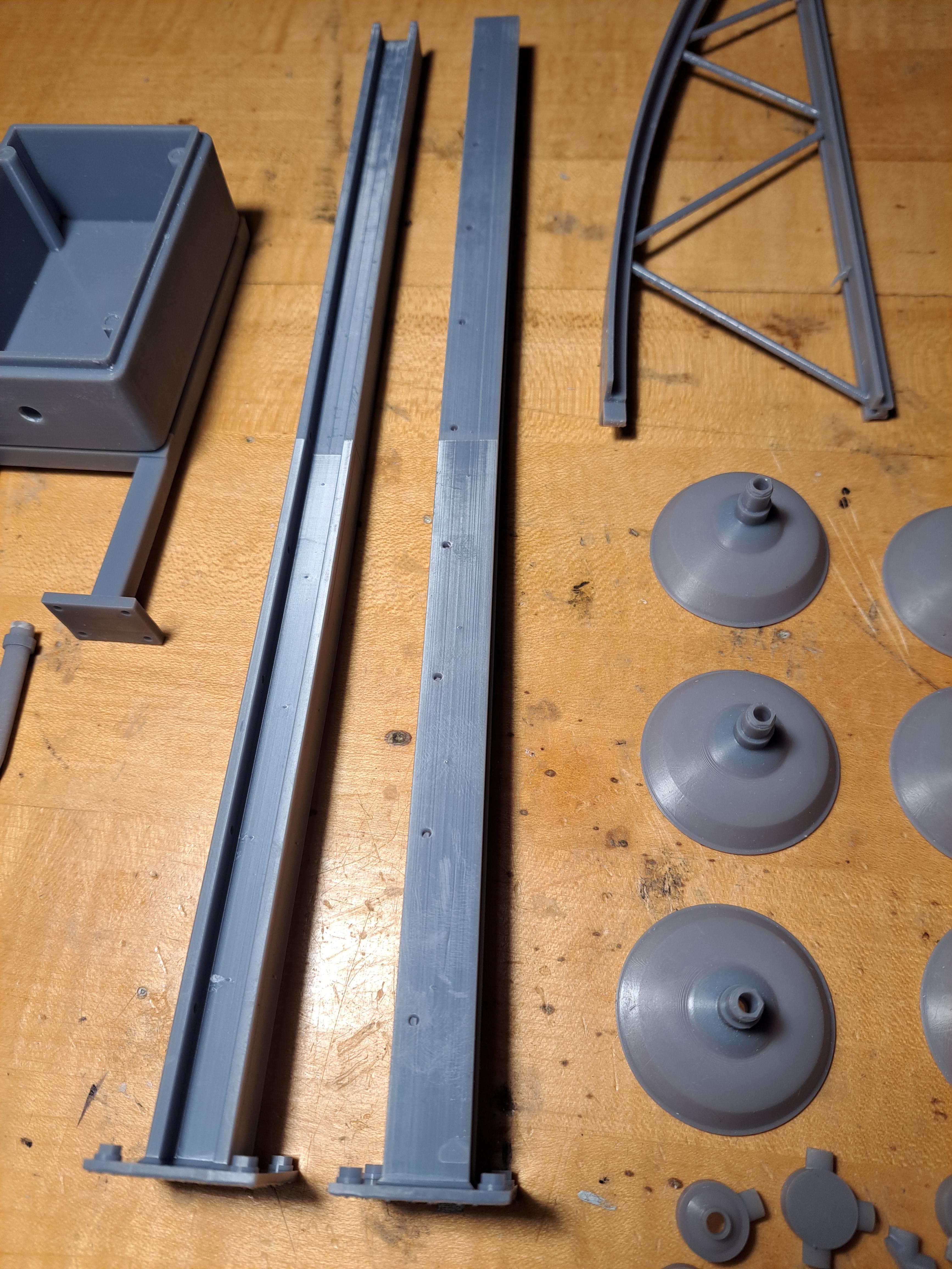
Hello everyone, I'm still here and available to 3d model and print parts of any kind for you. Whether you're into cars, boats, planes... or maybe you need a miniature lathe, mailing machine, drill press or work bench for you custom display setup. If you can think it, chances are I can model it and print it. Here are a few exemples of different things that can be printed. Structural componants such as roof trusses, columns and beams... Electrical componacompsush as light fixtures, electrical boxes, control panel... Plumping componants such as valves, elbows, reducers, tees... I even printed some wicker chairs Don't hesitate to contact me, I'll be happy to help you get that spécial part you just can't find.
-
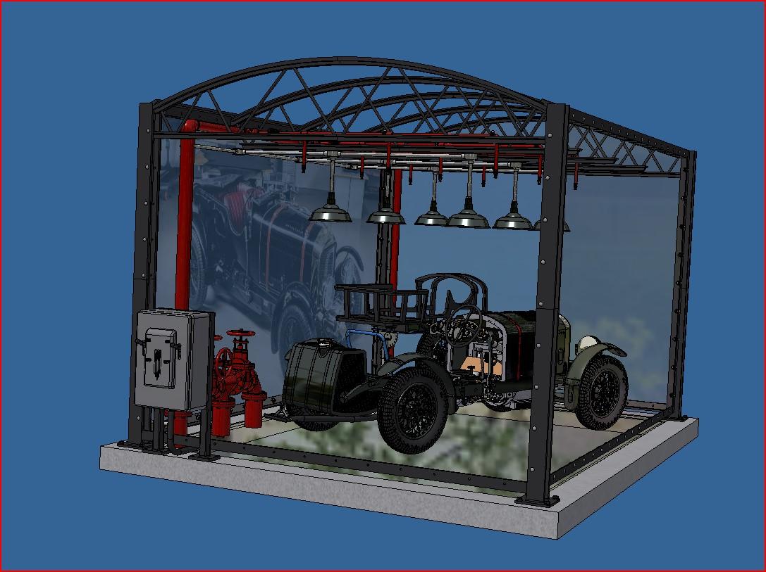
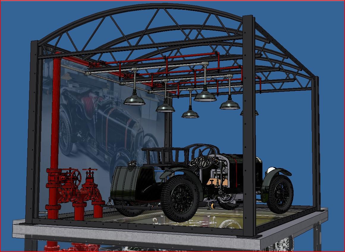
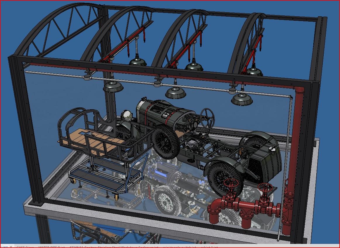
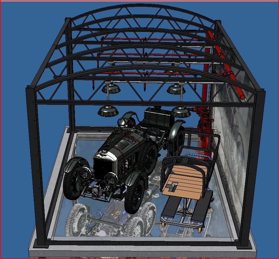
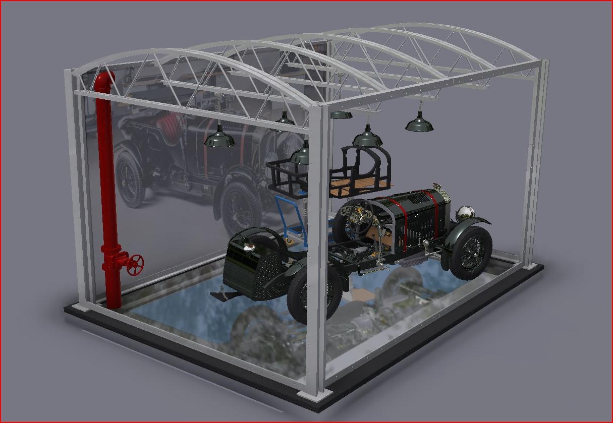
The display case structure is glued up. I should be ready to paint it shortly. I temporarily installed the pipes and lights and placed the car in to see what it will look like. I have to say that I'm very happy with the result. Here's a screen shot of the 3d model And a few pictures of my set up I still need to do some research on how to print the picture of the real car on a plastic film of some sort and to have it translucide.
-
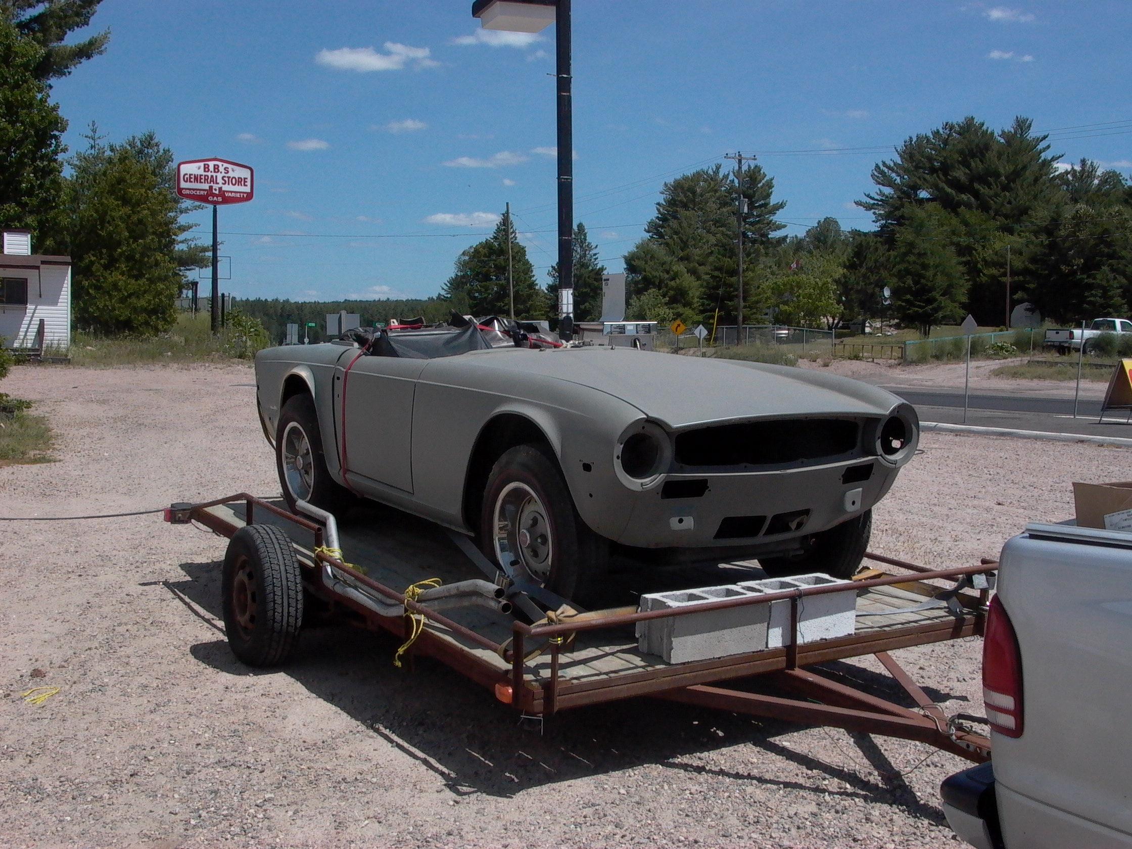
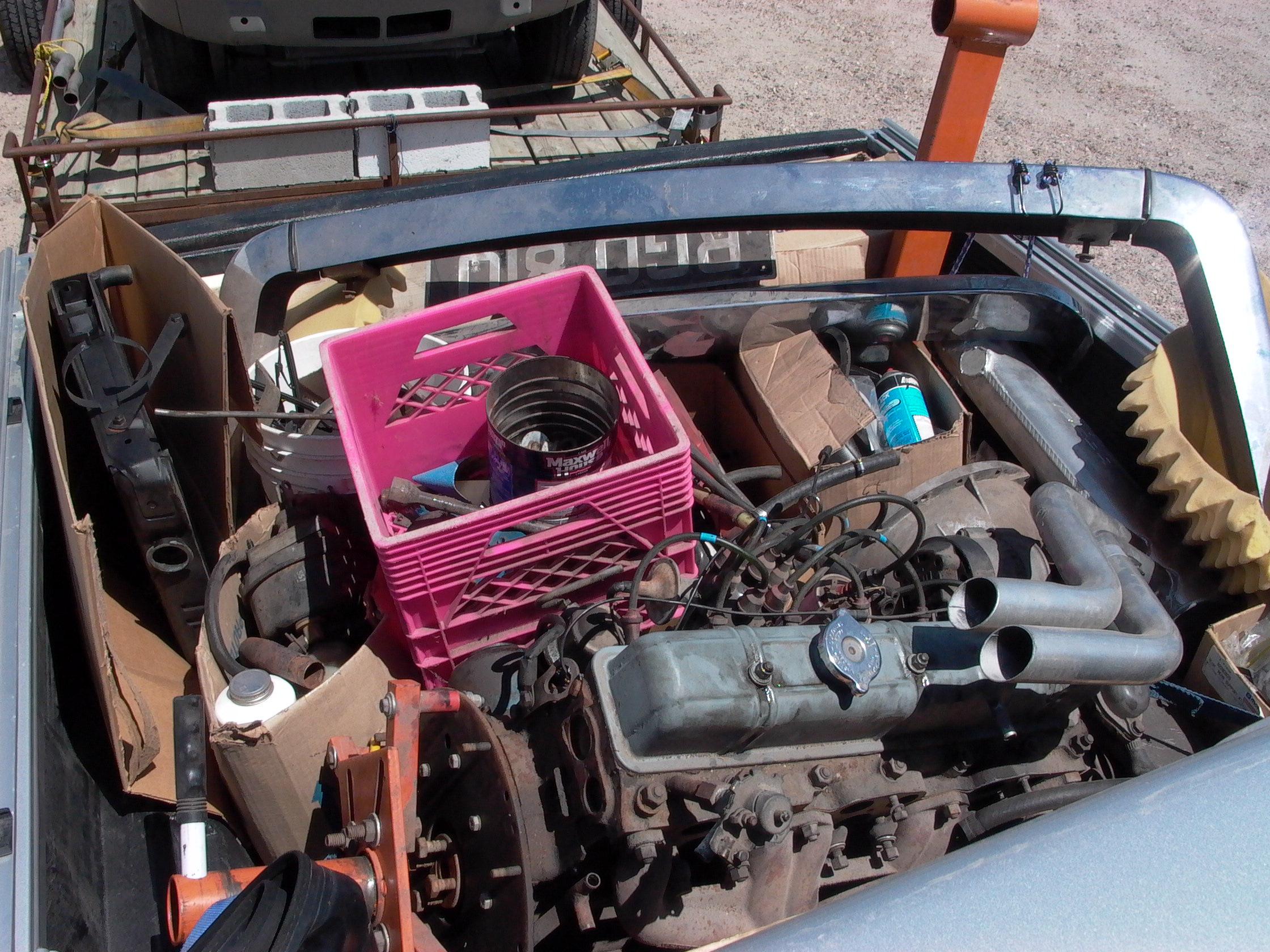
Thank you clipper. The display is almost as fun to do as the car itself... almost... I just put an offer on the old Pocher rolls. I offered 100$ for basically a pile of junk but like I said before, l see this as a restoration project that could be very interesting. I brought an old klunker back to life before and the result is very satisfying. From this in july 2005 To this in july 2007
-
Yep, the switchs work!
-
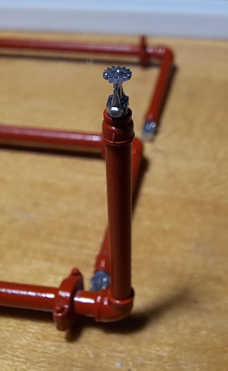
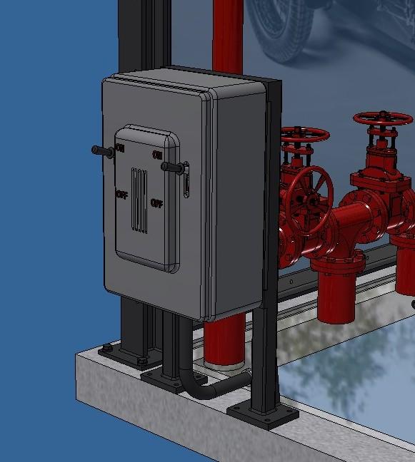
Yes, it is a nice barn find but after some research, it would seem that this model is quite commun for Pocher so not worth much. Still, it would be fun to rebuild it with running engine, lights and much more. Now, back to my current display case project. I started painting the different components and fabricated the front and back panel frames. I received 1mm thick plexiglass. I need a thin plexiglass for the curved roof, I'll see how this thickness works for the side panels. I also assembled the electrical box with the 2 switchs. Here are some shots. Painted sprinkler pipes Sprinkler head Main gate valve painted, l tried to give it a cast look (rugged). I ran out of red paint, wiil get more tomorrow. The lights painted black with white interior. I might try to simulate some dust on it. Also painted the connection boxes. Electrical box painted and assembled Working switchs 20240326_200858.mp4 20240326_200805.mp4
-
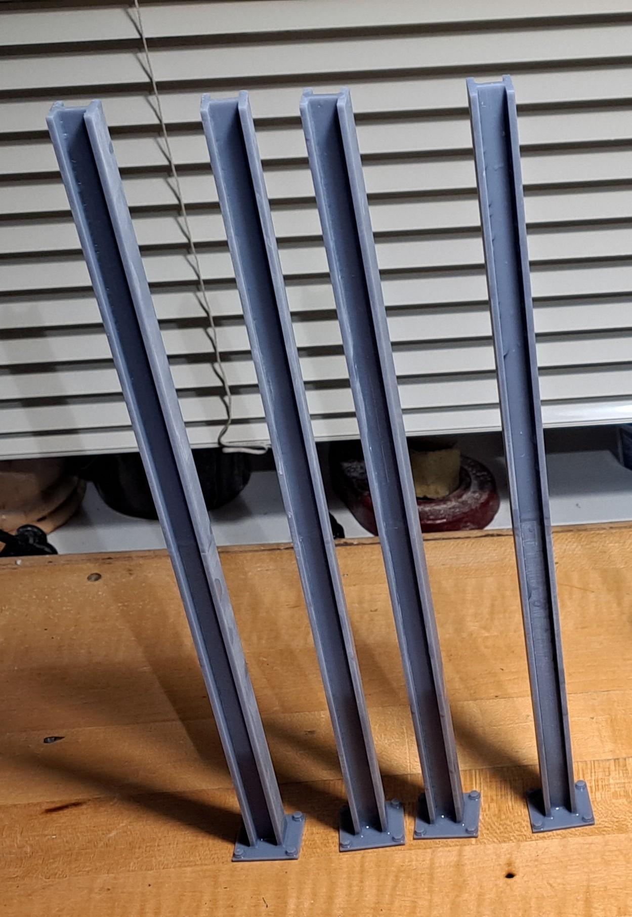
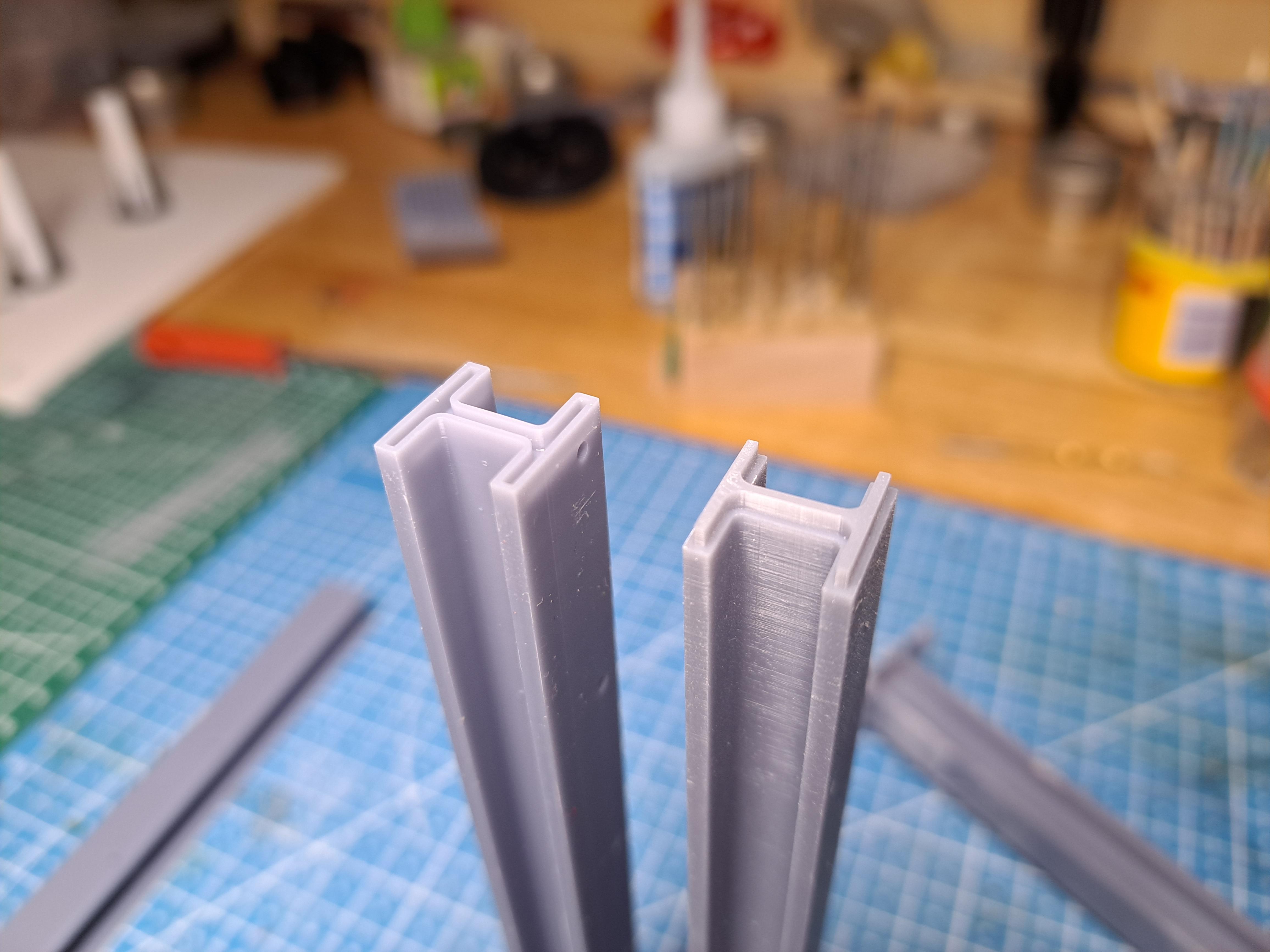
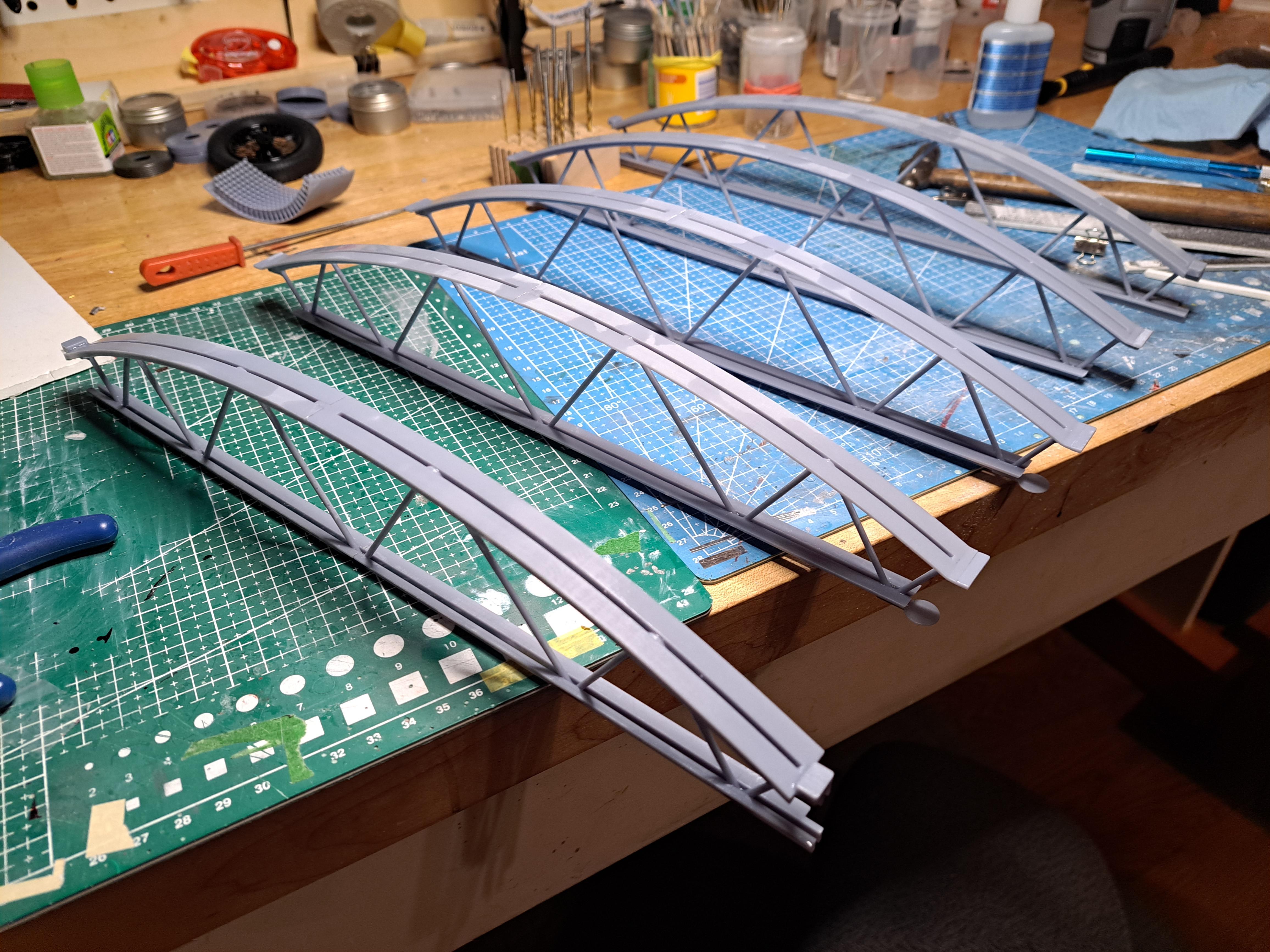
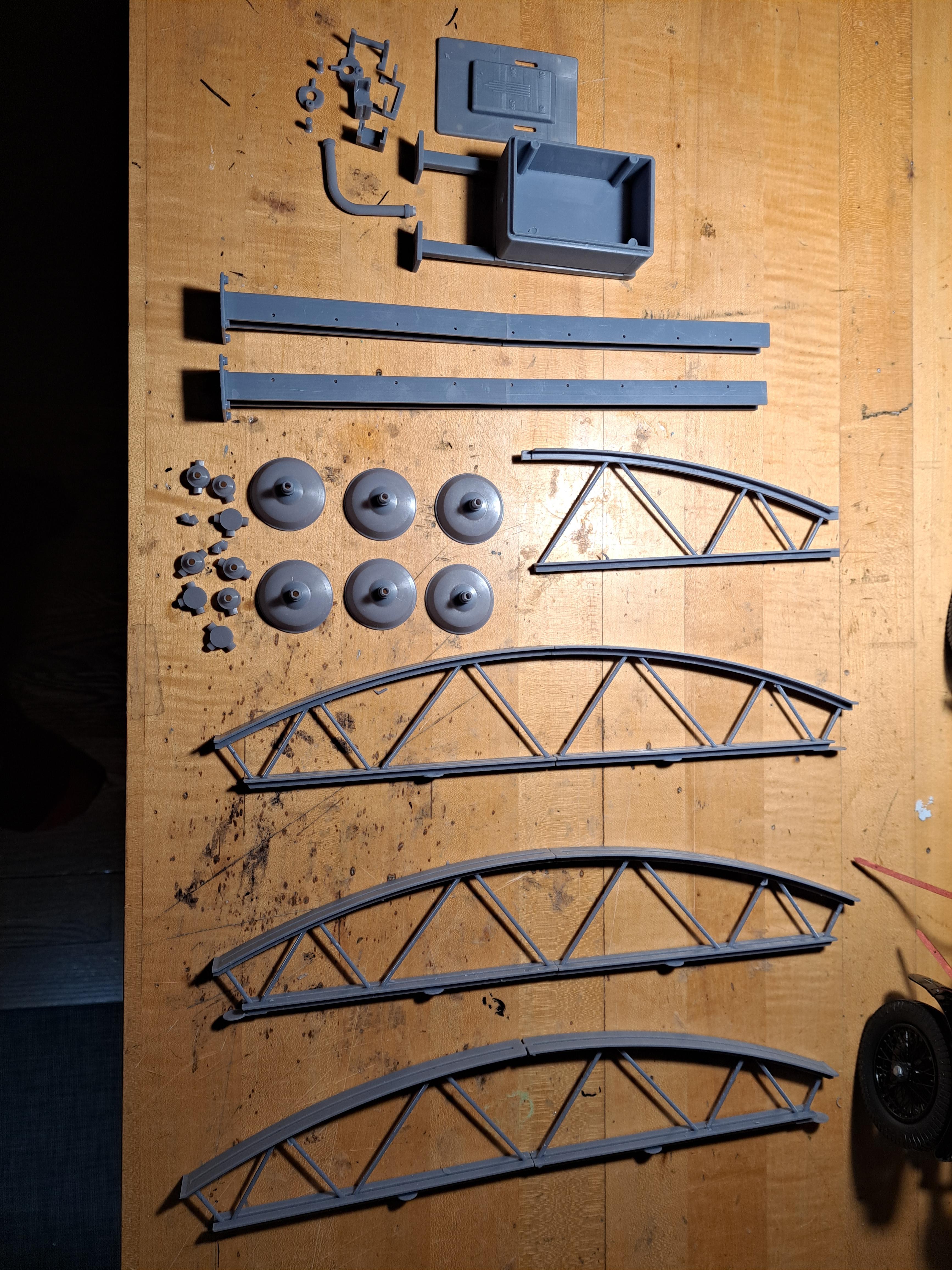
Started some sub assemblies on the display case today. All 5 trusses are glued 4 H columns They were too long to print in one piece so I did them in 2. I added a locating feature at the ends of both half to assure a good alignment. Did the large gate valve assy And the 3 sprinkler pipes This is the only gate valve from my father's inventory that I could fit, there's a small part of him in this. On an other topic, I found this really old and beat up Pocher rolls royce at my local hobby shop. It's missing many parts. I'm thinking it could be an interesting project, total dismantle, refurbishing, and adding some of my special festures to it. But I would need to get for next to nothing... to be continued...
-
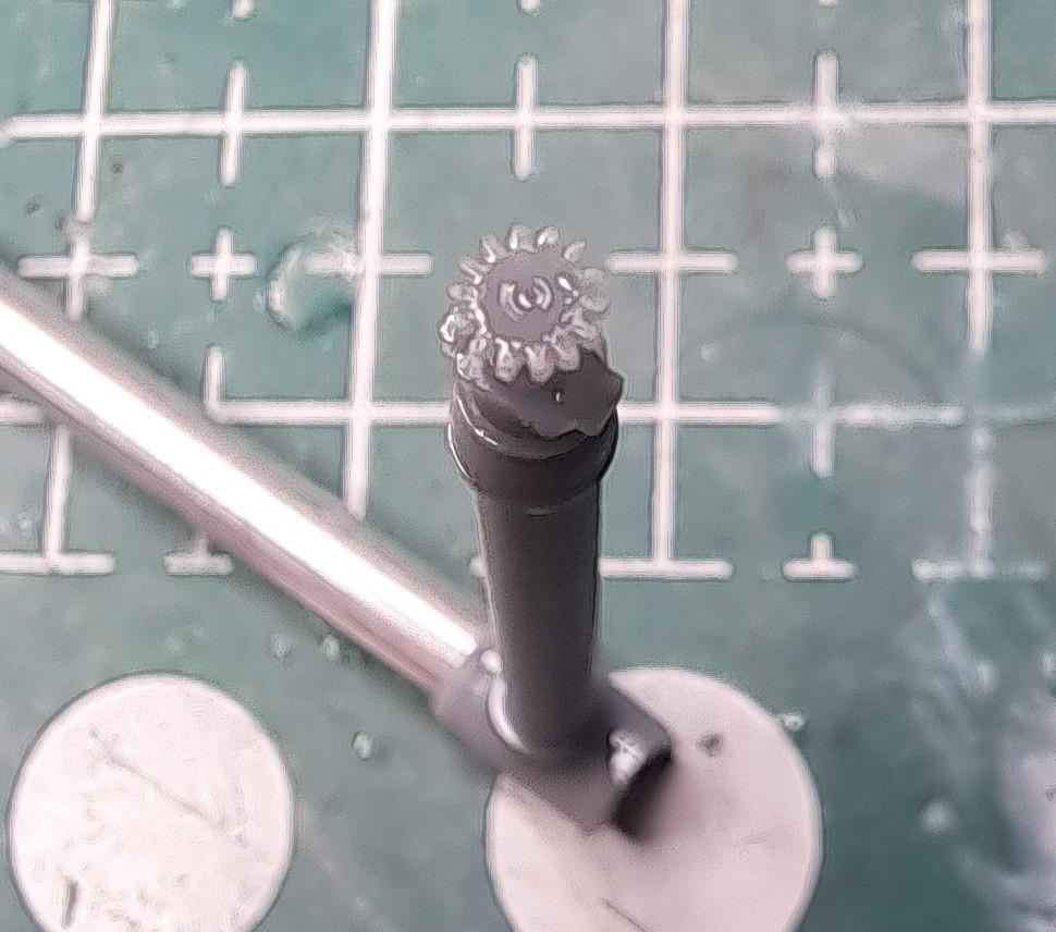
Printed some more parts for the display case. Printing these parts proves to be more complicated then I originaly thought, but I think the final result should be worth it. A bunch of parts Sprinkler head
-
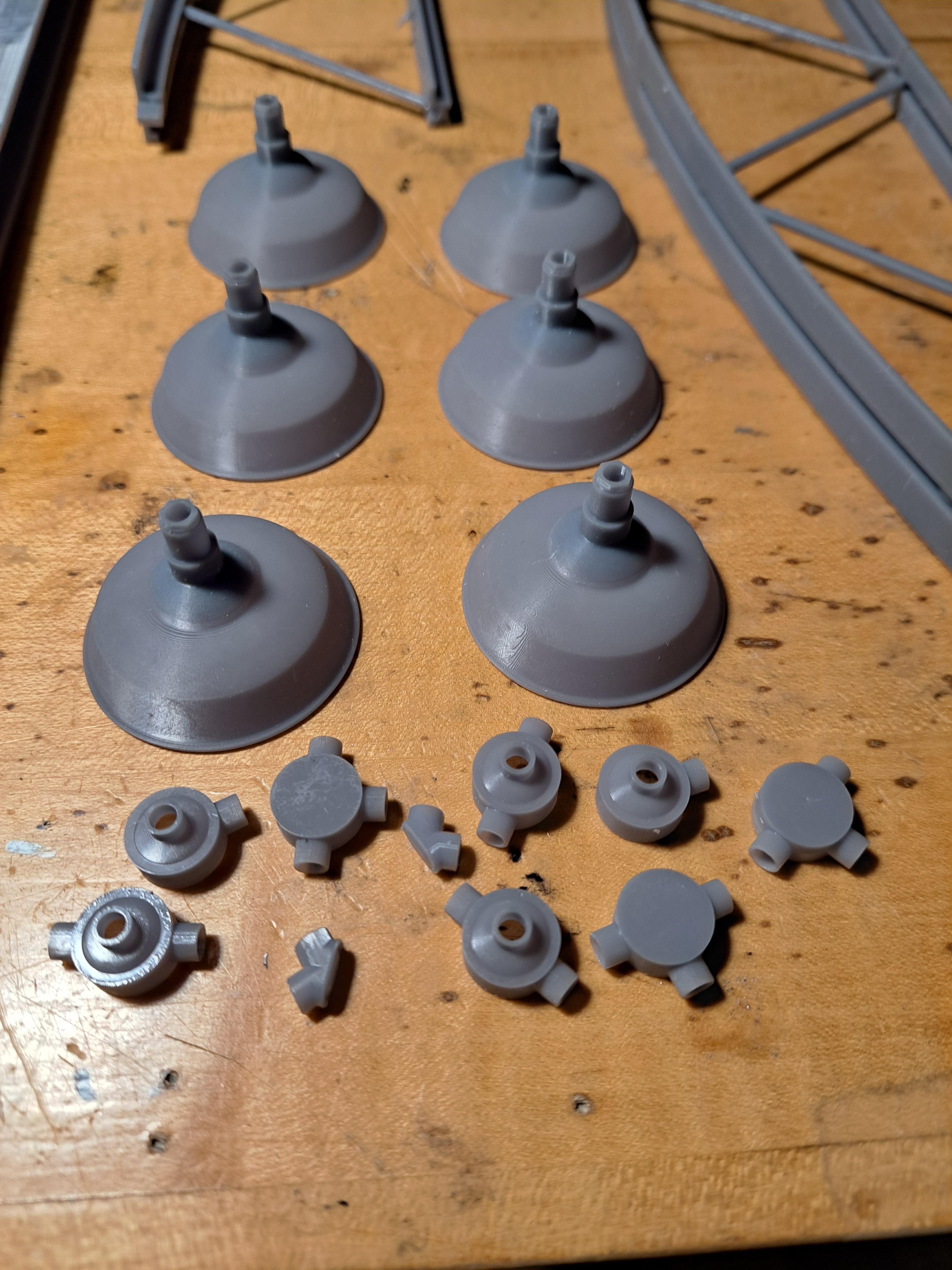
I printed many parts for the display case today. Many more still to print. Structure printing plate Lighting and electrical box printing plate All parts washed and cured Lighting components Electrical box components Structure components
-
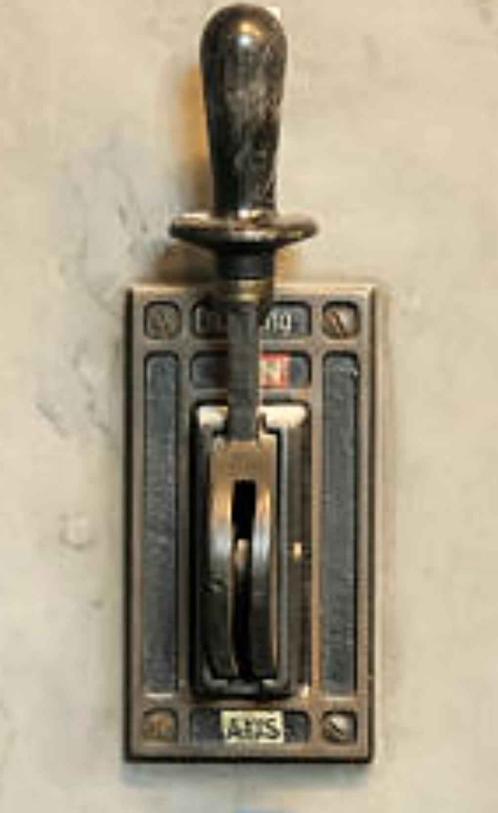
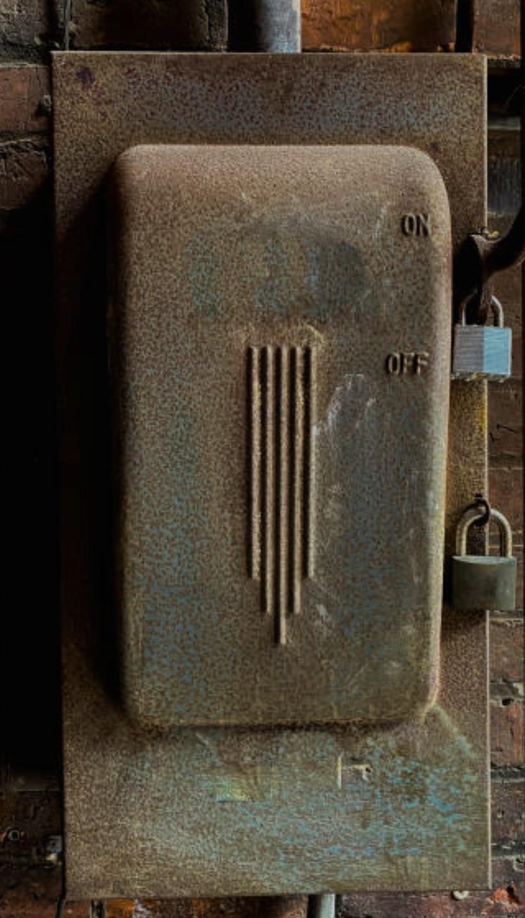
I worked on the display's electrical box. This box will house the batteries and switchs to activate the car's head lights and engine. I wanted to give the box à vintage look and at the same time incorporate 2 levers. I opted for an old disconnect box but normaly, these type of boxes have only 1 lever, I had to adapt a bit. The complete electrical box assembly will be permanently fixed on the outside of the base. It will be possible to remove the display case from the base whitout removing the electrical box. This was my inspiration for the box And for the lever Here's the 3d model I incorporate 2 slider switchs inside that will be actuated by the lever. Since I'm not too sure of the quality of these switchs, l designed a snap in switch holder so that if they fail, I can easily replace them. Naturally, the lid is remocable and held in place with magnets. Some of the parts printed. The lid and support frame ate not correct and will be reprinted. 20240320_210323.mp4
-
More done on the case today, water piping and lighting finished. I'm still playing around with the frame color but I think flat black would be best.
-
I'm only at the design stage, nothing fabricated yet. It will be a mix of printed parts, Plastruct and Evergreen extrusions (my hobby shop has a full range of both product) and Britannia parts for some of the smaller water valves, the bigger valves will be printed.
-
A bit more done on the display case, slow evolution.


.jpg.4a61aa236935b41eed1a0e08249bbff9.jpg)