kenlwest
-
Posts
277 -
Joined
-
Last visited
Content Type
Profiles
Forums
Events
Gallery
Everything posted by kenlwest
-
I felt like I was performing eye surgery on a house fly as I was removing the chain from the print supports! The brake drums fit through the large sprocket, then the wheel bolts to the brake drums. After everything is fit to the chassis, I will explain how the mechanical speed control, and differentials work.

-
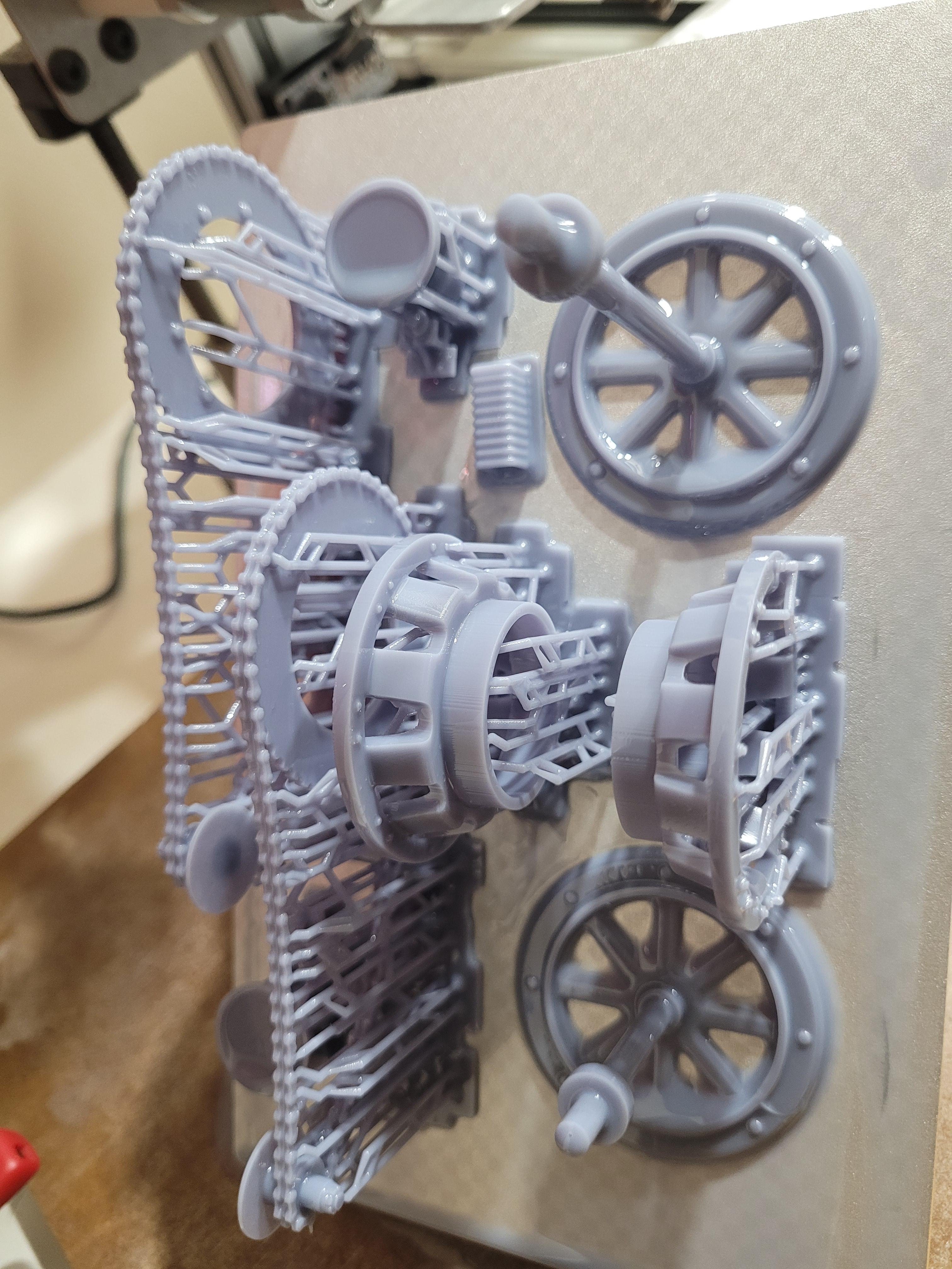
Just pulled from the printer. Happy that the chains came out nice.
-
Ready to print the brake drums, drive chains, differential parts, and drive wheel.
-
Looking at the pictures, it is definitely not the ws frame. IF the body is not twisted (common on many open top bodies), then it's the roof. I would take a good look at the body first.
-
I lied... one more! I wanted to see how the well the spring wires are supporting the weight. Seems to work great, and at this scale, they are hard to see.
-
Last picture for a Friday night... the wheels placed on axles to illustrate the size of the model. Added a quarter for reference.
-
Axles attached to the springs. Note the small wires used to support the weight of the model. My hope is that they won't be too visible.
-
All four springs in place on the frame, shown upside down.
-
The rear springs in place as well as the frame-mounted spring stops.
-
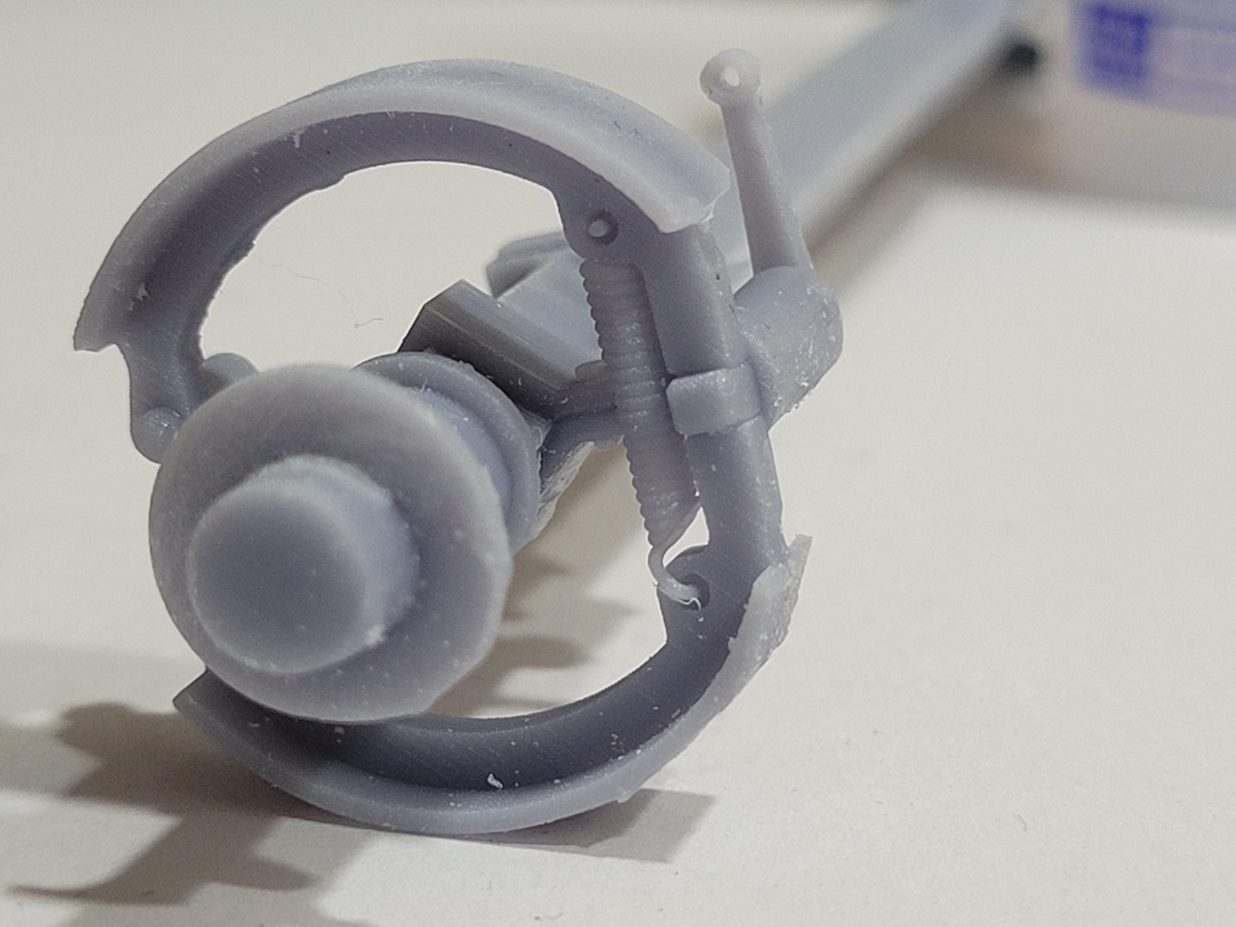
Might be a little hard to see, but here is a picture of the brake system. The vertical lever is pulled by a steel cable (by pressing the center pedal). As the lever is pulled, it turns a metal cam between the upper and lower brake shoes. The turning cam spreads the shoes to make contact with the drum assembly. The vertical spring pulls the shoes together and away from the drum when the pedal is not pressed. I was able to recreate this from parts shown in the service parts manual, and photos on the internet.
-
The front suspension is printed in one piece. Temporarily tacked to the front wheels.
-
I printed the wheels using 2 different types of printing (filament vs resin) as a comparison. The dark wheel is resin, and light gray is filament. Both methods have their pros and cons. Obviously, resin is the better method for the wheels.
-
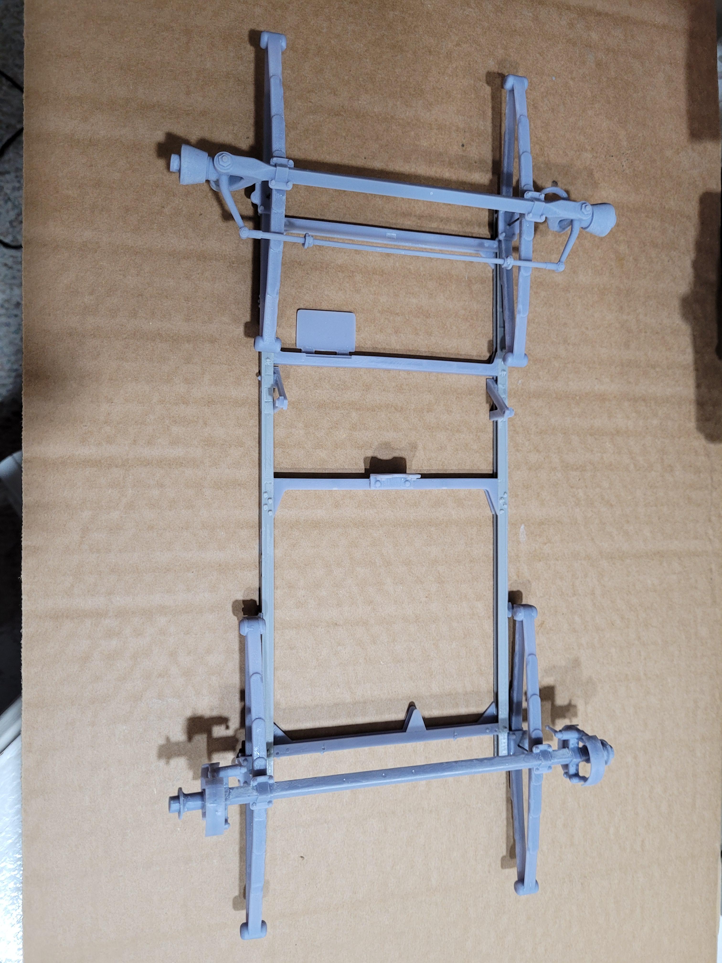
I have been into 3d printing for a few years now, and the technology, cost, and accuracy just gets better and better over time. It will be awhile before 3d printing could compete with injection molded plastic kits. For now, 3d printing is really great for hobbyists wanting to design and build low volume, not available subjects. Here is a shot of the frame with engine mounts and fasteners added. The leaf springs are nice and detailed, however, they are not very stiff, and will need to be reinforced. I have a plan for addressing that later on.
-
A quick preview: the seat and body sitting on the frame. At 1:8 scale, the width of the body and frame measure 4.5 inches.
-
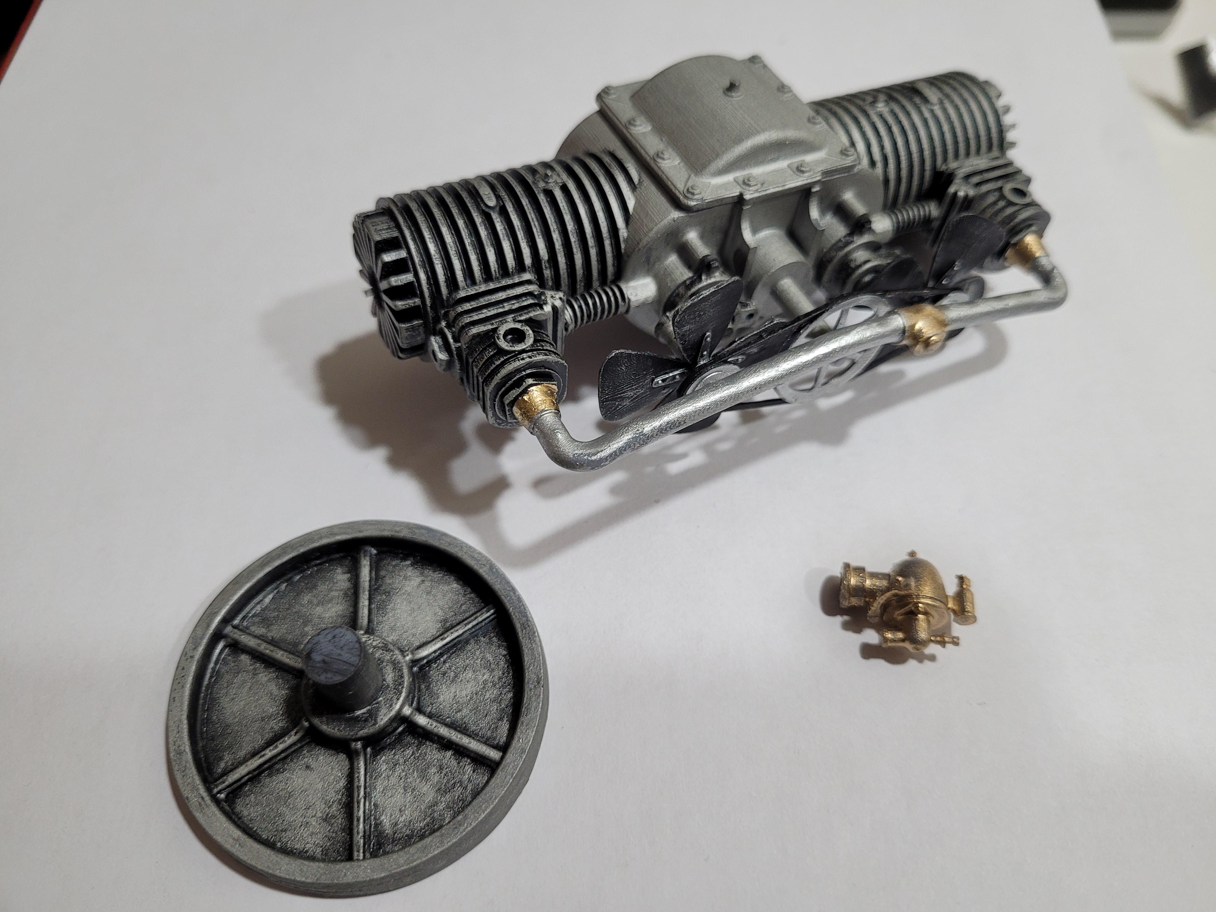
I added the cooling fans, pulleys and cam boxes. Here is a picture of the progress, carb and flywheel.
-
Not familiar with it. Is it a brand name?
-
That would work, but I don't really have the tools or skills for that. I have seen some really great work with brass on this forum though!
-
Engine assembly so far: the resin parts tend to be heavy, so I need to find a way to make the suspension parts strong enough to support the weight. Normally this would not be a problem on modern cars, but these cars are very fragile in small scale.
-
Main engine assembly: I used a spring from an ink pen to represent the valve return springs. Also, a picture of the real engine. The 2 cylinders are not offset to accommodate individual crank journals. However, the connecting rods are offset. I have never seen this on any other engine.
-
The rest of the engine parts: Front engine cover and valve boxes, flywheel shield, spark plugs and fill cups, fan drive belt and pulleys, cooling fans, and cam boxes.
-
The first set of engine parts. Starting at the top, the 2 crankcase halves (cylinders were casted with the case), flywheel, friction plate, case cover, intake pipe, carburetor, and starter engagement cog.
-
Yes, CAD and 3d printed.
-
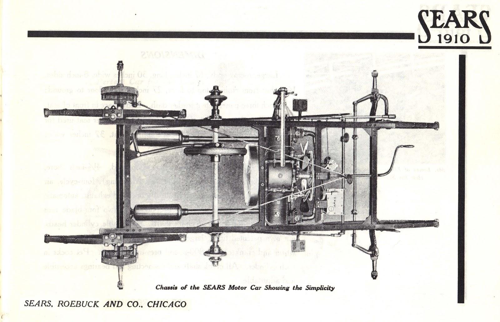
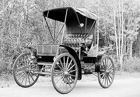
Starting with Frame... there were several variants of the Sears MB, and the length of the frames were modified accordingly. Here is a picture of a completed chassis for reference.
-
To all, Early Automobile subjects are not very common in this forum. Having worked in Automotive Design for over 35 years, I have always been intrigued with the innovation and development that these early subjects brought to the market. The Sears Motor Buggy has an interesting story that I hope to tell through this thread. The Sears Motor Buggy was produced from 1908 through 1912. The predecessor to the Sears Motor Buggy was the Krotz Motor Buggy. Alvaro Krotz was an innovator and entrepreneur who left his mark on several industries including telephones and automotive tire development. When Sears Roebuck decided to get into the auto business, they partnered with Krotz to build the car, and renamed it the Sears Motor Buggy. Here is a link to the Krotz/Sears story. https://www.hemmings.com/stories/article/alvaro-krotz I hope you will find this an interesting build. There is enough information out there to build a reasonably accurate model.
-
Perfect in every way.