.jpg.54ecf0d4a006234146ea24c7f6762038.jpg)
redneckrigger
-
Posts
1,578 -
Joined
-
Last visited
Content Type
Profiles
Forums
Events
Gallery
Everything posted by redneckrigger
-
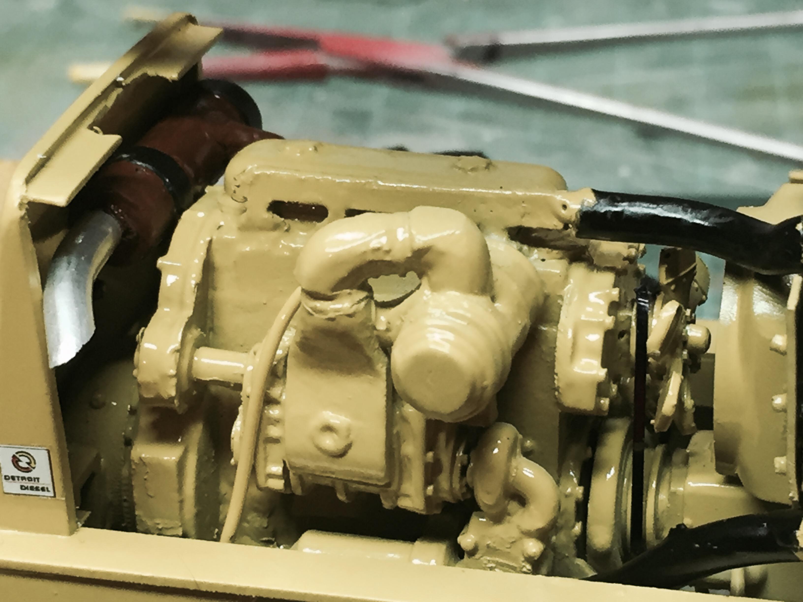
.thumb.jpg.4bca3333e1da4027c381d8d56a564ec1.jpg) For sure! As a former Detroit owner in a couple different rigs, I know that they like to mark their territory! If they aren't dripping, they are dry! Not sure what the next project will be, but it's gonna have to go a beat to beat this one for a challenge!
For sure! As a former Detroit owner in a couple different rigs, I know that they like to mark their territory! If they aren't dripping, they are dry! Not sure what the next project will be, but it's gonna have to go a beat to beat this one for a challenge! -
Yup, a Cat 12 made for me by a friend of mine, John Alan Nelson. But since I have a thing for Galion, if I do one it will be a Galion for sure!
-
Hmmmmm.......look what just appeared on my bench.......! Harbingers of things to come?????

-
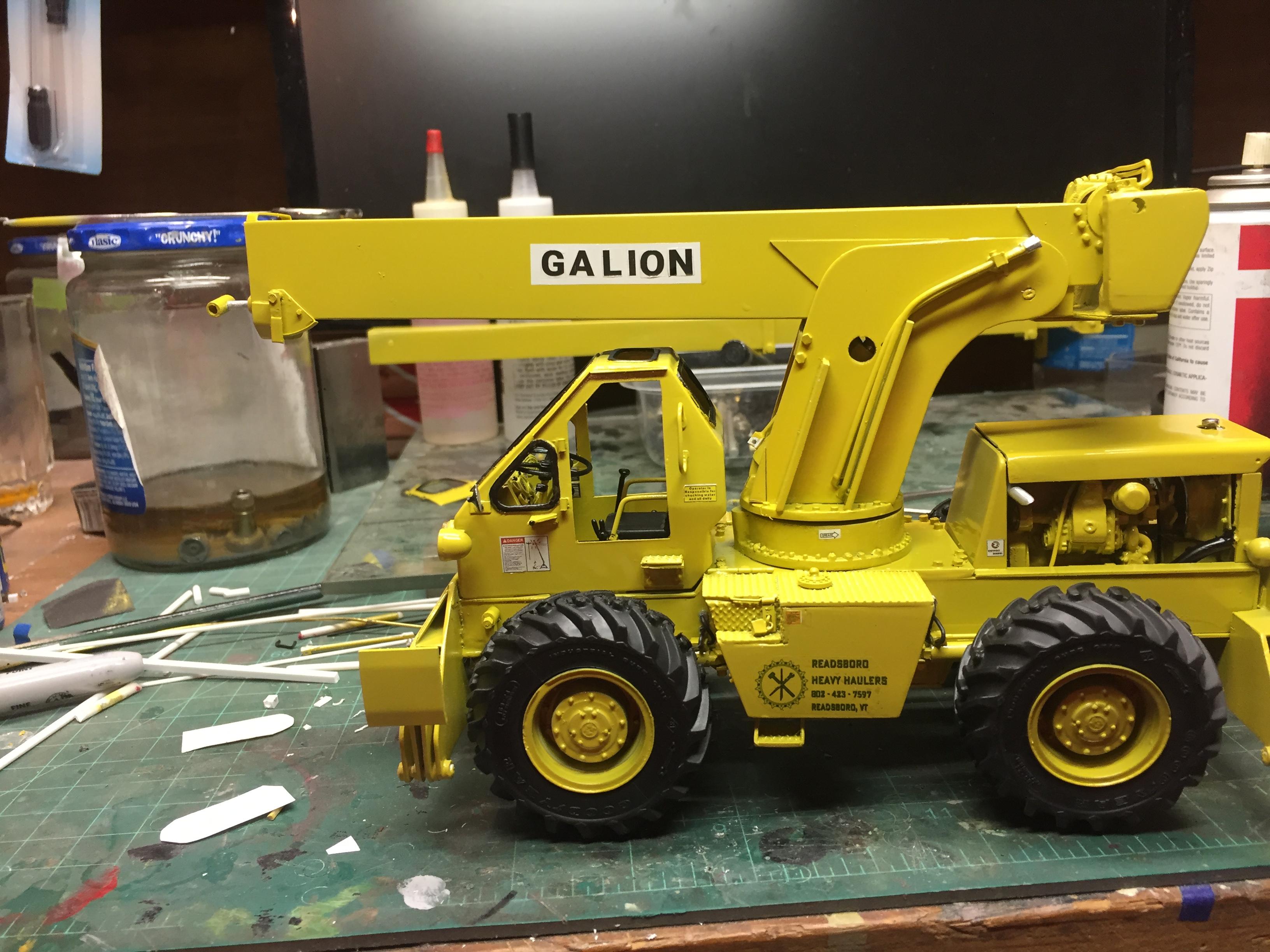
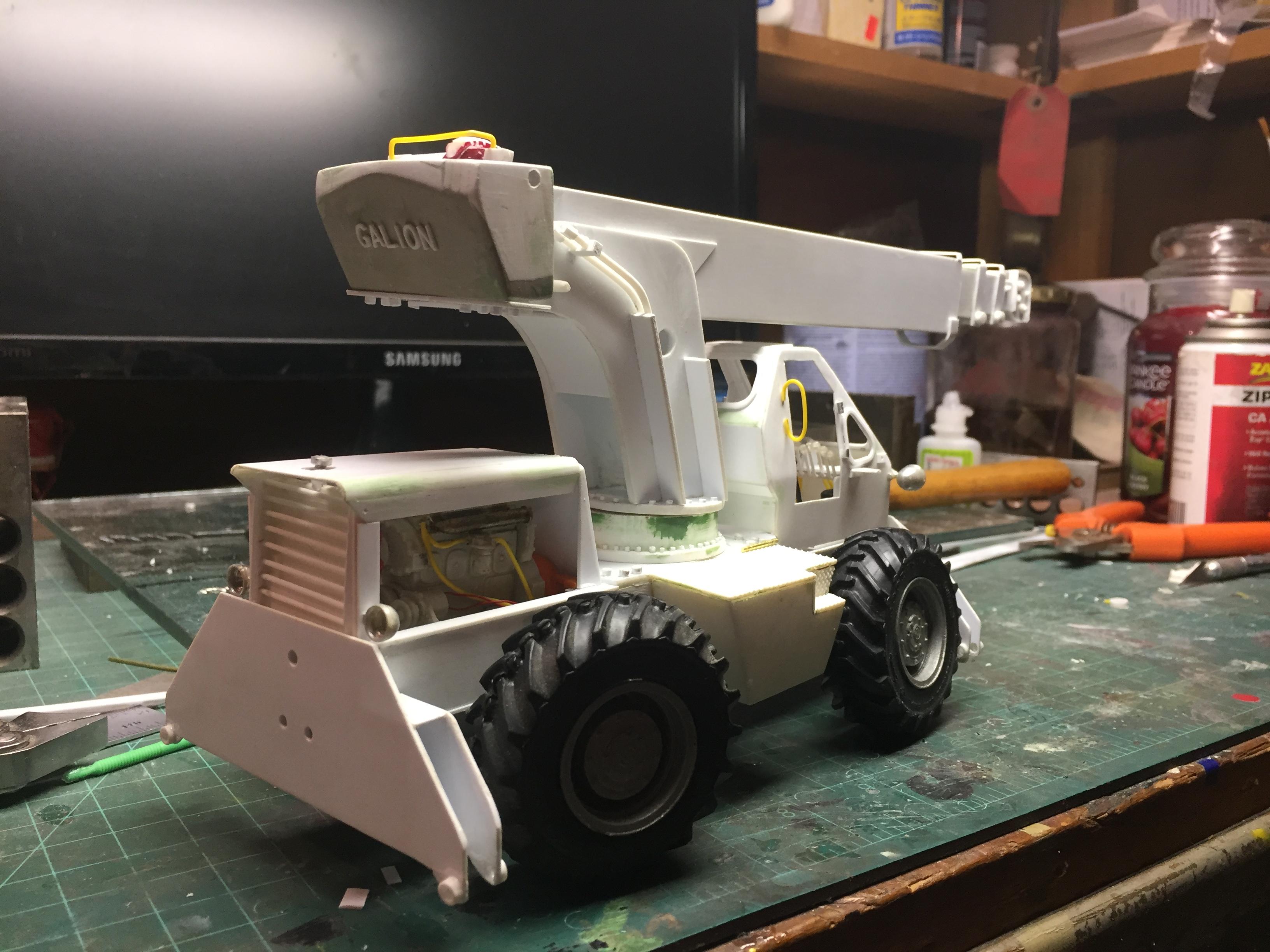
Got the lower chassis all done, exhaust installed, wheels and tires on, mirrors installed, head and tail lights installed, fan belt and fan shroud installed, decals all installed, boom sections assembled, and here is what it looks like so far. Still have glass to cut and install, doors to mount, boom hoses to attach, winch piping and cabling to do. Then some light weathering and she's done!
-
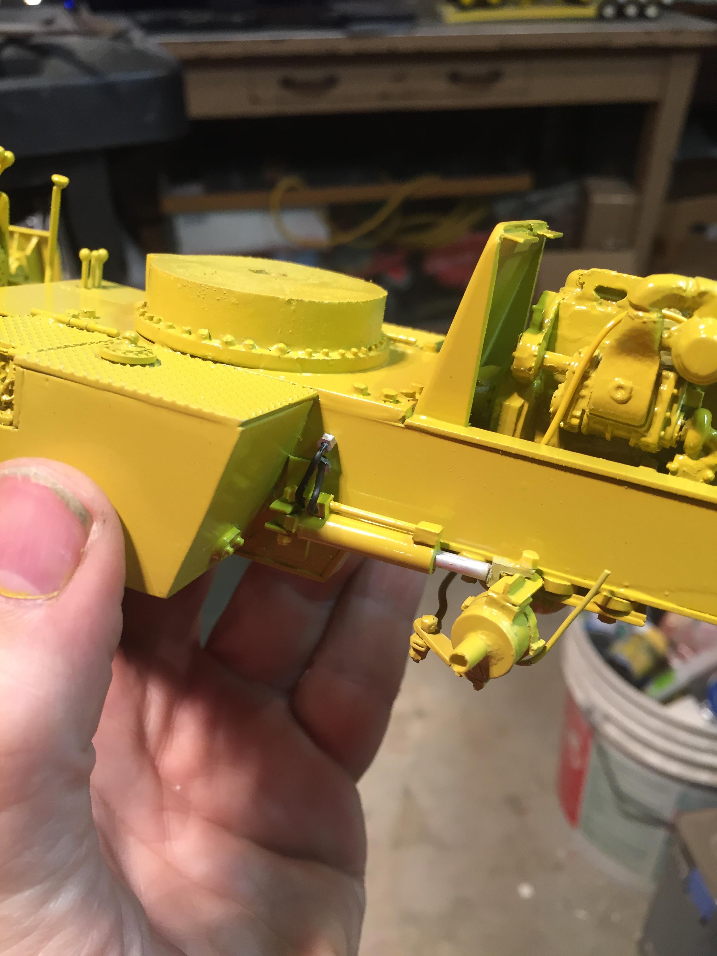
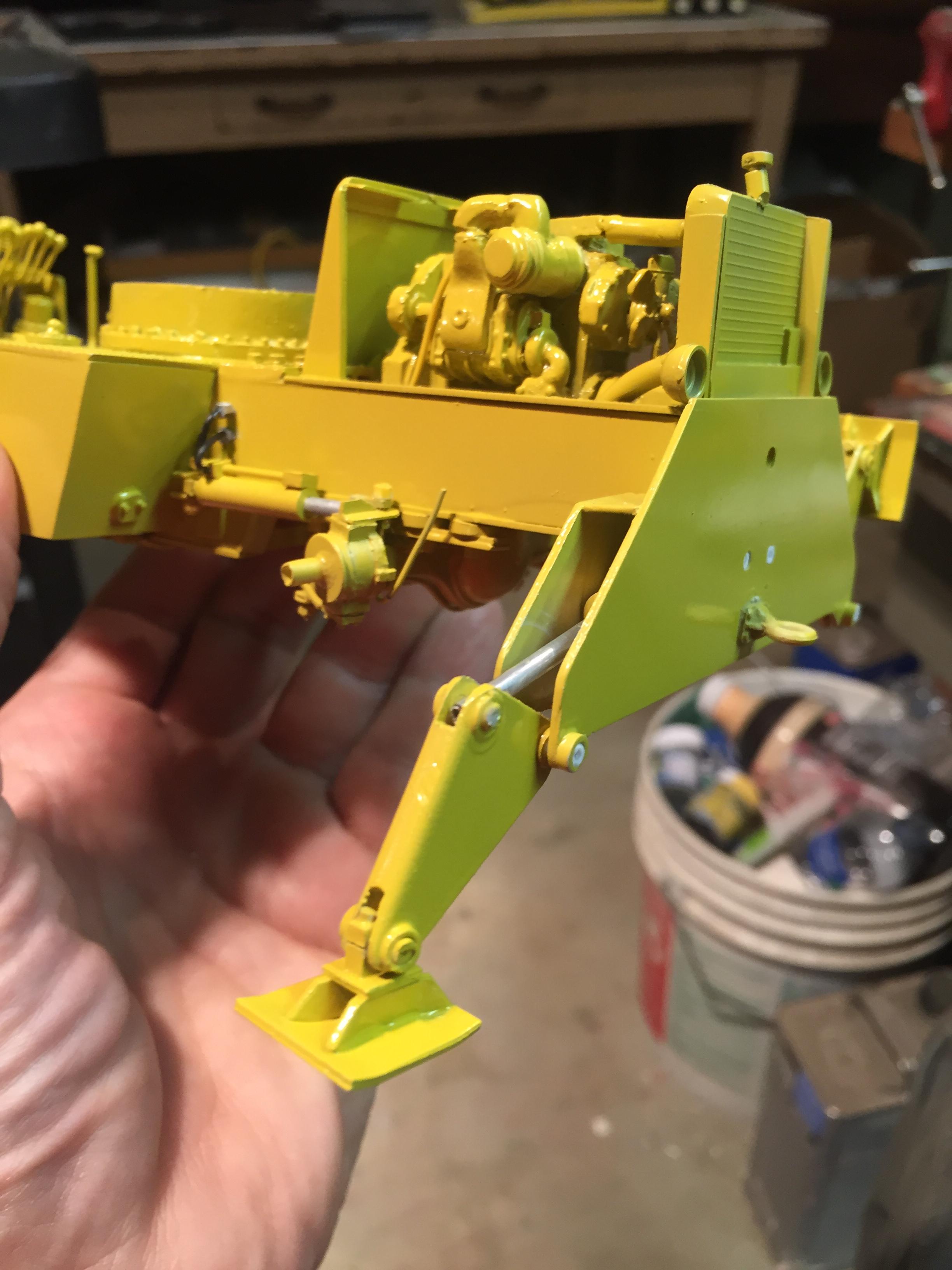
Steering cylinders installed and piped, outriggers installed & piped. Operators controls detailed, gauge decals, caution decals, bits and pieces here and there, and the window gaskets painted.
-
THAT is such a superb build you did, Charlie..............I want to make one up as an M54 wrecker, or as an M52 with a tank on the back, to replicate one we built for our fire department with a 2800 gal tank, square dump discharges, etc. It was a 1961 Mack. Or, to be the 1962 M54 I had at my old shop, which was a Reo as well. So many projects, so little time!
-
I will do that with the M54 Charlie thank you! I have kept a rough total and it is well over 1000. But I think I will try to get an accurate total. Thank you for the good words.........you have been my inspiration as I never once tried a scratch build before that roller. It is fun that cannot be beat! Assembly starts tomorrow night. Needed to exercise patience to let the paint dry so I don't mess it up with fingerprints.......hard learned lessons from times gone by!
-
I would totally appreciate that Jeff! I'll send you a message. Thanks!
-
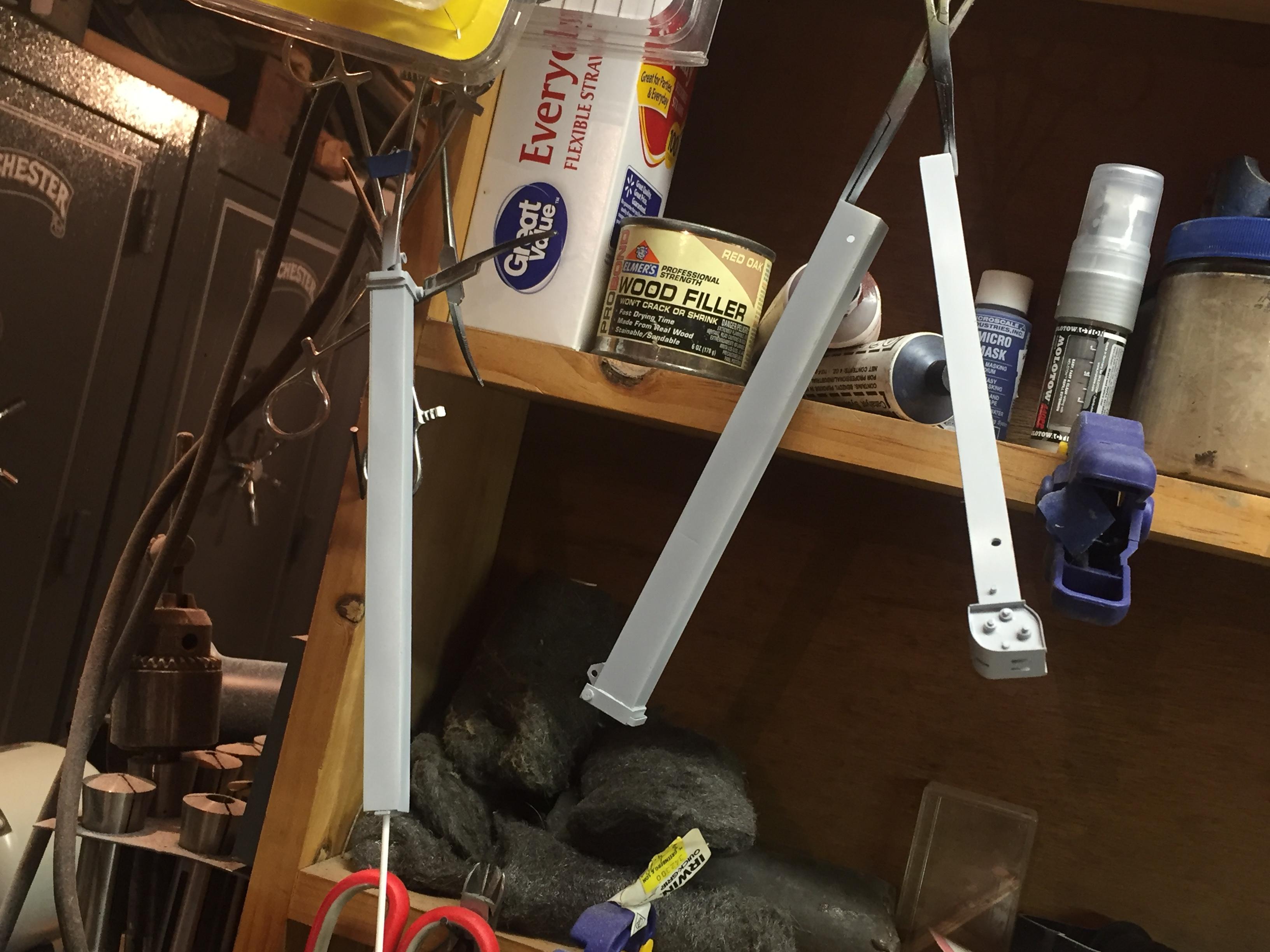
Unmasked and SO tempting to start assembly. But, gotta exercise patience!
-
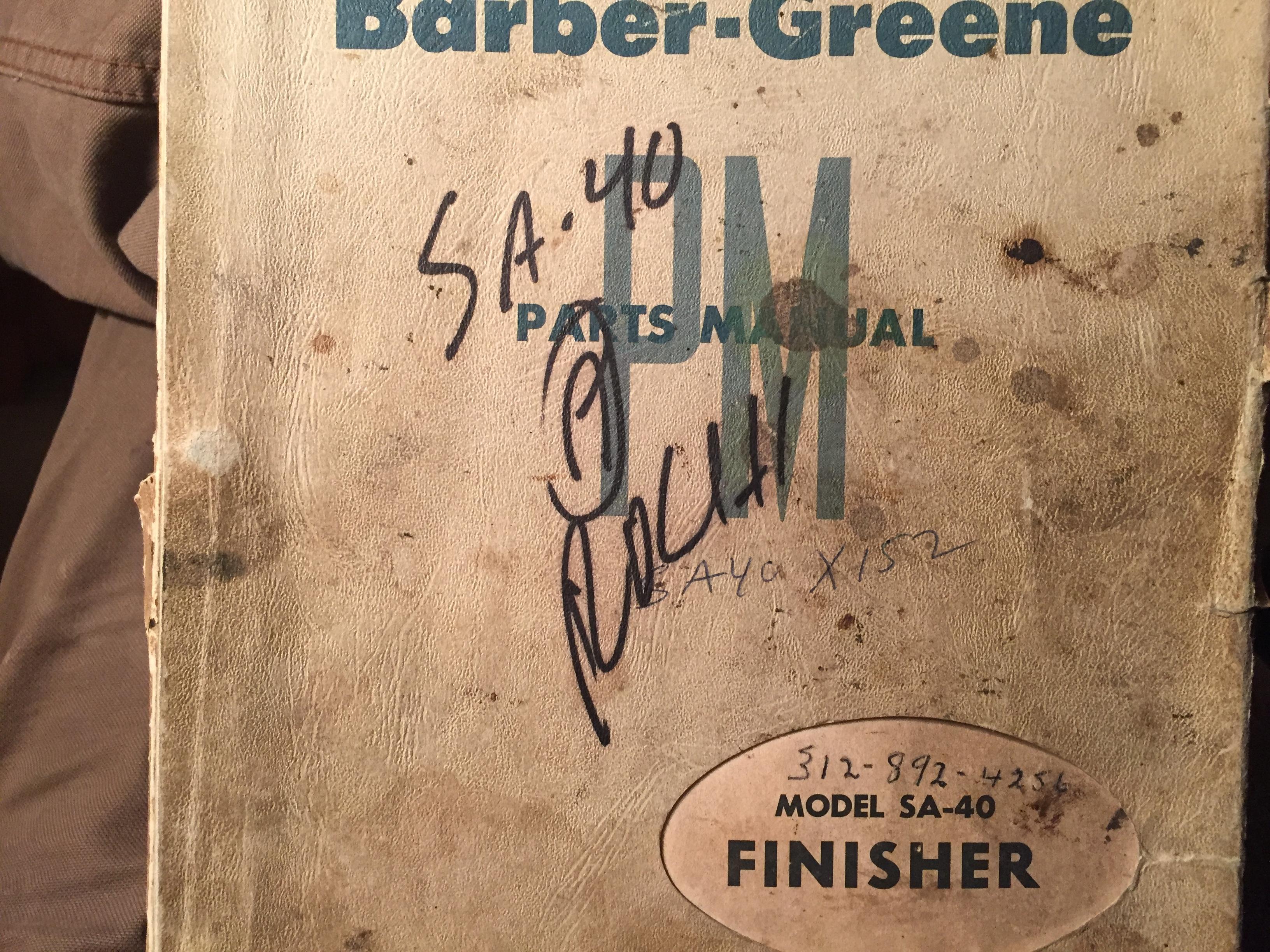
Aw man, Jeff, did ya REALLY have to post that photo???? THAT looks very interesting! Maybe time to hunt down some manuals.............................!
-
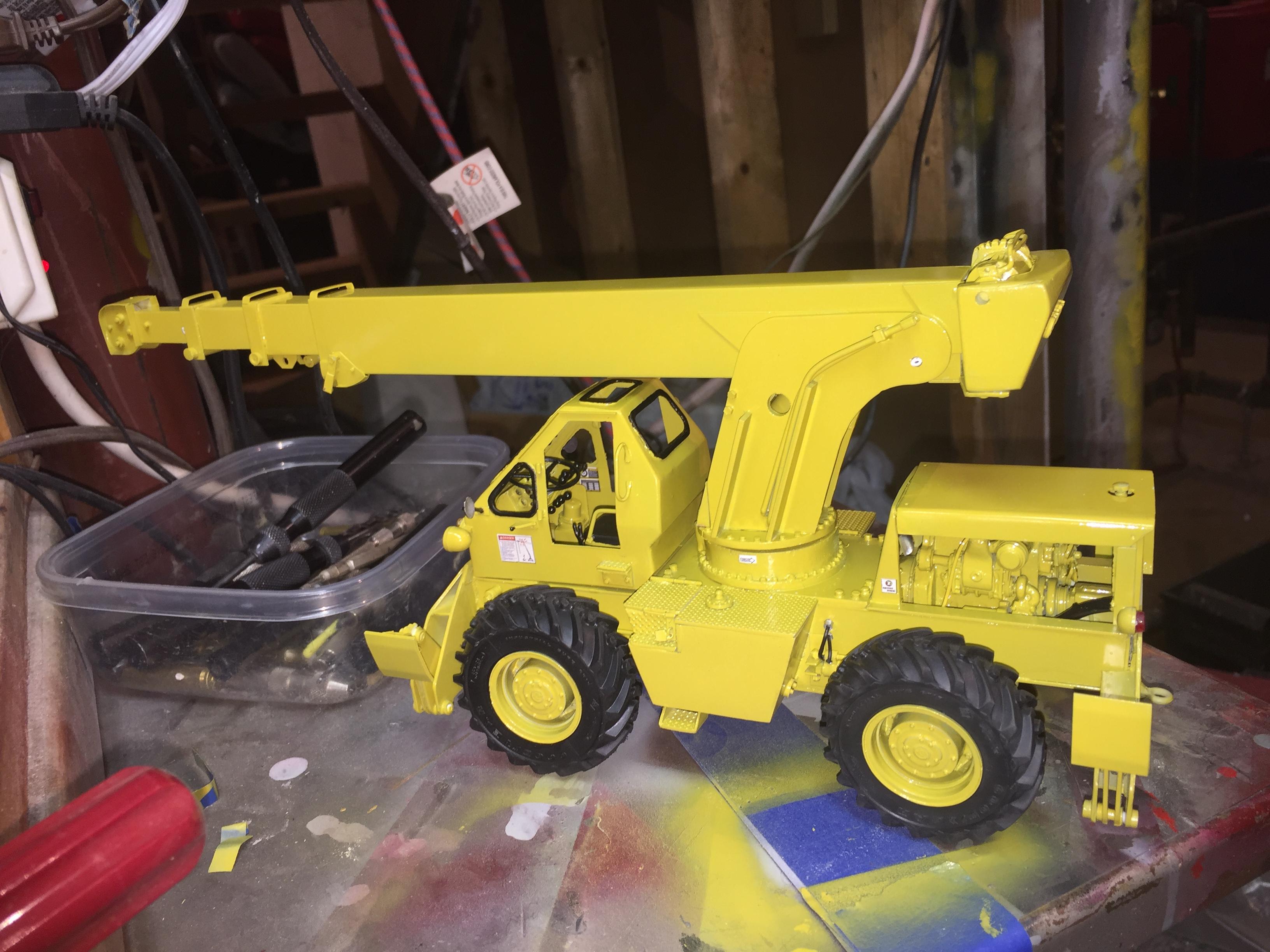
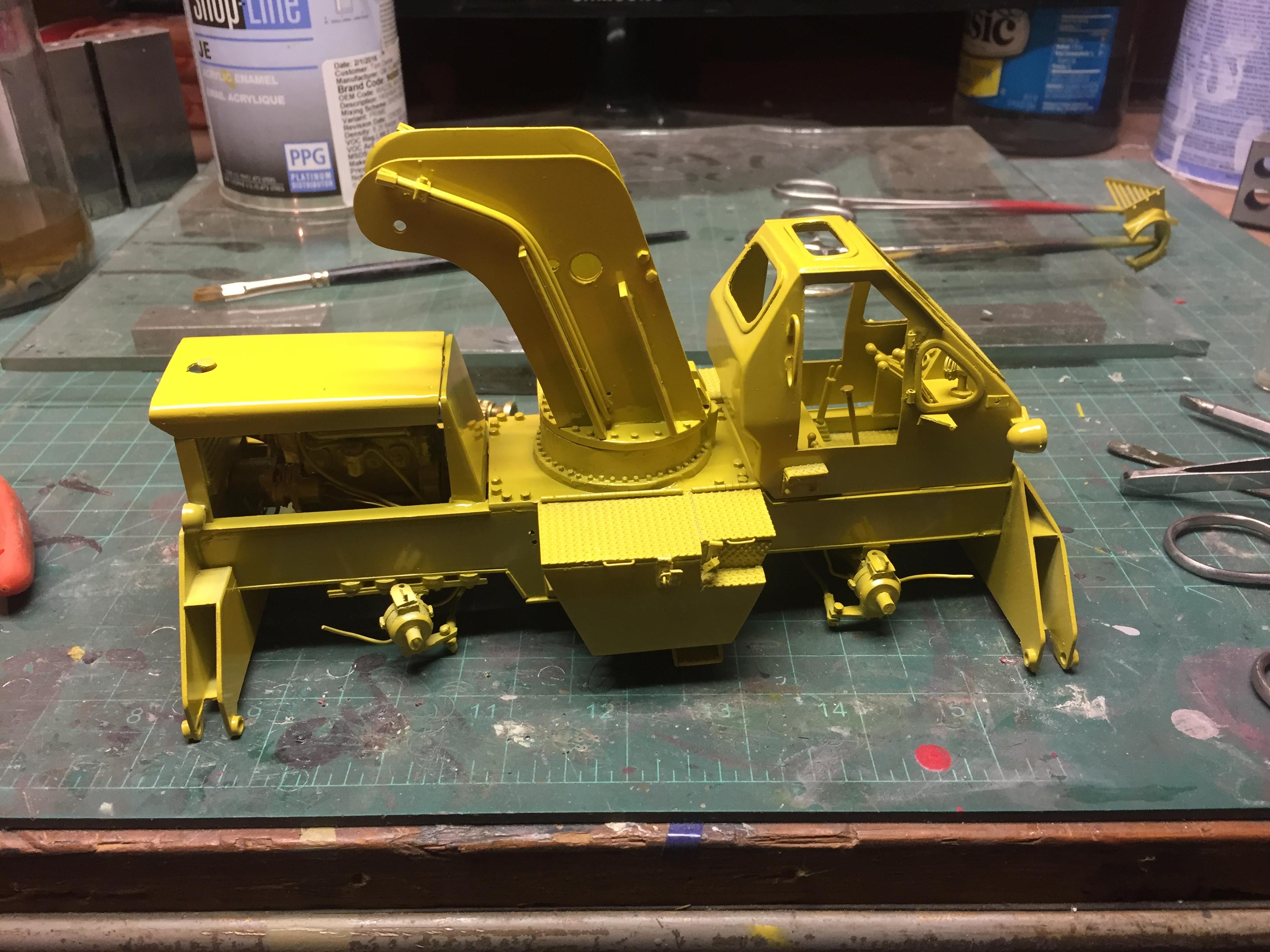
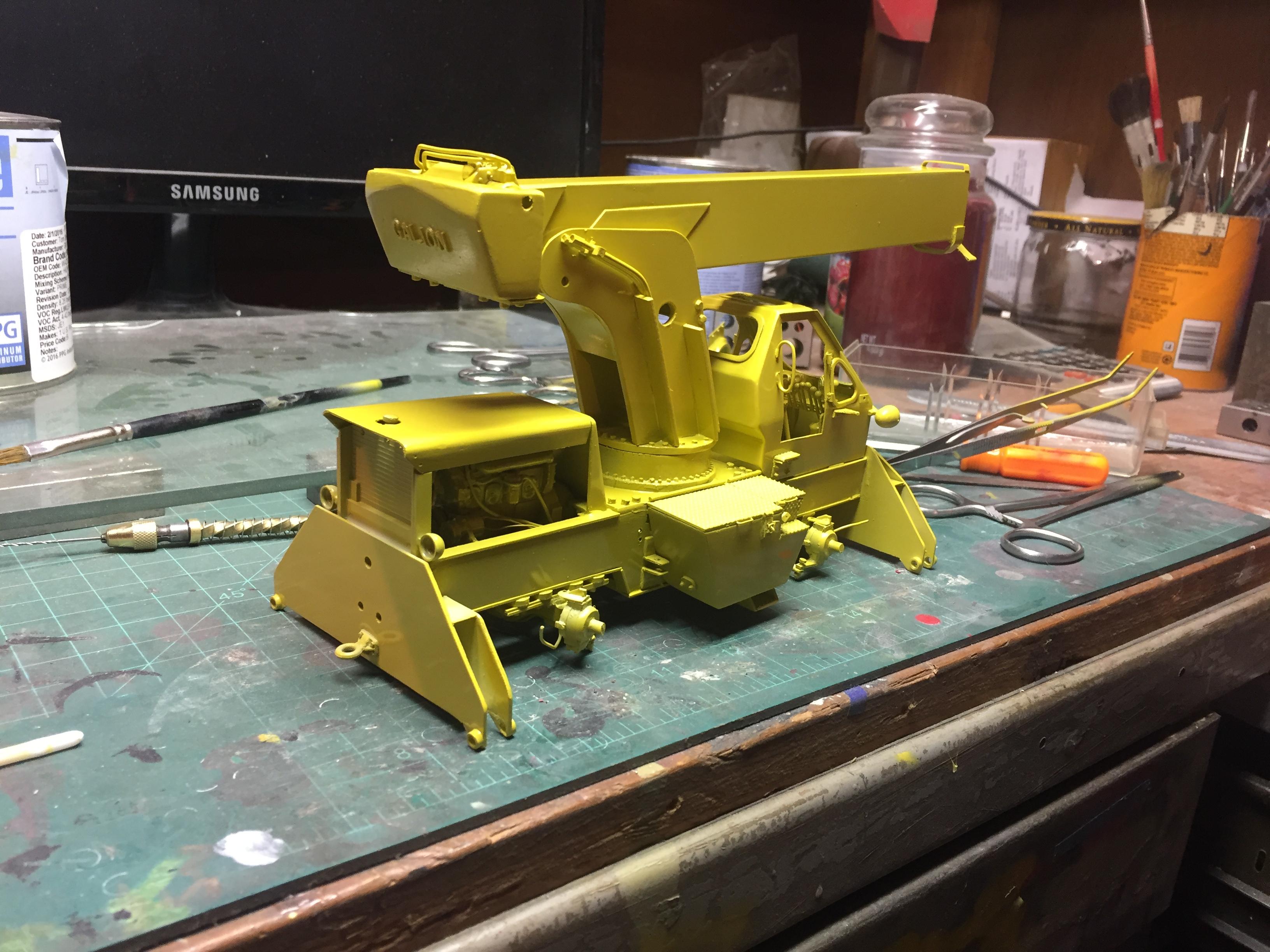
Yellow, finally! Lots of assembly and details to attend to, but looks good!
-
My SOP is to get the manual for ANY of the off the wall builds I attempt first............both operator's and parts manuals. They are priceless when trying to do something like this. I also try to find a real one to photograph and measure. And, by the way, I LOVE your engines and your dioramas....................something I have always wanted to attempt, but just have not pulled the trigger on yet.
-
The five ton military truck would be another real big project, though my inspiration is Charlie Rowley, (Chariots Of Fire), who made a beautiful brush fire truck build of one. I had an M54 for years, and parted ways with it when I closed my garage. It was a VERY handy truck that was just about indispensable around the shop. I have one of the old Renwal/Revell ones in 1/32 scale that could be scaled up rather easily, but, haven't made up my mind what will be next! Gotta get the yellow onto this old girl first!
-
The only problem with getting NEAR the end on this one is deciding what's next! Finishing a build that has stalled, or something new???!!! Got the Eager Beaver detachable neck lowboy to finish, a paver that is just a few manuals and dreams, an M52 five ton military truck, or any one of a dozen other dreams in progress! Perish the thought, but out of the box has become boring!
-
Ha! Don't do that.......your work is an inspiration to me!
-
Yup, and believe me, I seriously had second thoughts when I decided to try them! They surely gave my arthritic fingers a challenge, but, they came out well enough to at least be recognized as what they are supposed to be! Thanks!
-
Coming out of the closet
redneckrigger replied to countrypapa's topic in Welcome! Introduce Yourself
Welcome to the forums, Bill. This is a great hobby, and the beautiful part of it is, that you don't have to please anyone but yourself. I build all kinds of stuff, and sometimes spend LOTS of time at the bench, and then go a couple months with no time at all spent. My builds are only to please myself. I like sharing my builds and experiences and ideas with others, but at the end of the day, only one person has to be happy with my efforts................me. Enjoy the forums, and the superb company found here! -
Very nice work so far! The day cab is more interesting to me than the more commonly seen sleeper. Keep the photos coming!
-
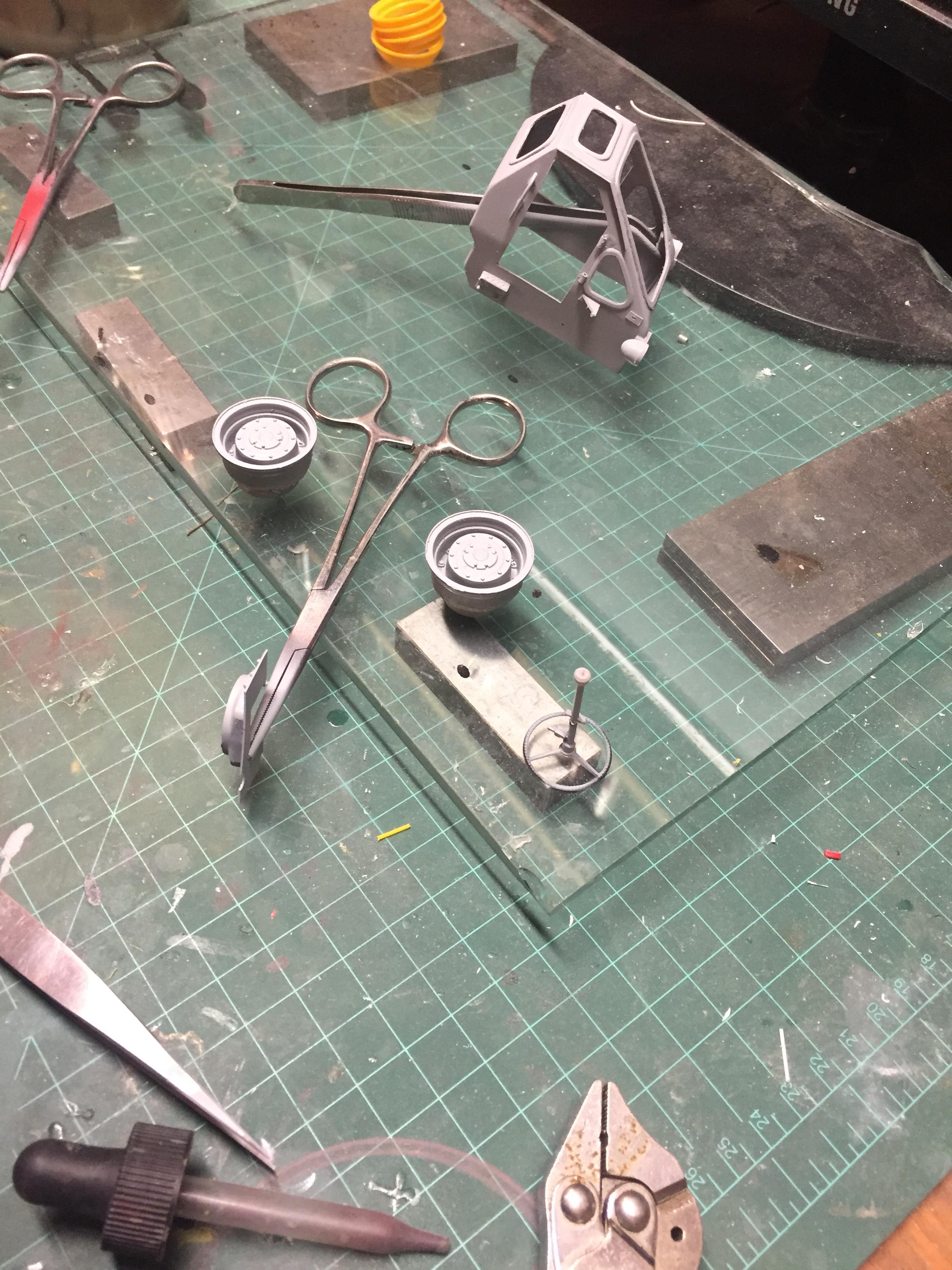
PRIMER!!!!!!
-
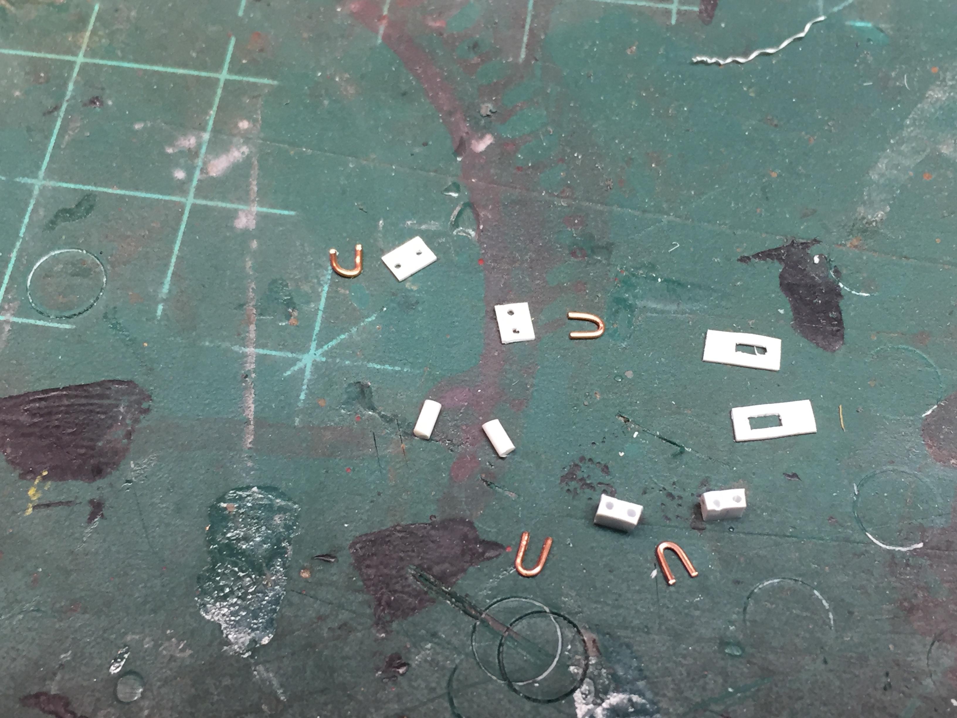
Of course, there's always that one more detail to add..........gotta keep the lowlifes out of the tool boxes! Hasps and locks. A true test of patience! Add a couple steps and a drip edge on the cab and a boom angle indicator and I THINK I've got all of the details done!
-
Ready for primer and paint!!!
-
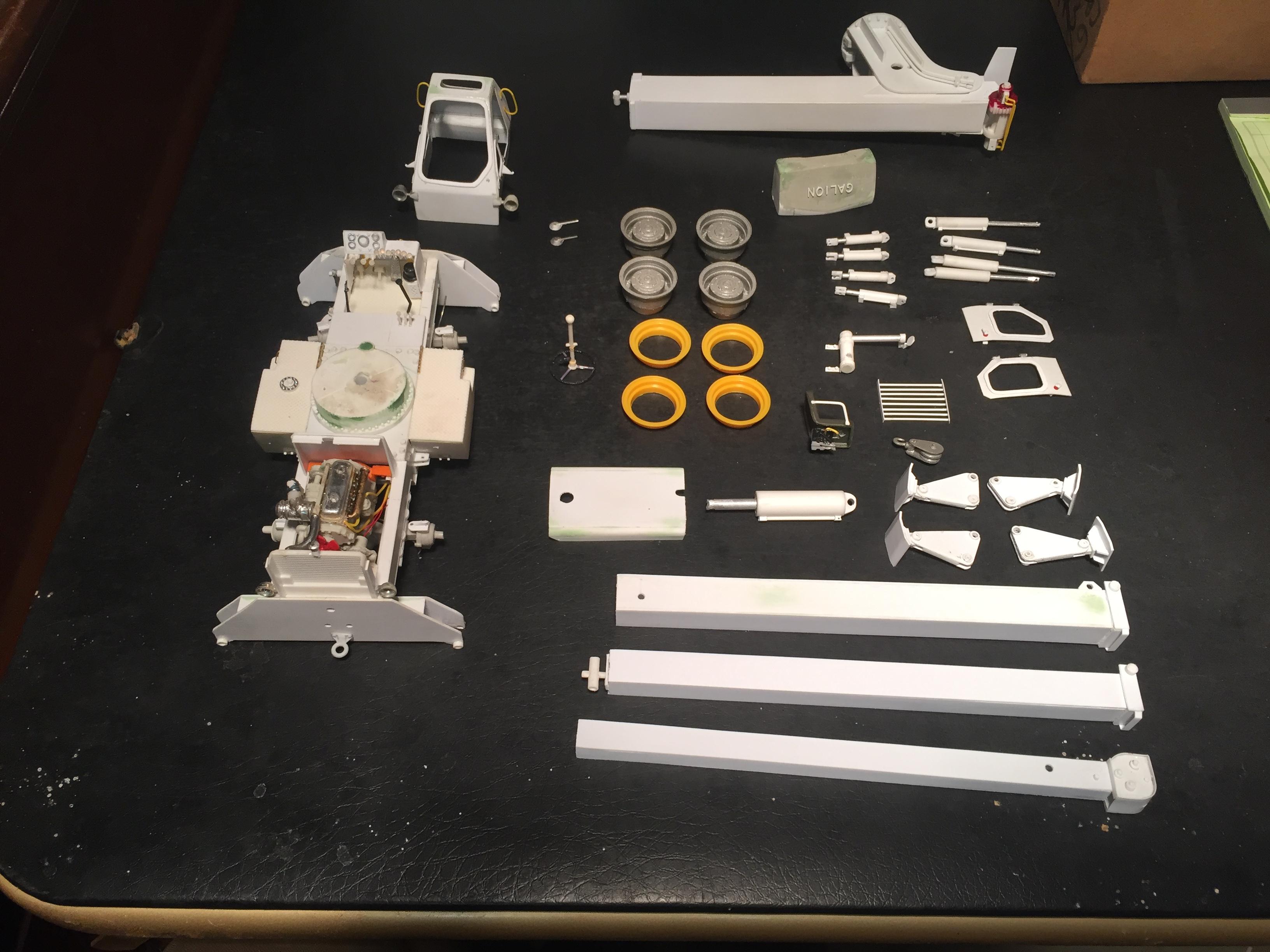
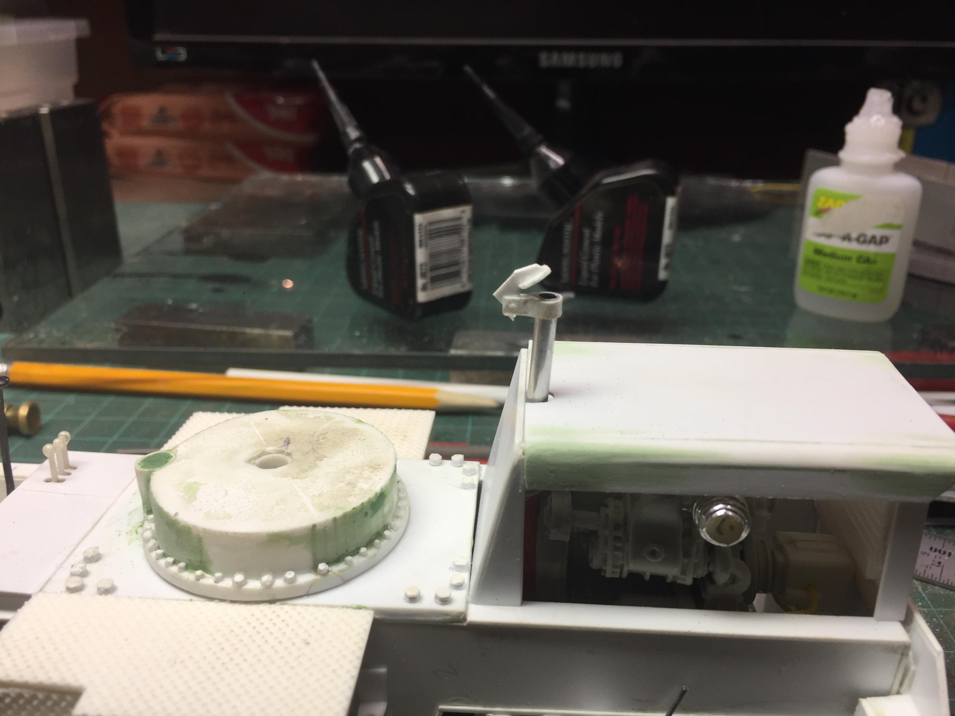
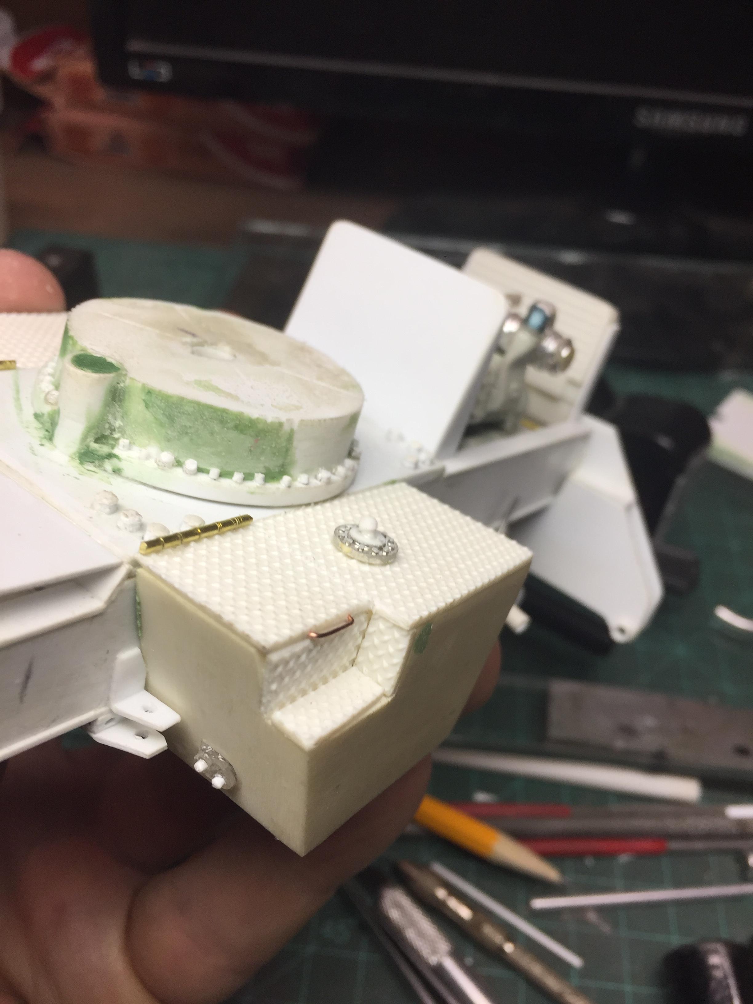
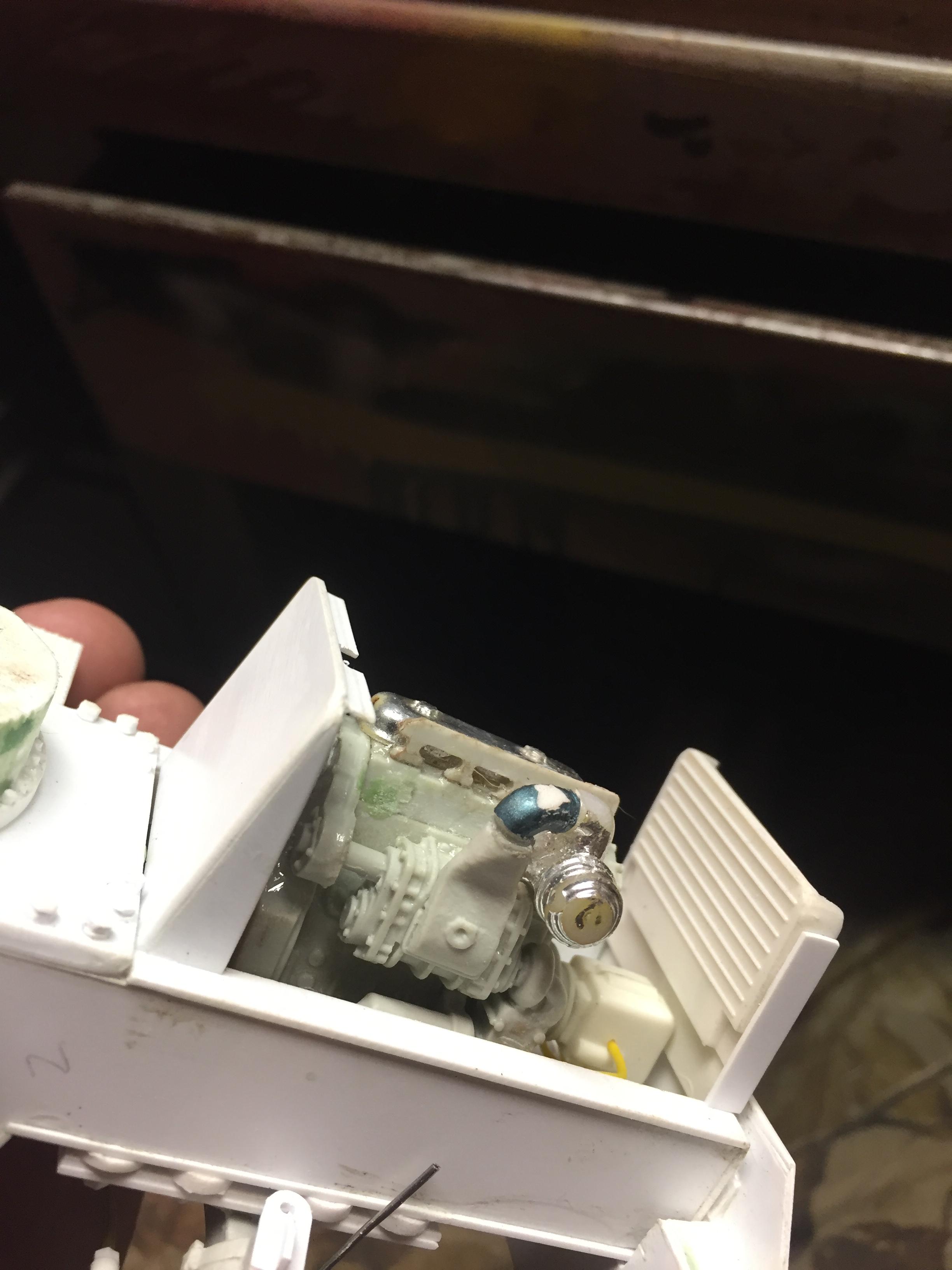
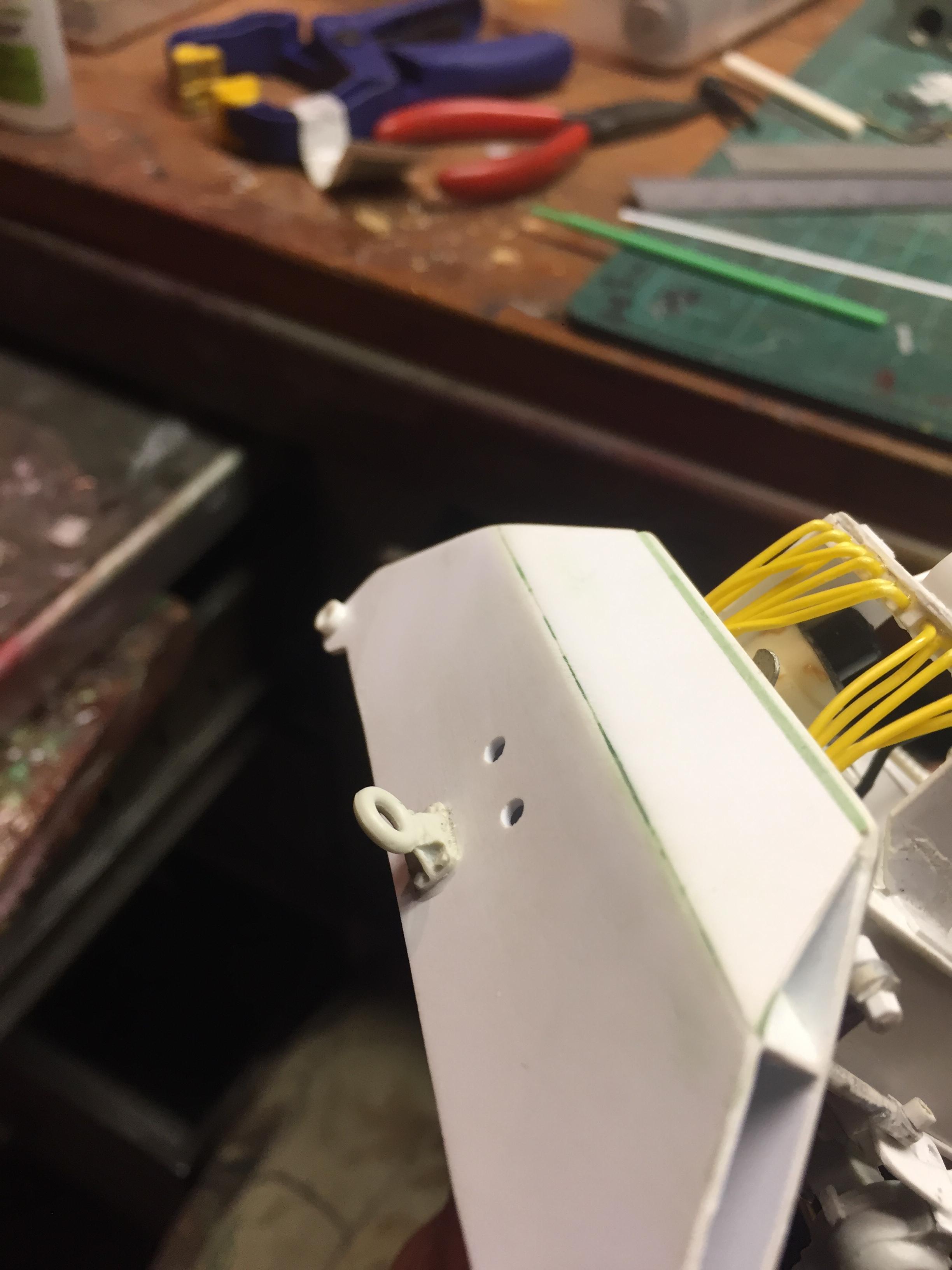
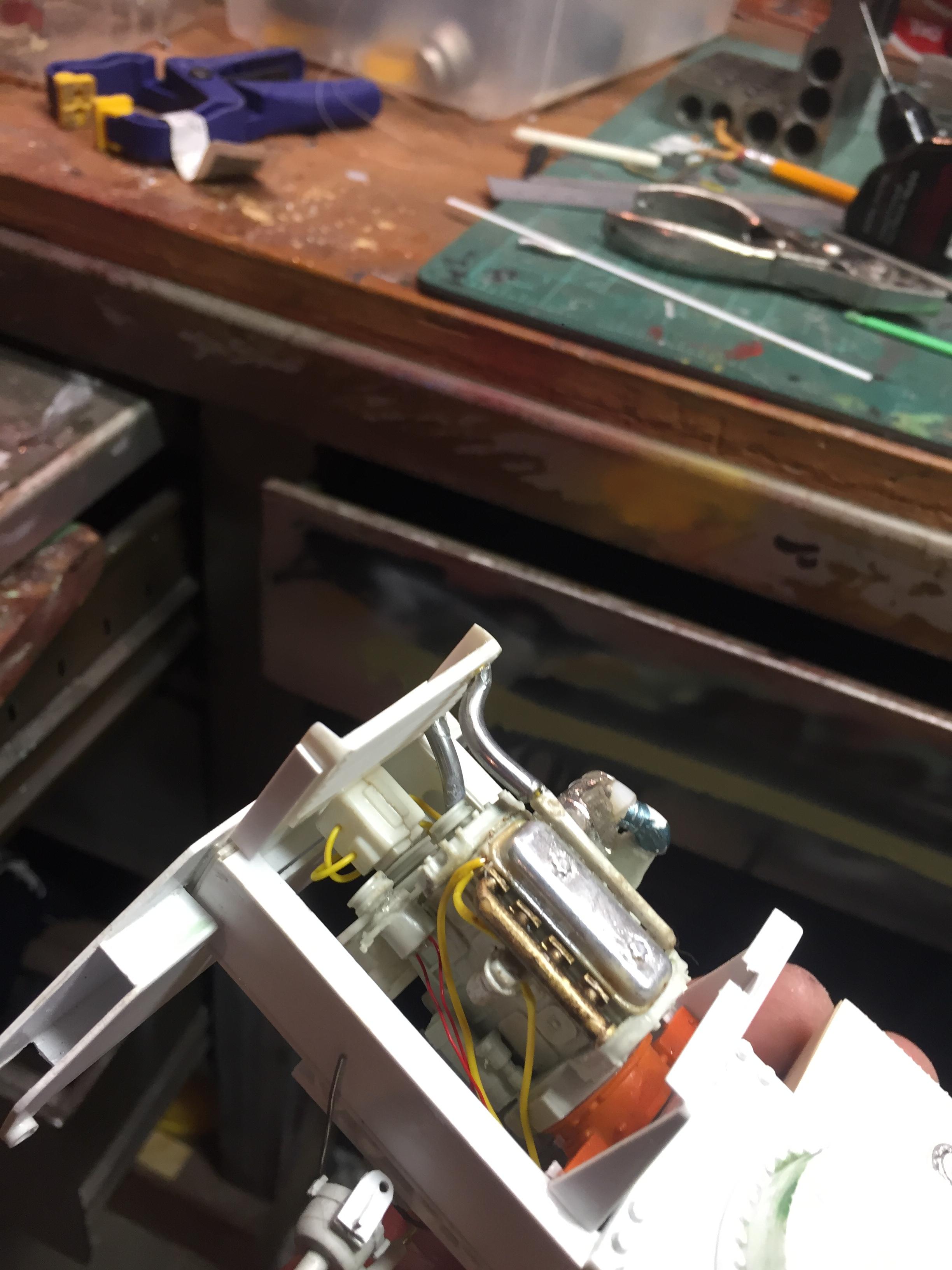
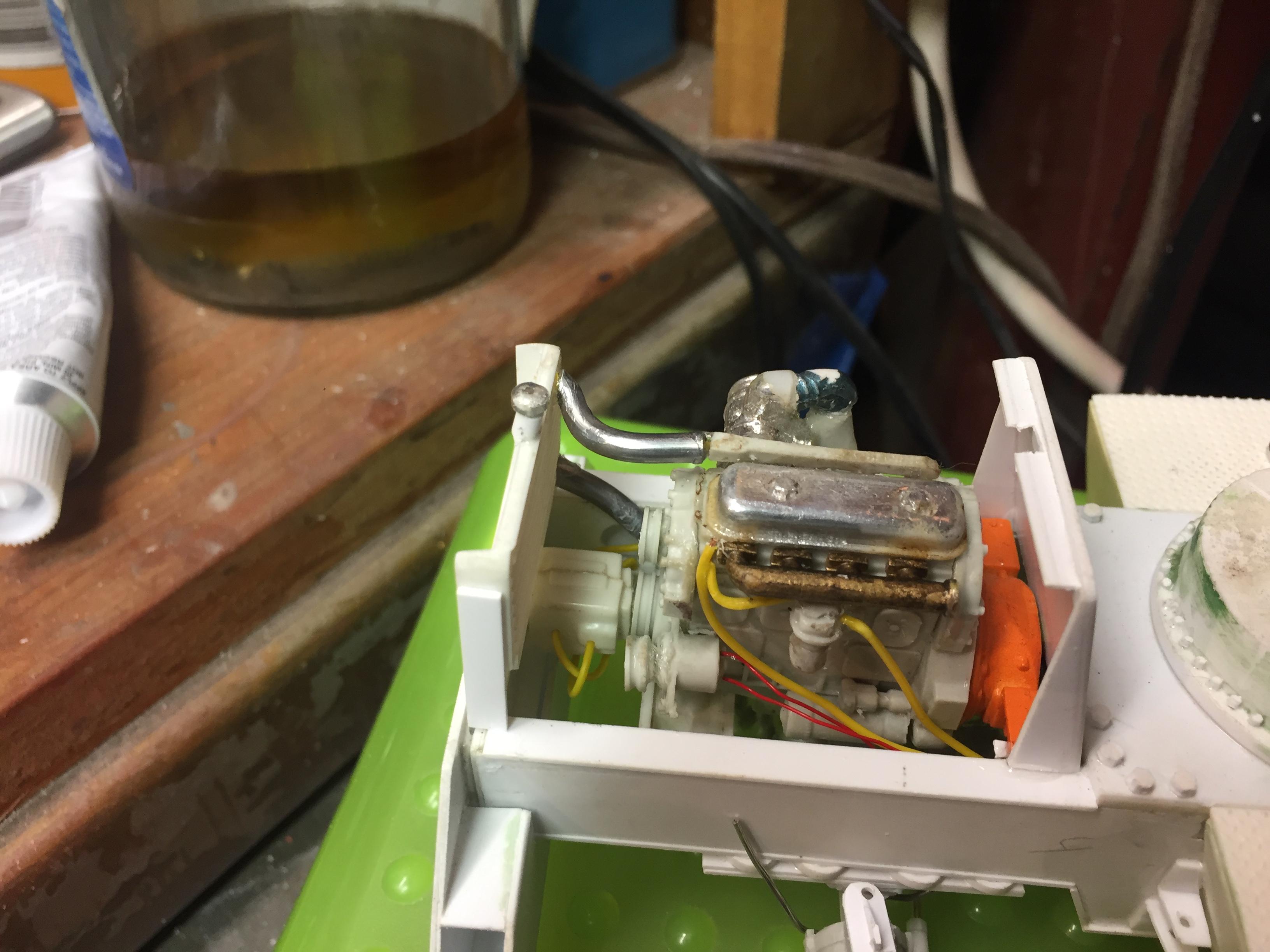
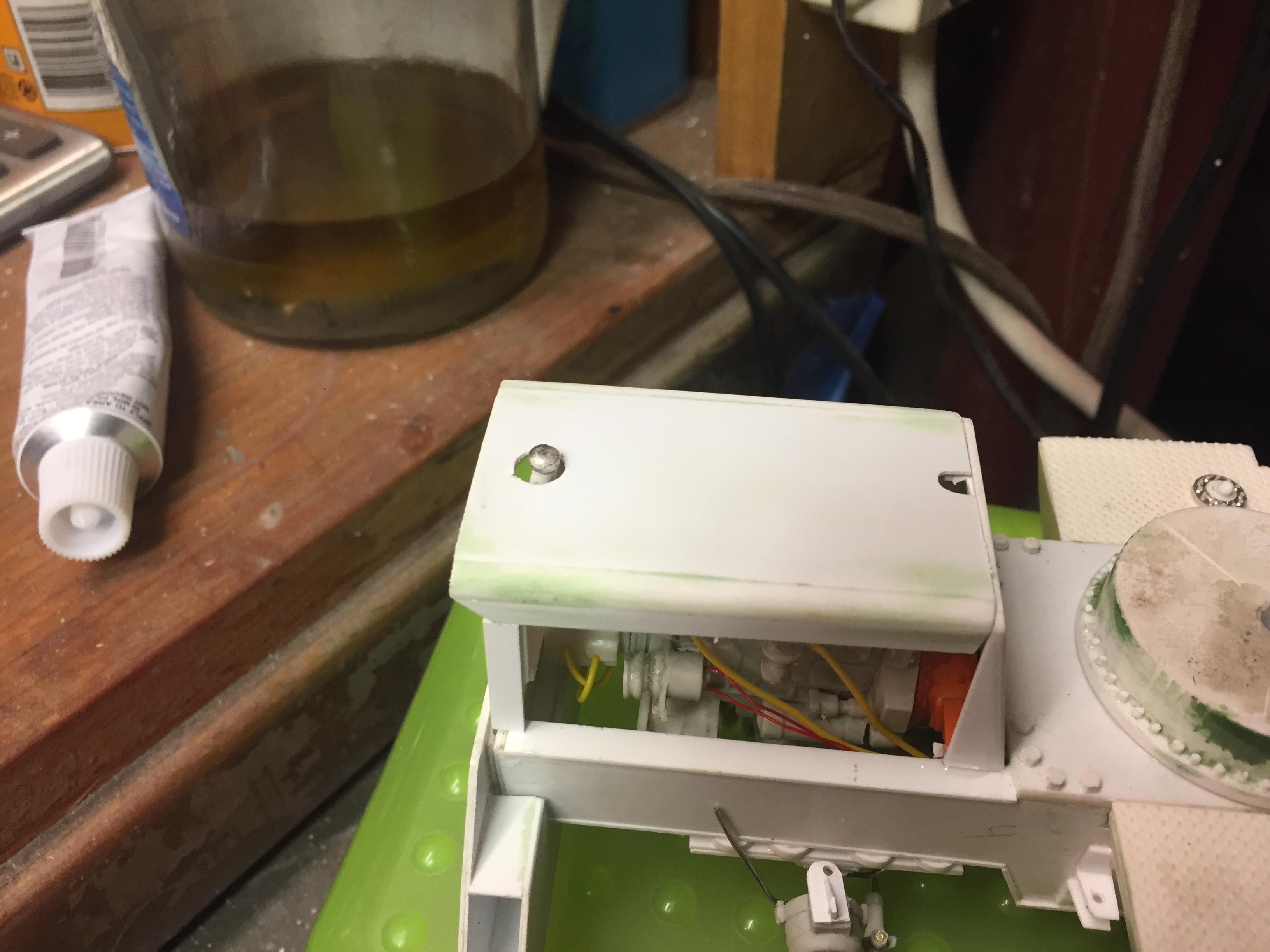
Spent some time adding details. Added grab handles to the cab, hinges and handles to the fuel tank and battery access lids, installed the engine, added fuel lines, coolant hoses, fan and shroud, radiator cap, air filter, door stops, mirror brackets, head and tail lights, made the exhaust system, (the muffler Is not hollow, but it's filled with a clear lucite rod to make it solid.....it just is an illusion), cable retainers on top of the boom, LOTS of nuts and bolt details to the axles, turntable, swing gearbox and everywhere else that looked naked, hook travel tie down, hydraulic and fuel tank drain covers, hydraulic fill cap, and a LOT done on the punch list! Getting VERY close to paint now! There will be a LOT of subassemblies to paint separately then a lot of assembly time but the light at the end of the tunnel is actually visible! Guess it's time to mix some Galion yellow paint!
-
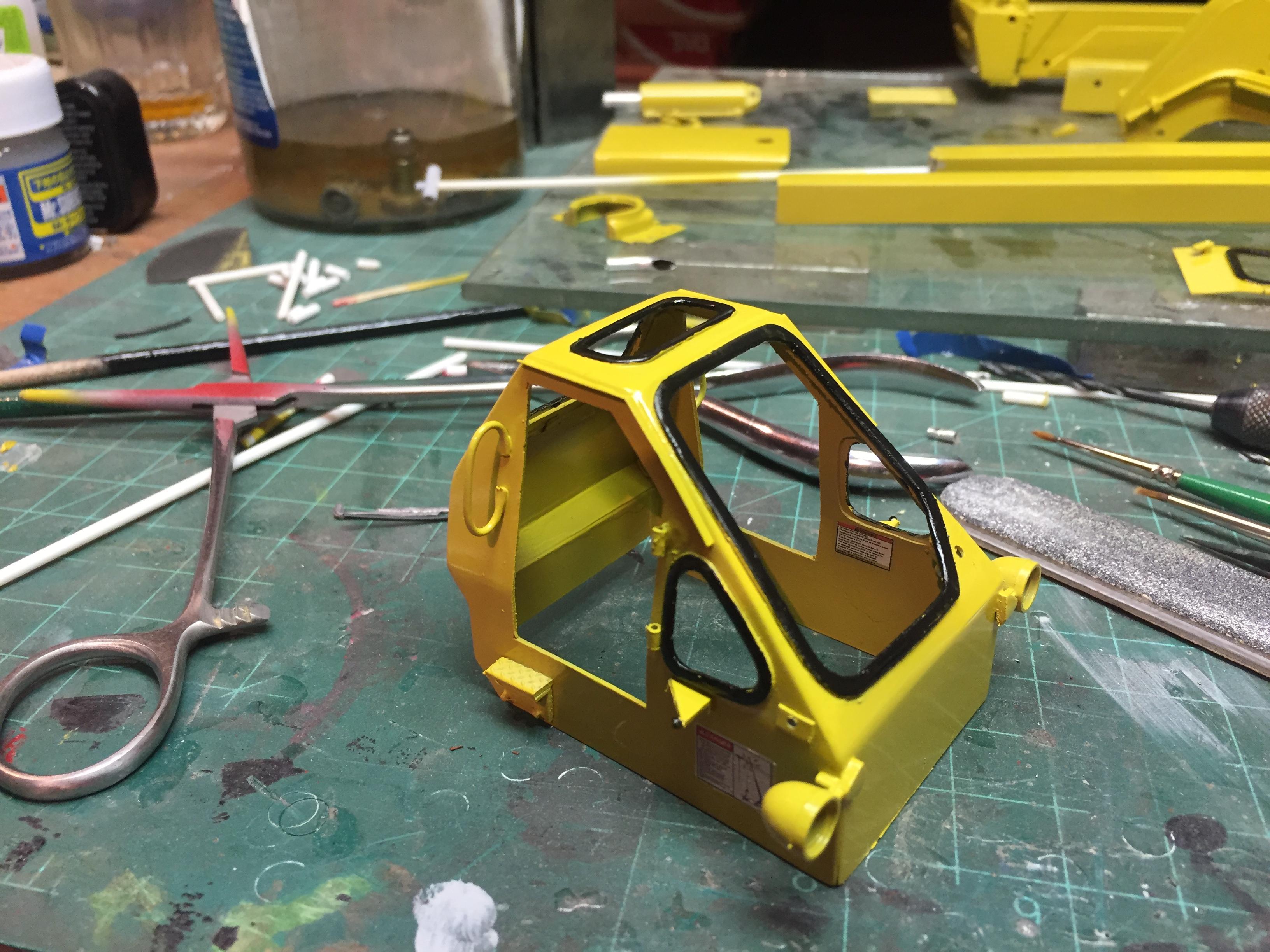
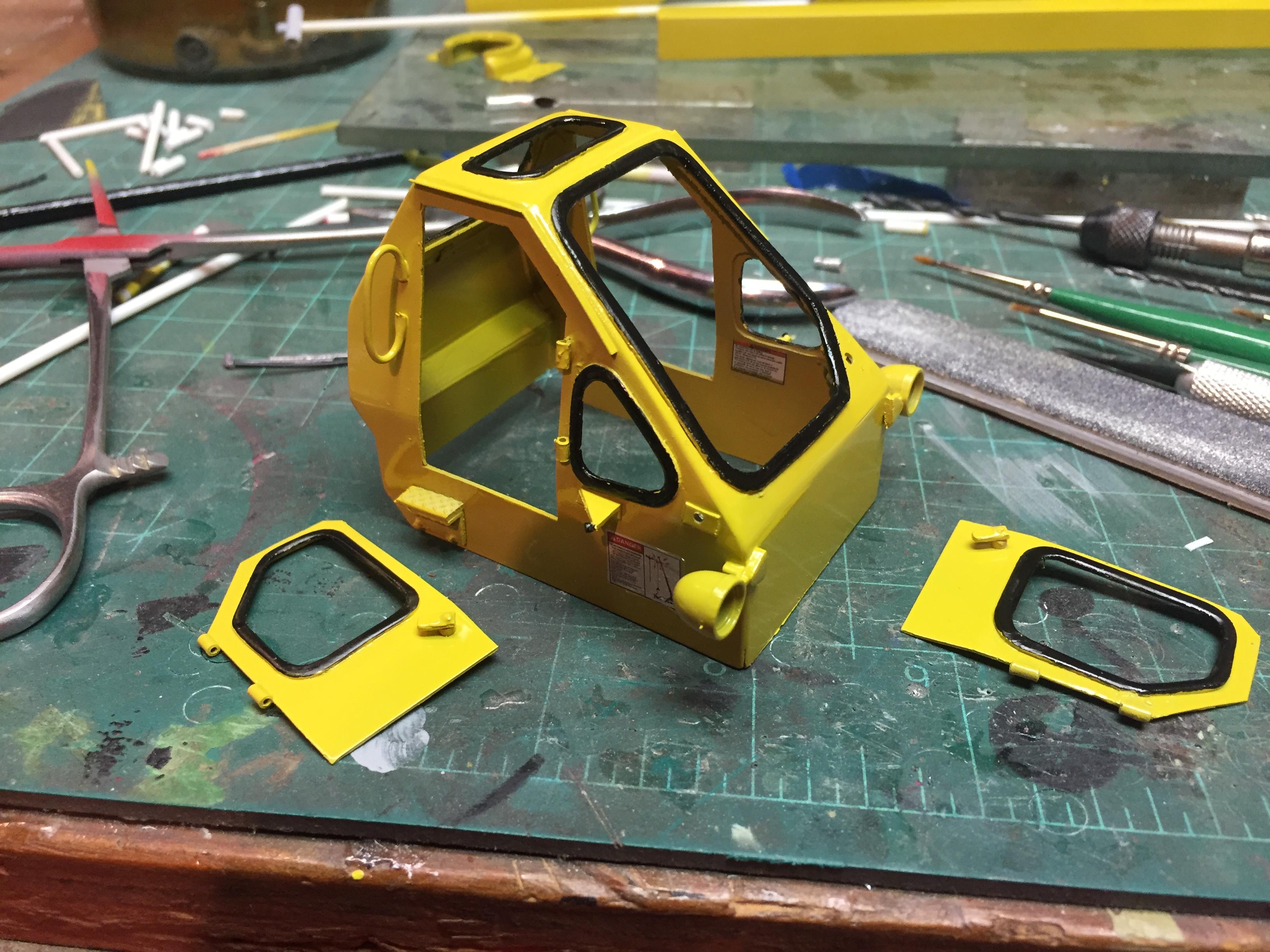
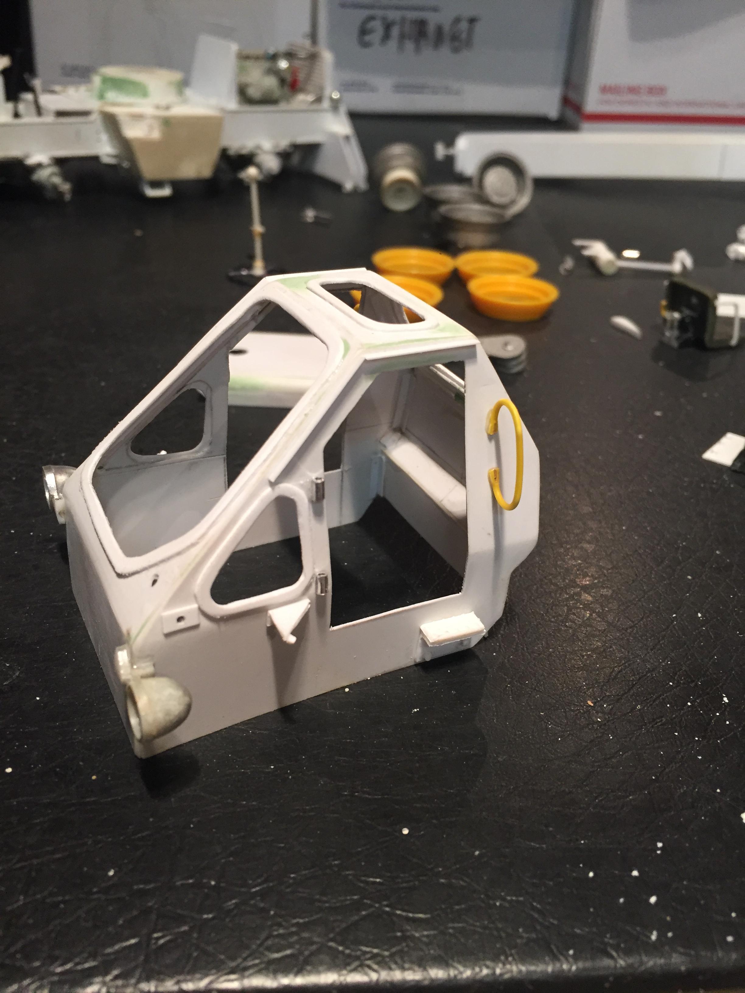
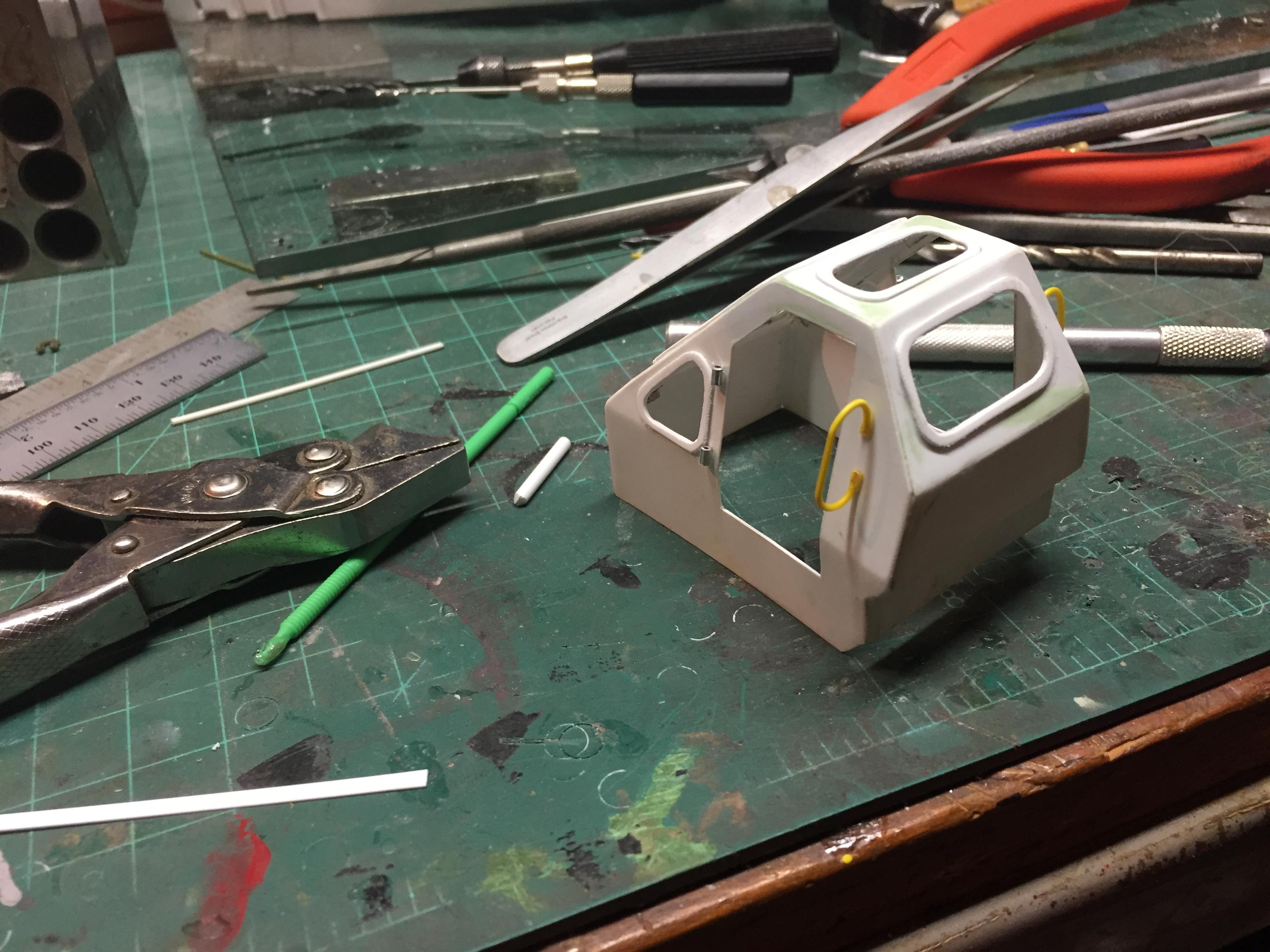
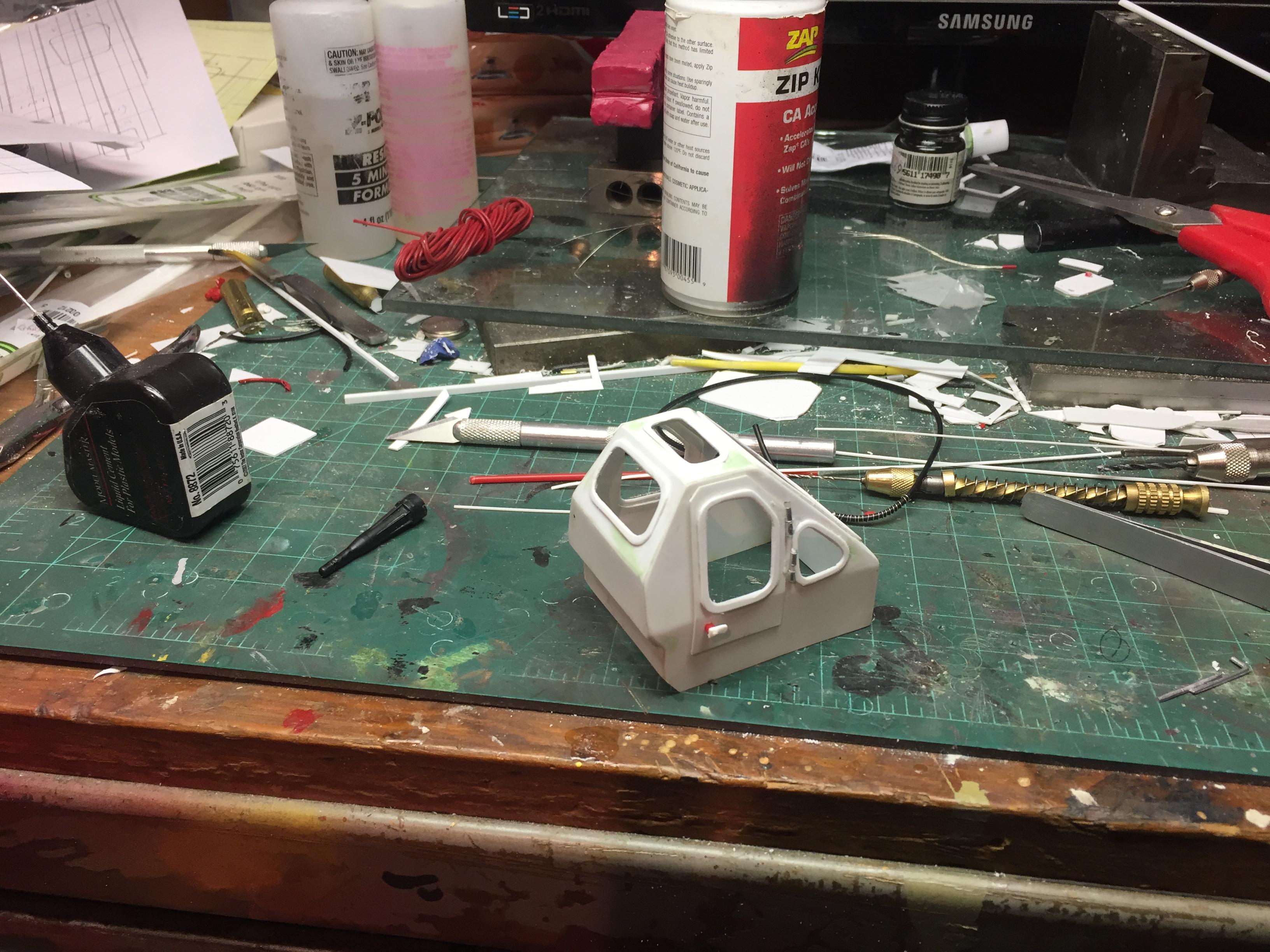
Attached the gaskets to the cab......will paint them after the cab gets painted. Looks decent so far!
-
Thanks Charlie! I am going to experiment to see which one my shaky hands can handle but it does look like attaching them before paint and them blacking them later is the way to go.