Chariots of Fire
-
Posts
2,782 -
Joined
-
Last visited
Content Type
Profiles
Forums
Events
Gallery
Everything posted by Chariots of Fire
-
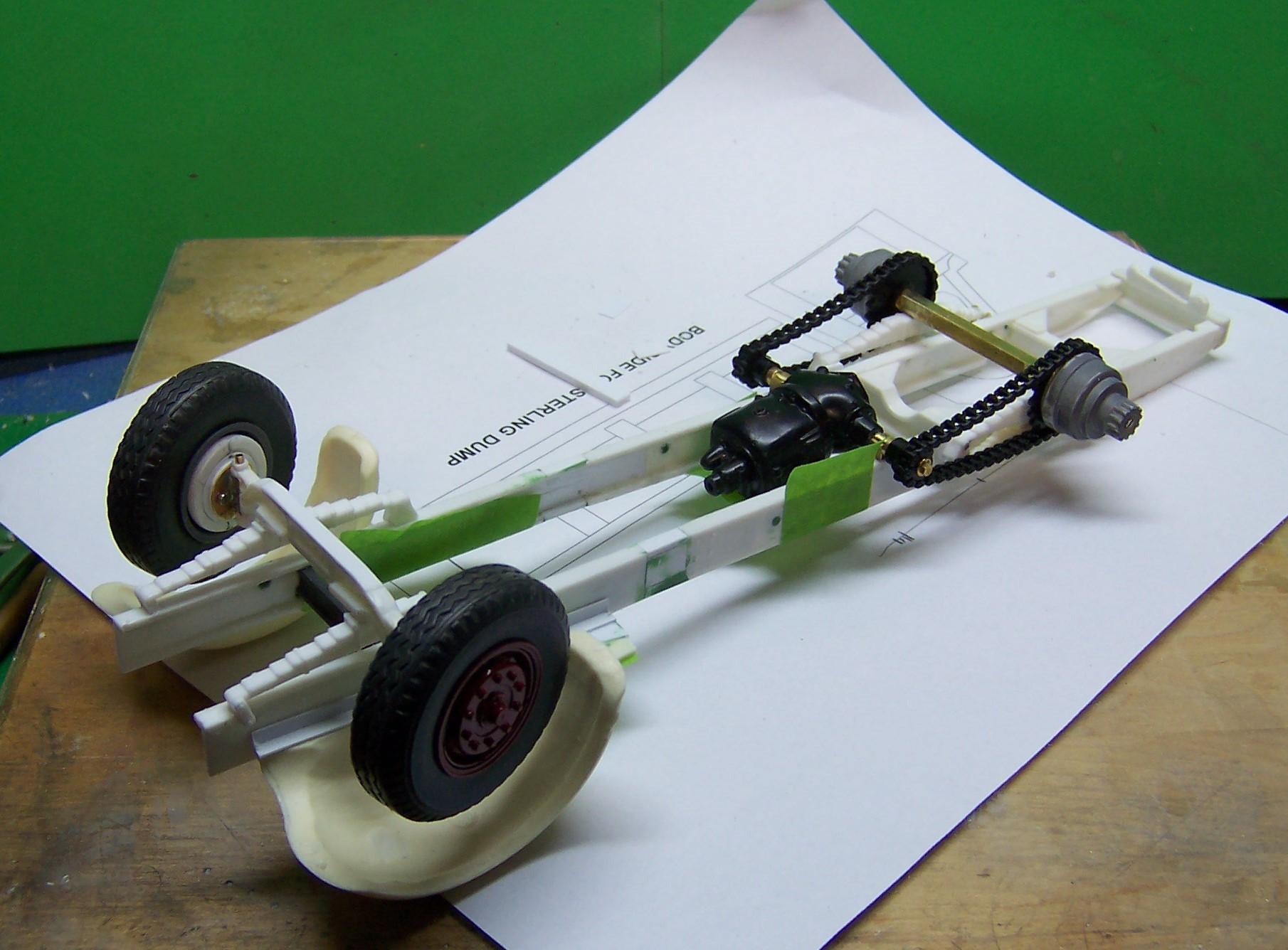
 Hey, Tom can I make a suggestion: Get either some aluminum or brass tubing, make two bearings for the walking beams and then slip the next size down tubing in as the connection between the two sides. As you build, the weight is going to get more and more on the plastic rods you are using now and could in time deform or break. I'm liking what I see for sure!
 -
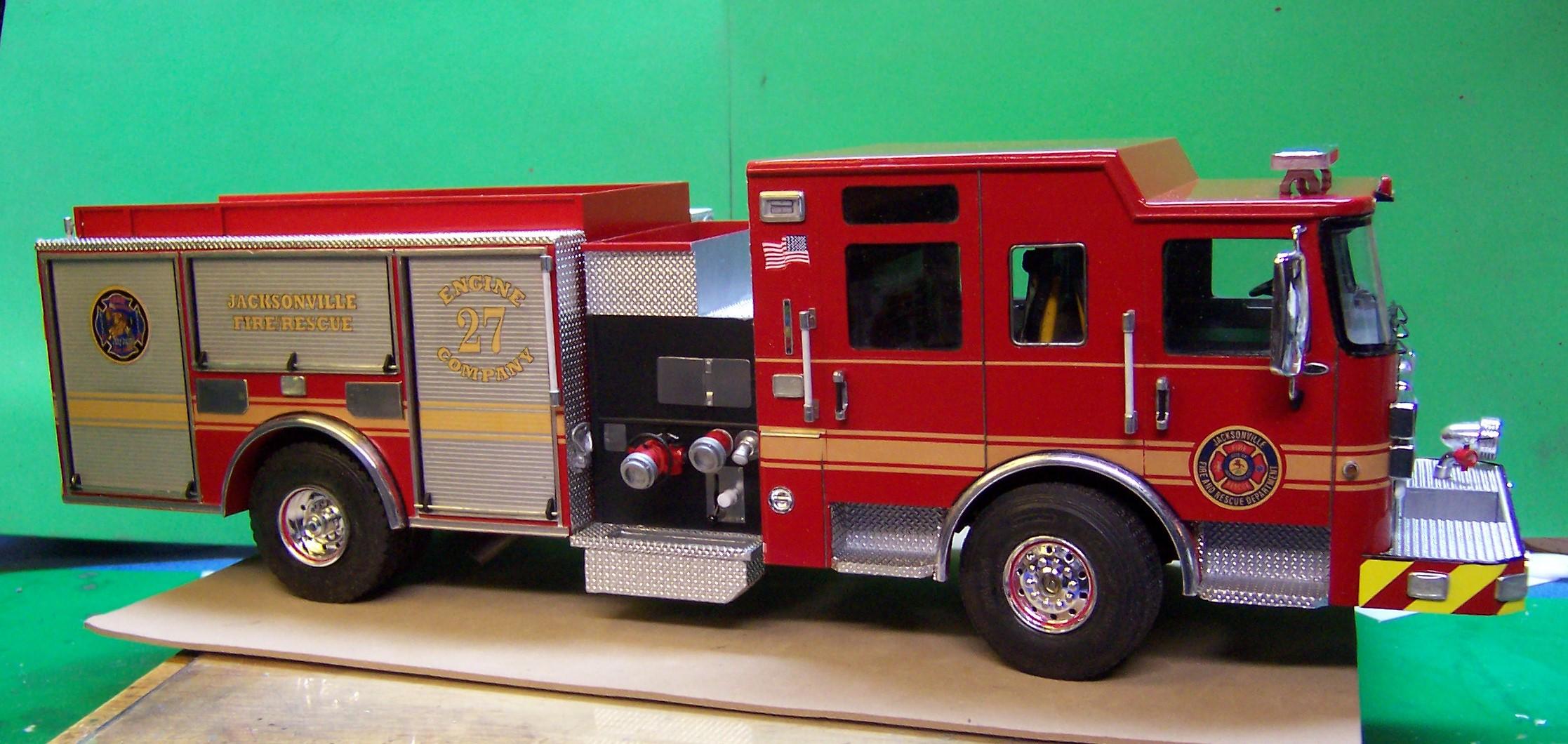
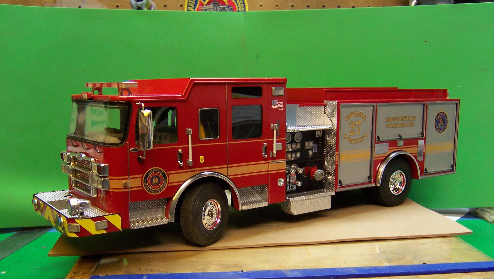
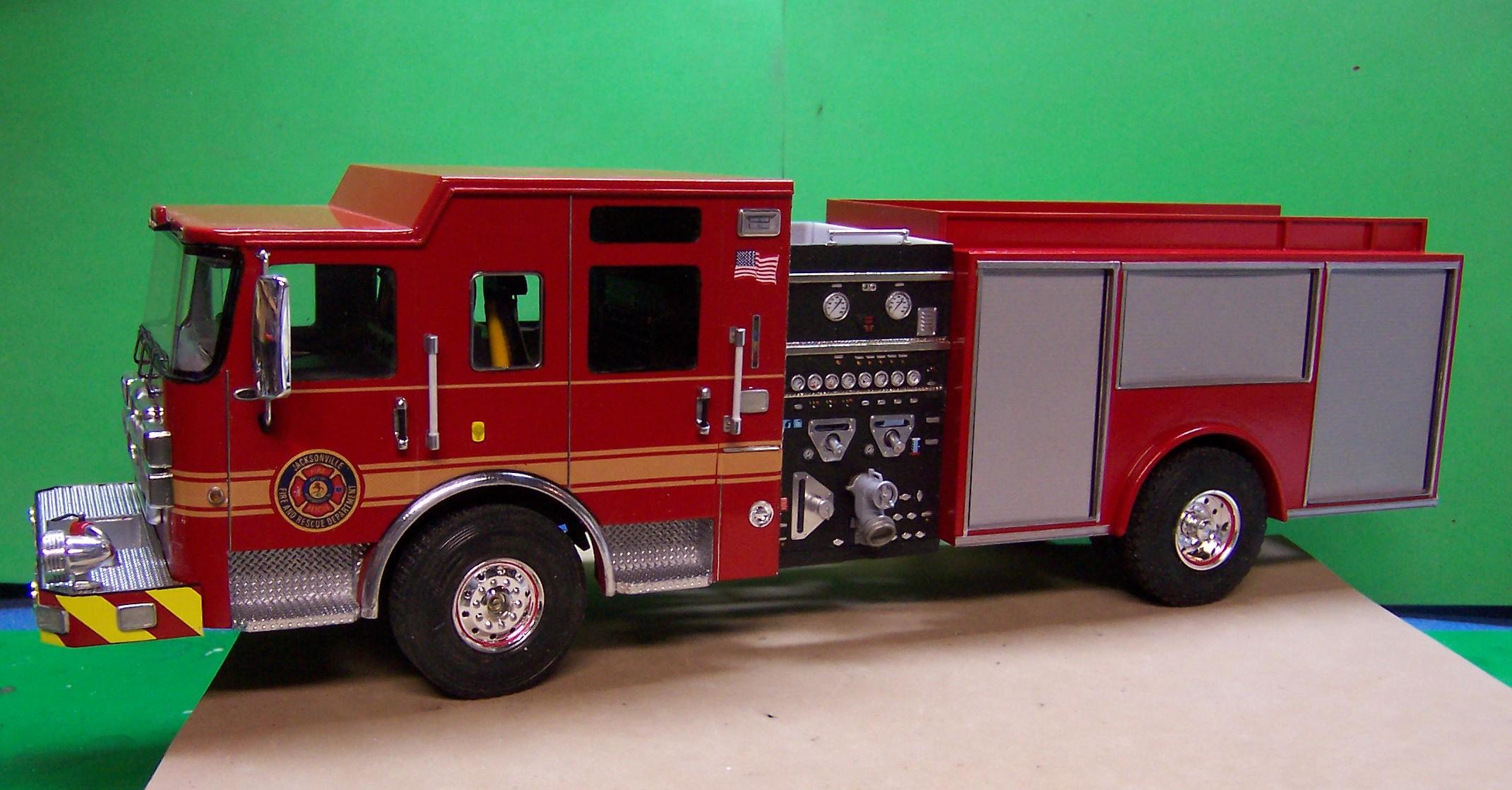
And here's the right side. No where near as busy. Just a few small items to add and this part will be done.

-
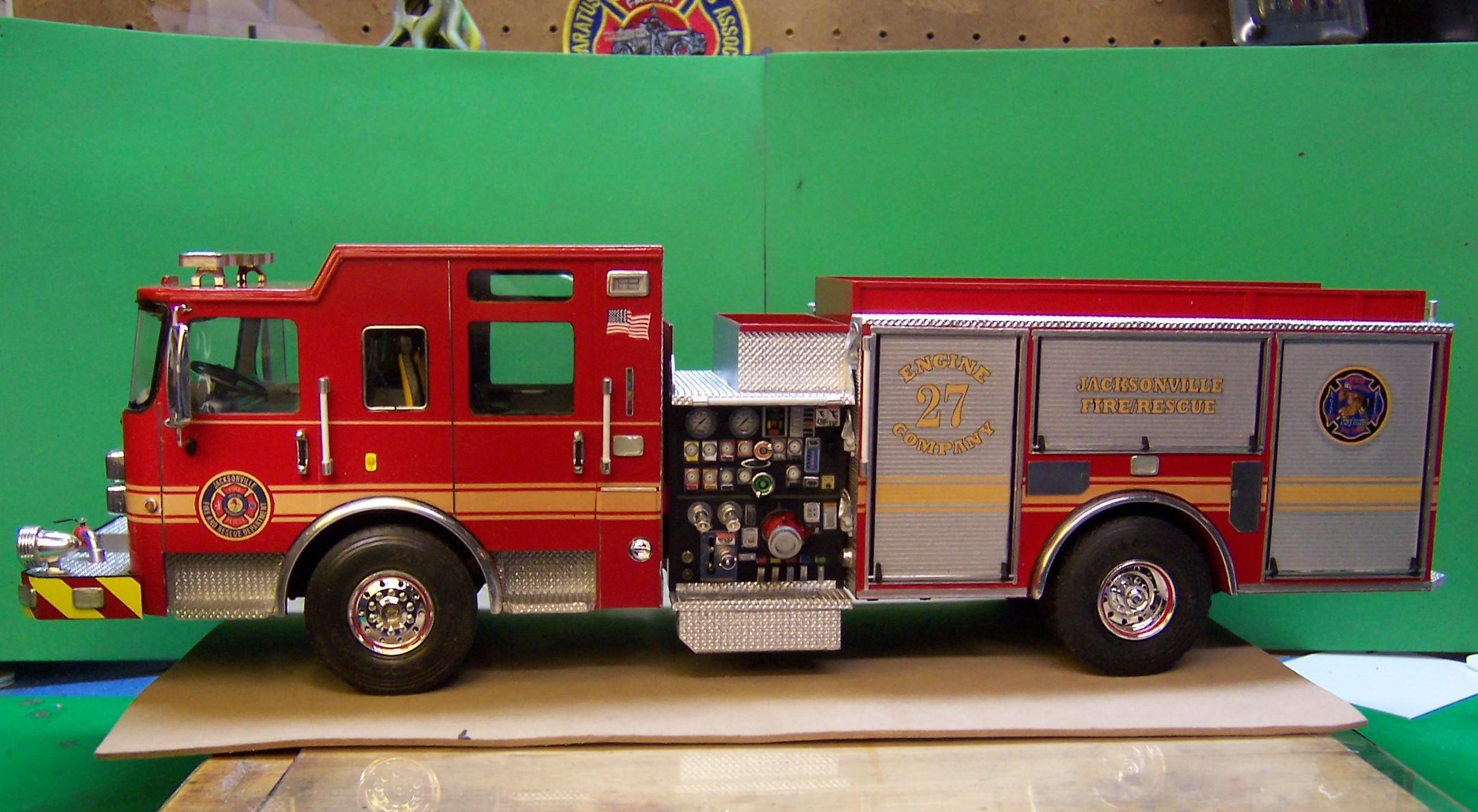
Just an update on the pump panel progress. I'm calling the operator's side done. Now it's on to the officer's side. Then there's a booster hose reel to make and a hydraulic ladder rack. Oh Fun!!?
-
Definitely a chain to pull the plow up. And there would not be much vinyl tubing visible. Small hydraulic cylinders would push the blade from side to side as well as a cylinder to raise and lower it. I've got some photos also that might help if they are needed.
-
That's nice work! Excellent craftsmanship.
-
RM Mack w snowblower....
Chariots of Fire replied to gotnitro?'s topic in WIP: Model Trucks: Big Rigs and Heavy Equipment
Sounds reasonable, Warren. -
RM Mack w snowblower....
Chariots of Fire replied to gotnitro?'s topic in WIP: Model Trucks: Big Rigs and Heavy Equipment
Great Photo! What are those primer colored plates on each side? Reinforcement of some kind? -
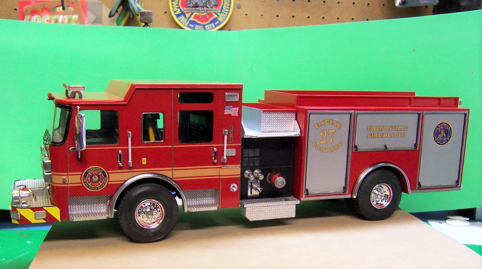
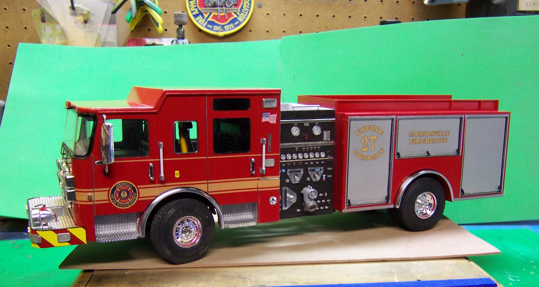
Progress continues one little detail at a time. So many of them yet to do! Striping is finally done. Working on the pump panel with still some items left to put on. Then I have the whole right side of the panel to do. Folding steps are mounted back of the panel, SCBA doors installed and the diesel fuel door has been added.
-
There was a seated driver in one of the Italeri customizing kits for trucks. It's 1/24 scale but would fit your need. Try looking for G scale animals on some of the railroad websites. You might find some there.
-
I like the stubby nose look. I'll be watchin'! ?
-
Ever use Duplicolor paints? They make a good filler/primer in gray. They colors a great and go on in a very fine mist. Takes time to build the color up the it dries fast and hard. It can be sanded and it polishes out great. All are about $10/can.
-
Thanks, Dan. Thank goodness for lots of photos and the spec drawings to give me some dimensions. Experience in the fire service has helped a bit also.
-
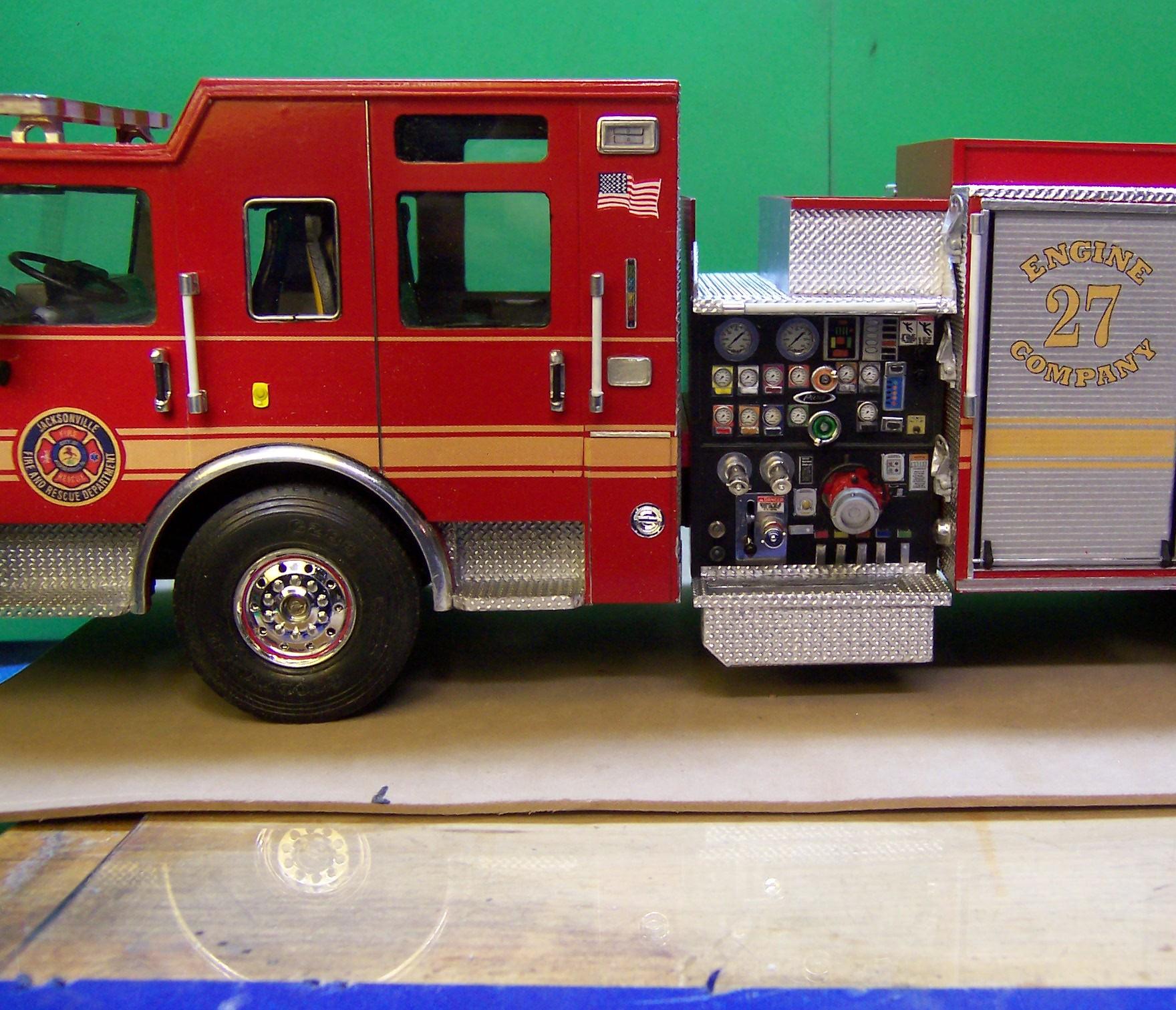
Here's the work so far on the pump panel. It doesn't look like much yet but there is so much to put on it. Used to be an intake, a couple of discharges, a vacuum gage and pressure gage were about all that were there. Oh, yeah, they needed a throttle and tank suction. That was about it. Not now! Every button, gage, valve, switch you can think of. Ah, but I digress. There is still a lot to do on the panel and more on the back as well but we're getting there. The folding steps in the rear are not quite like the Pierce ones but when you have a mold for casting them to my way of thinking they are close enough!?
-
Yup! There will be a floor pan to fill things in once everything is located properly. To do that now would limit the places a long the frame that I could tie the cab, pump panel unit and body down well. Working on the pump panel itself now.
-
RM Mack w snowblower....
Chariots of Fire replied to gotnitro?'s topic in WIP: Model Trucks: Big Rigs and Heavy Equipment
Seeing how things come together is part of the fun. Love what you are doing. -
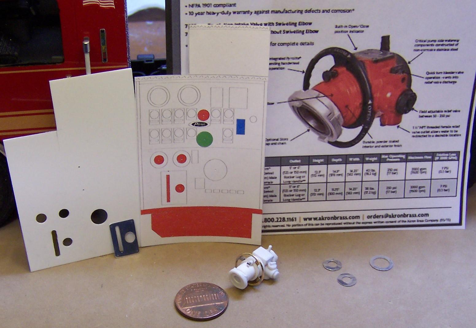
Began work on the pump panel unit. I made up an initial one but decided to set that aside and do another one just a bit wider. Although there are significant spaces between the cab, panel and body and they looked in scale, the gaps were just too wide for my taste. So I added 2mm to the width of the panel to close them up some. It's a busy panel and there is a lot to do but here is the start. That's the beginning of the driver's side panel on the left and a printed mockup beside it. There is a lot more than what shows in the mockup that has to be added but these are the major components. The slotted plate on the left is polished aluminum flashing. Similar finishing touches for the discharge lines on the right. In the center is the large intake valve with a Storz coupling adapter on the end. The real one is by Akron Brass. The truncated red box at the bottom of the mockup is for the soft suction hose that gets stored there.
-
RM Mack w snowblower....
Chariots of Fire replied to gotnitro?'s topic in WIP: Model Trucks: Big Rigs and Heavy Equipment
That's pretty cool! -
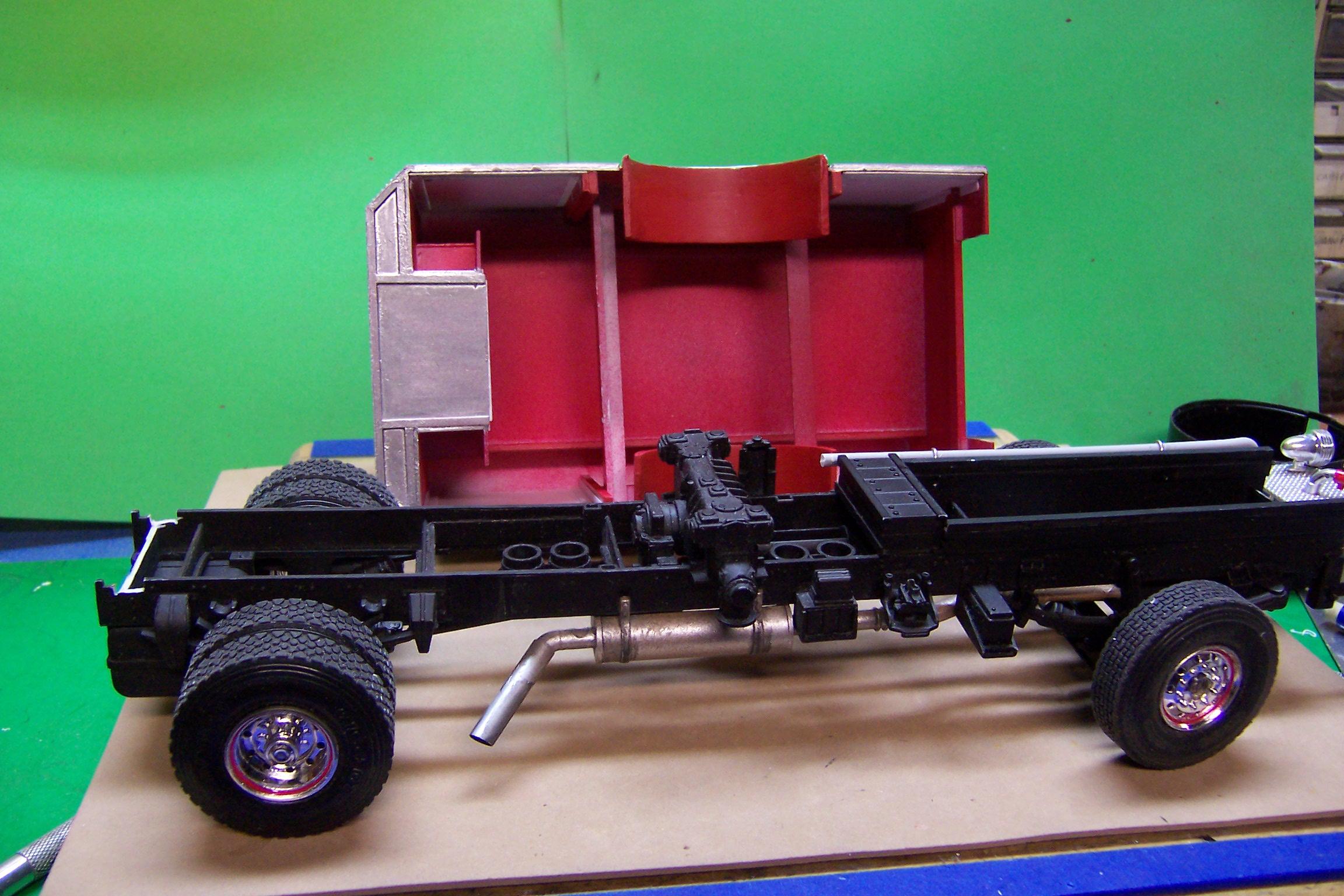
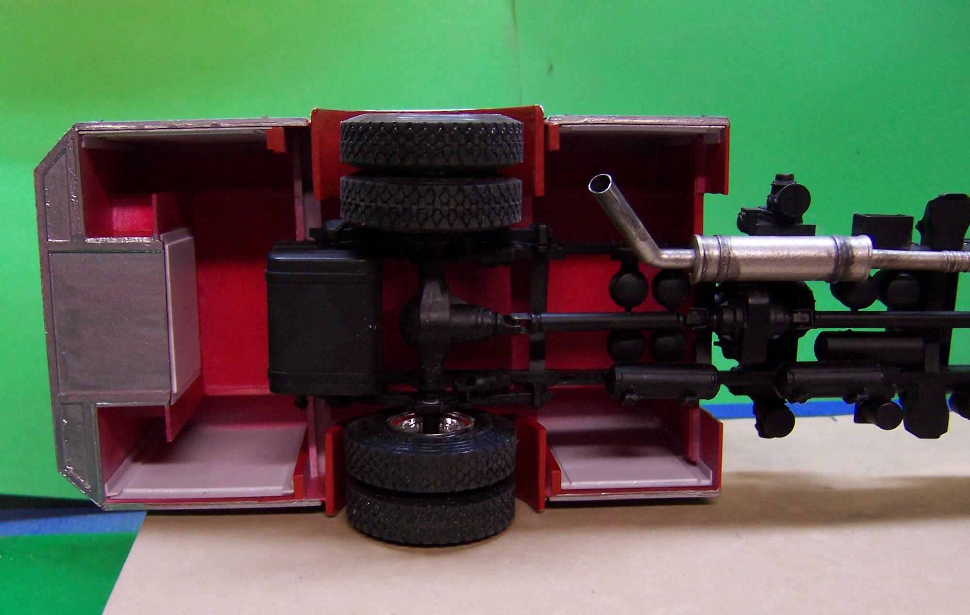
Here's what the underside looks like. Pretty spartan. The body for now rests on the unpainted cross member about 2/3 the way toward the back and the front body panel. Those two points rest directly on the frame. But to get the body to sit level I had to notch out the back of the frame where it is white. Once everything is complete to the point where I don't have to handle the body alone I'll add some connectors to the cross members and to the frame sides and secure the body down well. If I can get screws in there I will do that also. The same goes for the cab. It is only sitting there temporary until all of the doodads are attached. The pump panel is not the panel for the model. Just a direct build from the Trumpeter kit for looks. That whole unit still has to be built. I just painted a piece that will fill in the bottom behind the rear wheels and go around the fuel tank. That will be attached after the body is secured to the frame.
-
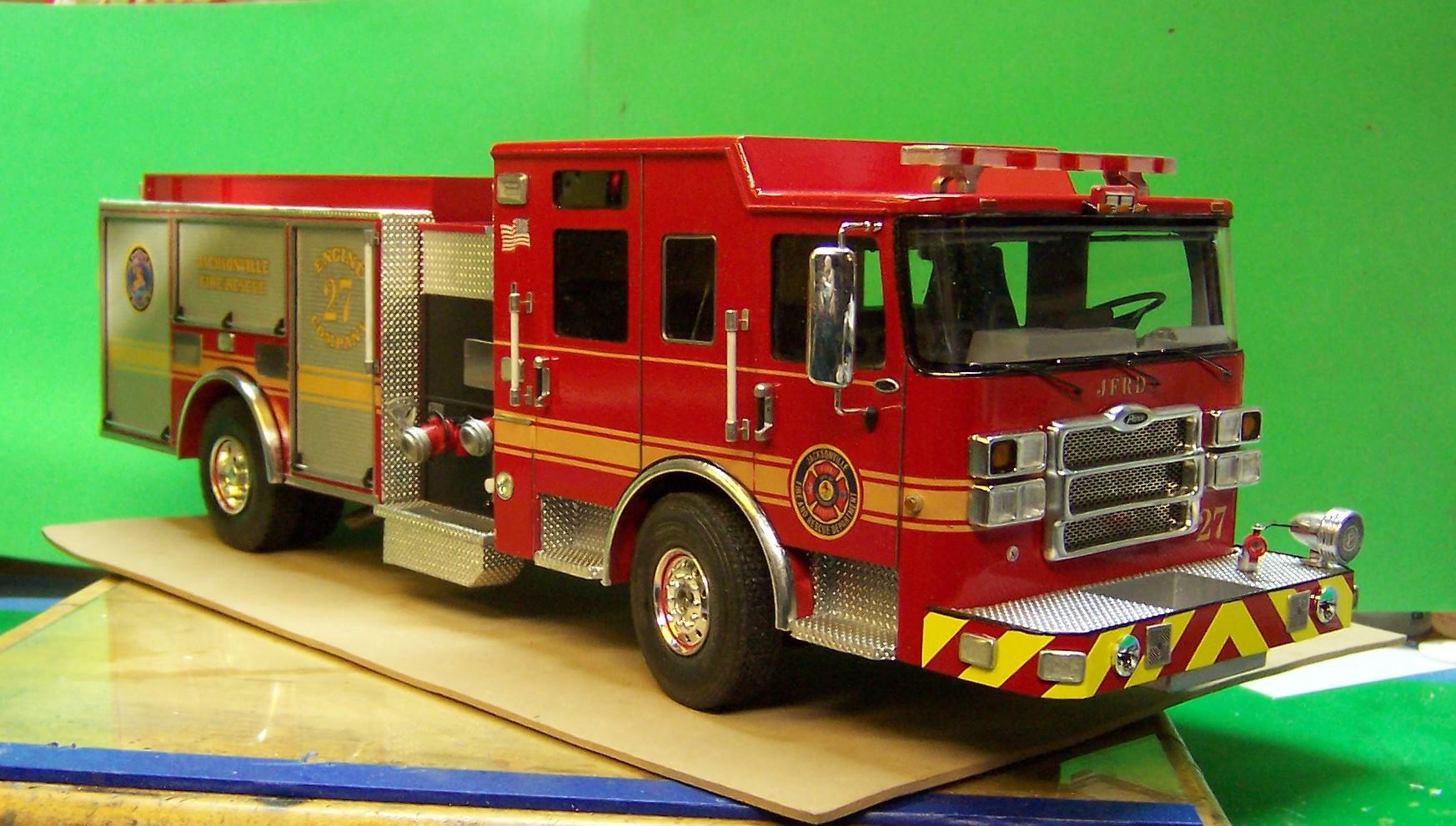
HI, Aaron. Yes, this is definitely a bit more modern that most of what I have built but it has been a good project. Learned some things along the way. Here's an up to date photo. I'll shoot the box and chassis so you can see the underside. Pretty open and uncluttered but many pieces.
-
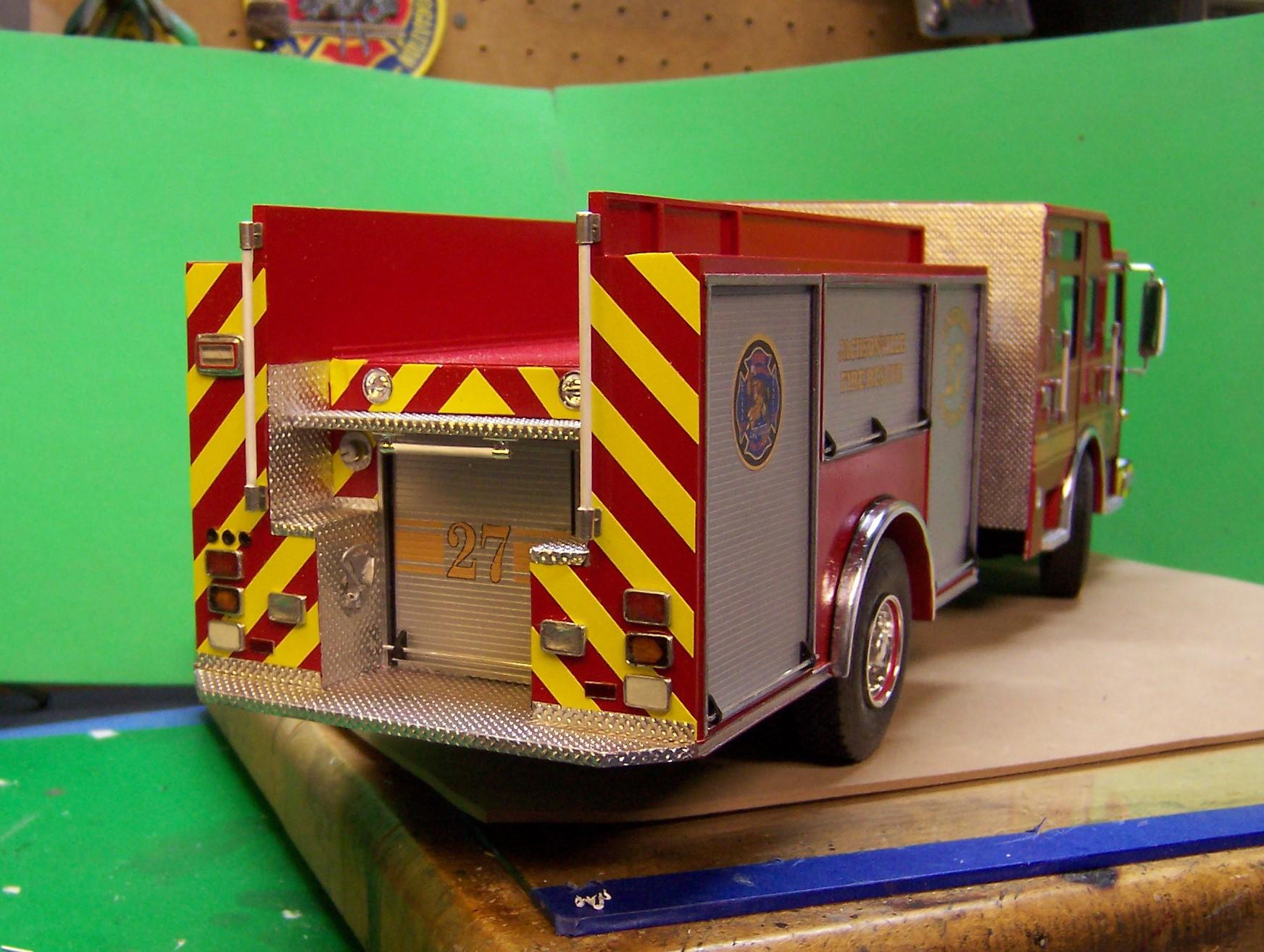
They slide in from the bottom and fit against the inside of the body and the stiffeners between them.
-
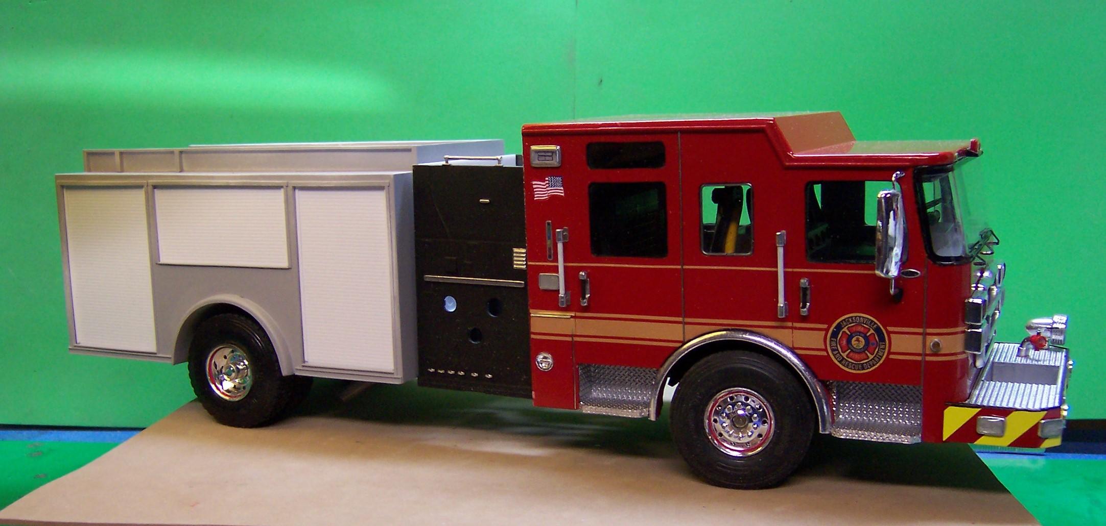
Here's what it looks like with some paint on the body and the roll up doors set in place. Not permanent yet; just for show. Still have to BMF the rear wheel wells but the silver paint needs to dry good first.
-
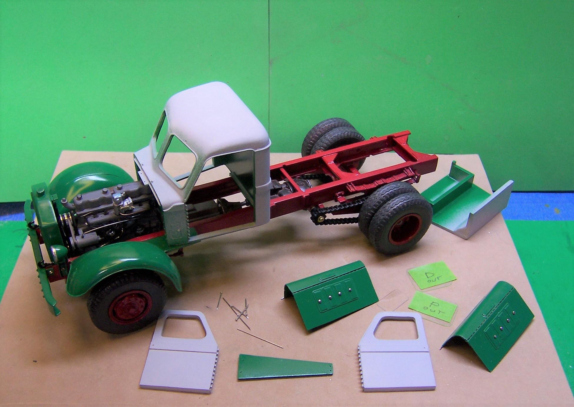
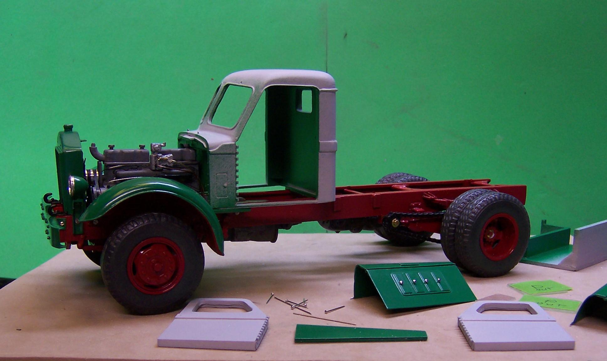
AITM resin kit of the Sterling has separate fenders that need to be attached to the frame sides. Since my Sterling is an East Coast version I cut about 1/4" off the bottom of the hood sides and cab. that made the cab sit lower on the frame. The fenders then can attach to the frame with the flat part flush with the frame top. A look from the bottom. I attached a piece of Evergreen angle to the fenders and then drilled holes through both the angles and frame sides for small screws. During building I was taking the fenders on and off all the time for one reason or another. Attaching with screws made that much easier. Here you can see the top of the flat part of the fender set flush with the top of the frame. In turn, the cab has a place to sit also. If you look close under the front and very rear of the fender that is under the cab you will see the screws that hold the fenders in place. Once I knew they would be permanent I included CA to hold the fenders secure as well as the screws. Much less chance of breaking off. Speaking of screws, I bought a whole selection of them from Micro-Mark a number of years ago. They have been used a lot including holding wheels on axles.
-
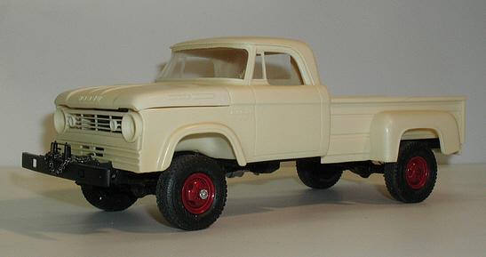
1964 Dodge D100
Chariots of Fire replied to carnut's topic in WIP: Model Trucks: Pickups, Vans, SUVs, Light Commercial
I never did get one of the Modelhaus Dodges but I did a '66 version about 16 years ago. Made it out of a Ford cab. Looking forward to seeing how this one builds up.
-
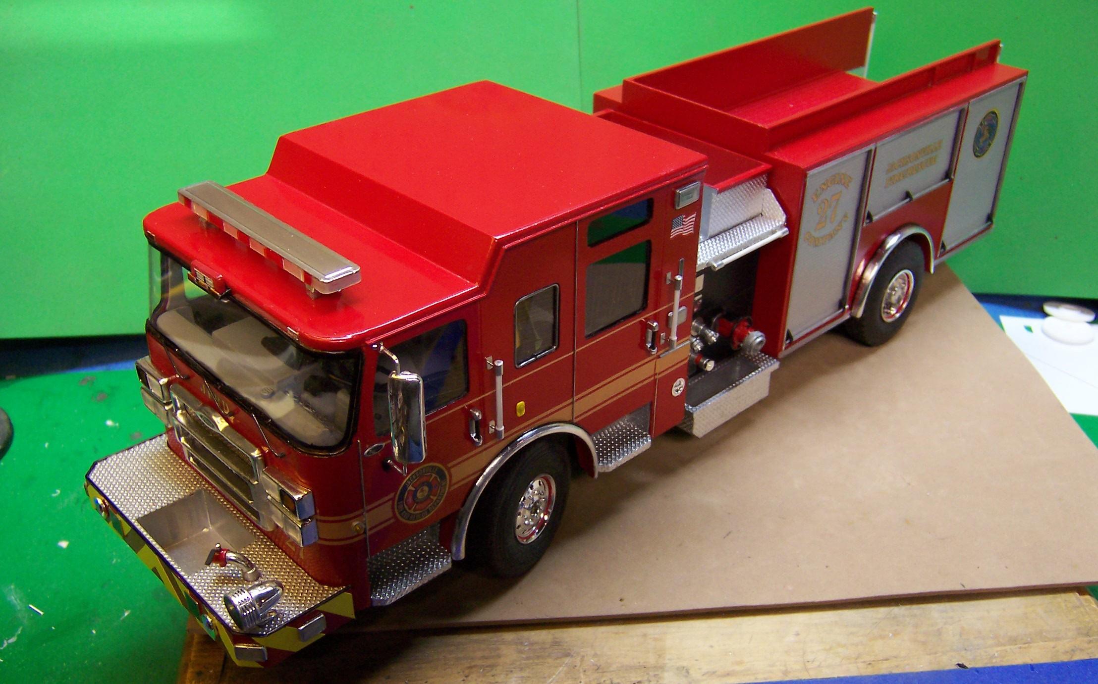
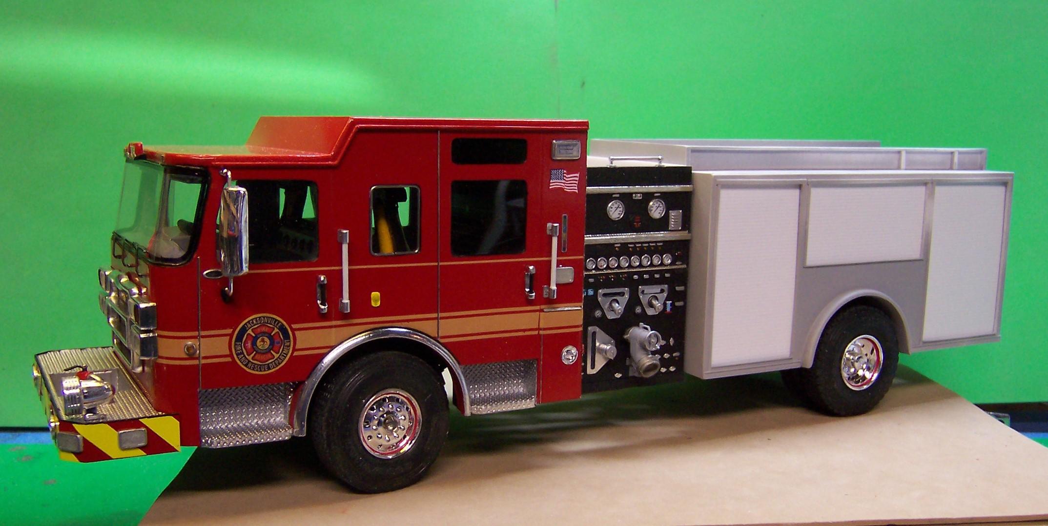
Just a couple of photos to show what it will look like with a pump panel in the middle. This came directly from the Trumpeter ALF so it is not the one that ultimately will be there but it gives the idea. I put a coat of primer on the body and it has had a first sanding. Another coat of primer and it may be ready for paint. The roll up doors will be done separately. Before I did the primer I took the time to thin down the rear wheel well surrounds. They were just too thick. I used a cutter in my Dremel and took better than 1/16" of thickness out of it. What a mess doing so! I never realized PVC was so fibrous on the inside. It is solid as a rock but the stuff went everywhere and stuck like glue! I had to get out the shop vac just to get it off my hands. Second time around I covered myself with plastic trash bags with holes cut out for my hands to stick through. When I finished the bags just went in the trash.? The Trumpeter kit has some nice detailing materials. That large diameter valve on the intake is direct from the kit. Nicely done. I did make the aluminum face plates for the two discharges above it and the one to the left. Otherwise it is the same as what came in the kit. The bright work is just BMF and a touch of a Molotow pen here and there. No two pump panels are the same so there are loads of possibilities to choose from.
-
RM Mack w snowblower....
Chariots of Fire replied to gotnitro?'s topic in WIP: Model Trucks: Big Rigs and Heavy Equipment
Lookin' pretty good, eh?? Like your auger work!