Chariots of Fire
-
Posts
2,781 -
Joined
-
Last visited
Content Type
Profiles
Forums
Events
Gallery
Everything posted by Chariots of Fire
-
 Thanks for your kind comments, guys. Now it's on to the next one! Whatever that might be!
 -
I guess the next show where it could be seen will be Classic Plastic. There is a small show mid July in Meriden, CT but it is mostly fire related diecast. I will need to arrange for the eventual owner to let me "borrow it" for Classic. Look forward to seeing you Neil!
-
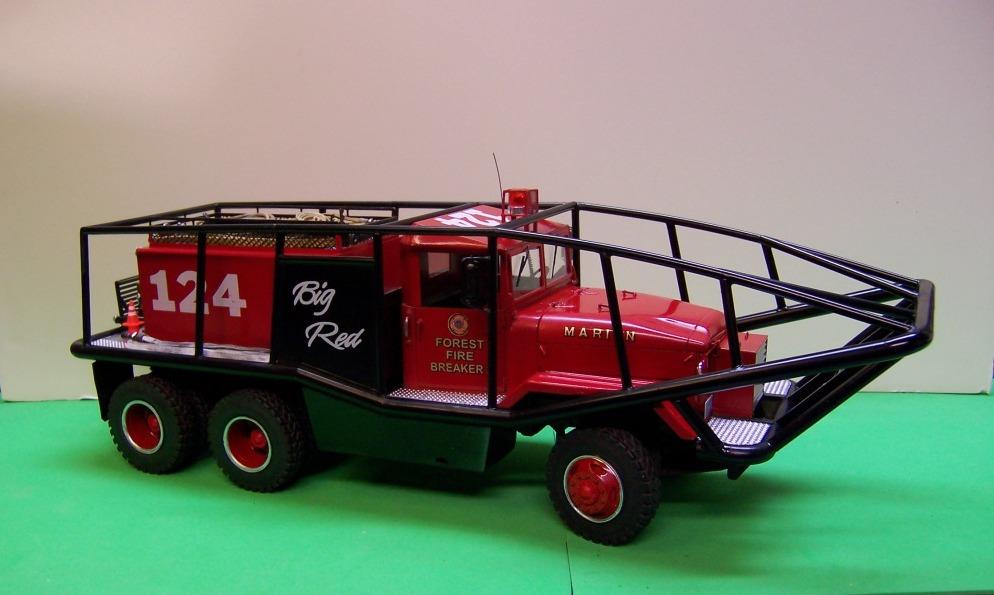
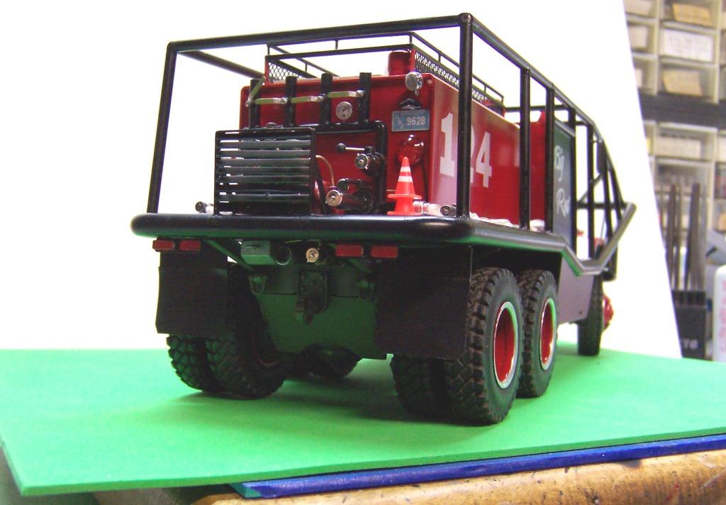
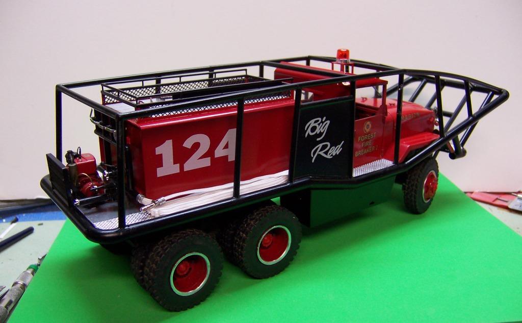
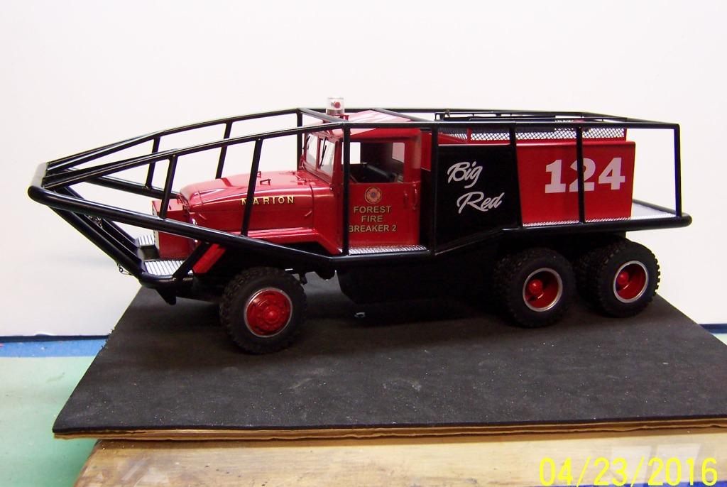
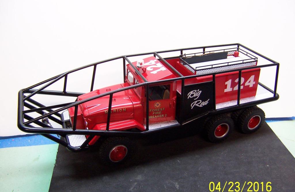
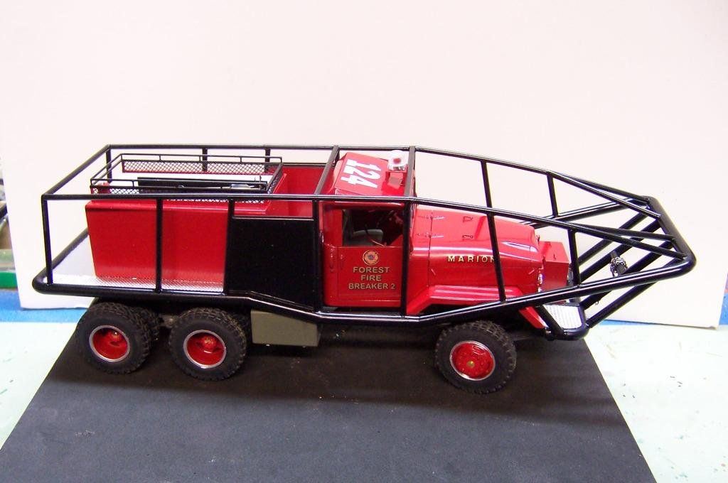
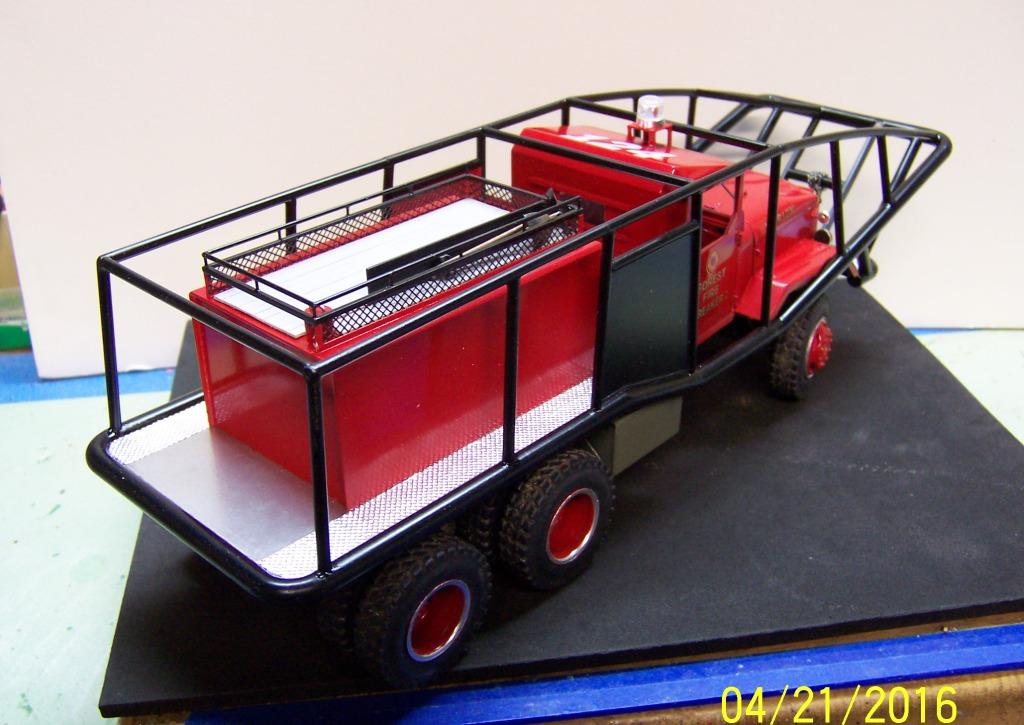
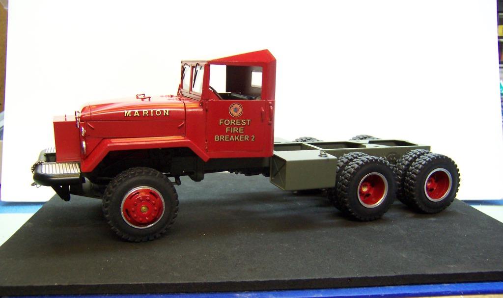
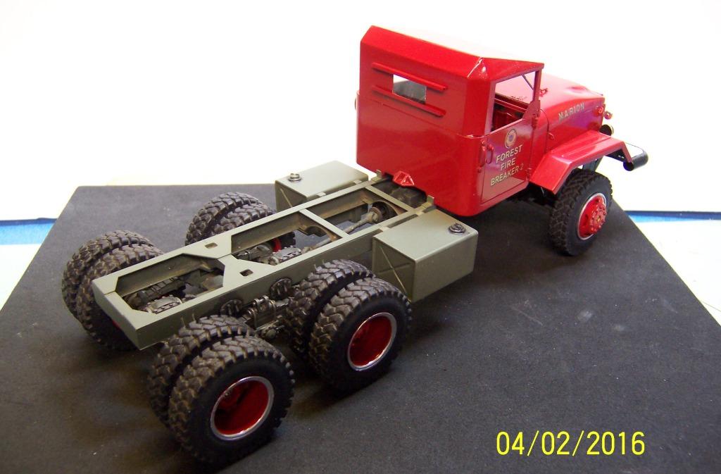
It's been quite a journey but the 1957 Diamond T M-52 Brush Truck is ready for delivery. The shops finished the last few details today that include the hose load, radio antenna, some cleanup and tweaking some things here and there. You can see the progress of construction on the Work in Progress section but now it's ready to display in full.

-
SSSHHHHH! Greg! Those elves are on loan from Zoli! Nobody is supposed to know!
-
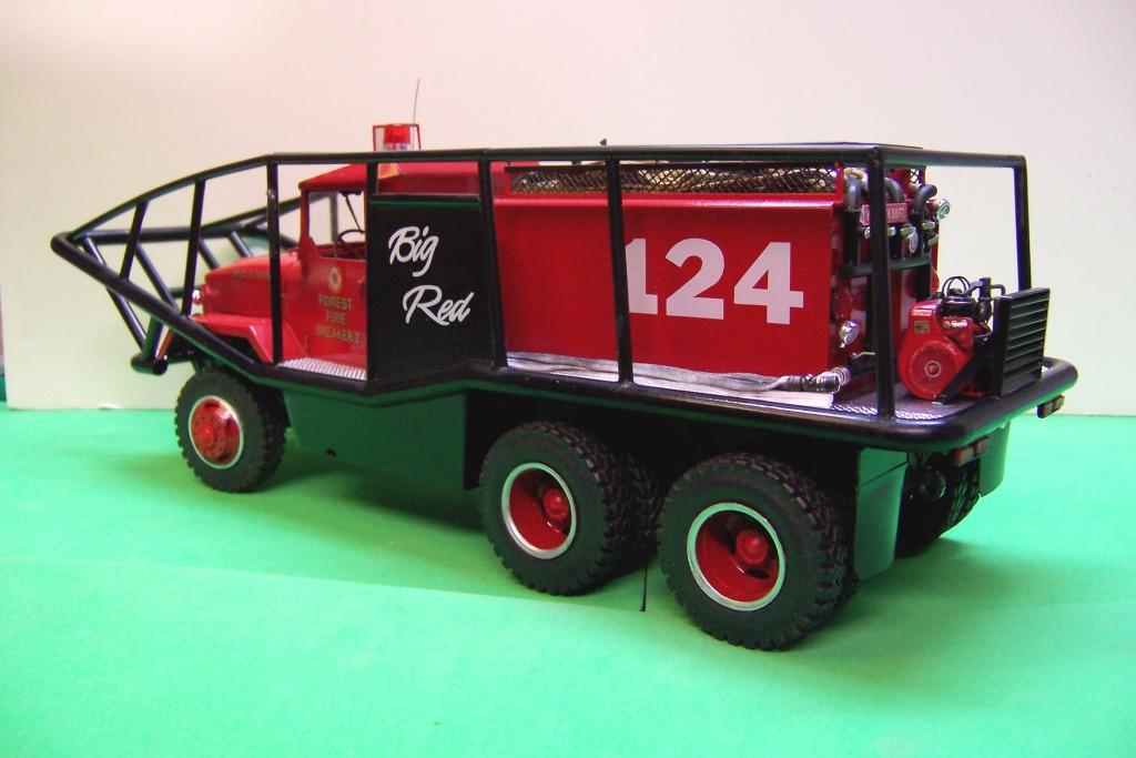
While awaiting some Plastruct 1/8" elbows to finish off the rear plumbing I turned attention to making up the siren for under the hood and the final details at the rear of the rig. With a couple of photos and some actual measurements a pattern was drawn out of the siren. Aluminum rod was turned to the appropriate dimensions. I used some photoetched HO scale rooftop walkway material to make up the outside perimeter. Not exactly like the prototype but the idea is there. A hole was drilled in the bottom to secure the photoetch with a pin. Another hole was drilled in the bottom of the motor base for a second mounting pin and a strip of aluminum was wrapped around for the mounting bracket. A little paint and the only thing lacking is that wailing sound. With the exception of finishing off the plumbing for the hoselines on the top the rear is now finished. Red flashers and spot lights, license plate, and pump engine switches and throttle were added. Under the hose body is the tank fill line and two lengths of hard suction, one of which has the strainer attached. Mud flaps were made with 0.020 plastic sheet stock and some black electrical tape stuck face to face. Some traffic cones were also added from the parts box. They actually carry some on the real rig.
-
Thank you, Dennis!
-
Sorry, Tom, it's called a "shrink machine". Got it from a guy who has elves working in his shop! As for the pump engine starting?? Well it won't until I install the switch and throttle..which I totally forgot until this moment! And thanks for the B-day wishes. I'm now approaching the age of dirt!
-
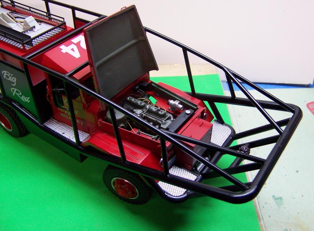
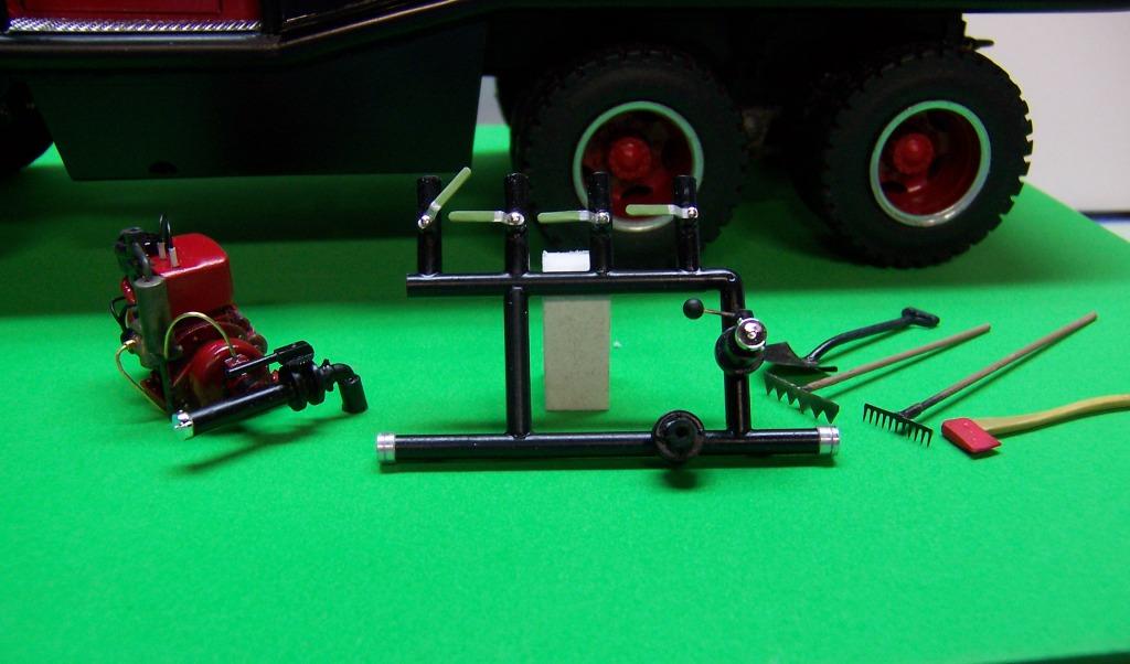
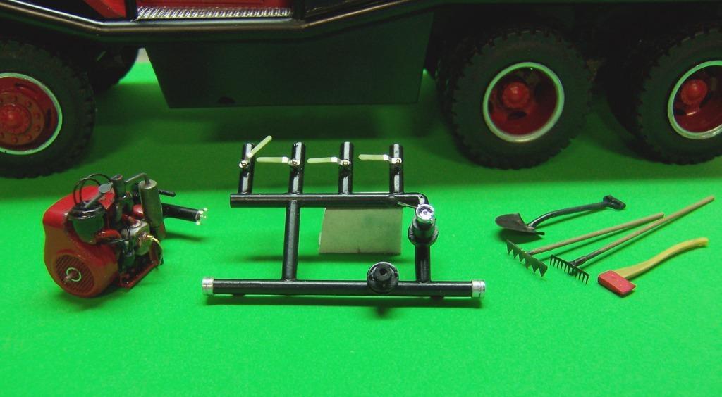
Thanks, Dennis. Once I had the basic measurements and some photos to go by it was just a matter of finding the right materials. I made the engine from a piece of plastic deck board material. Not sure of the correct name for it but it is very easy to sand and shape. The crankshaft housing and the portion where the plugs are is one piece. The face of the crank housing was routed out and then a small piece of brass screen was put over the opening along with a trim ring. The plugs are pieces of small brass tubing. The rest is bits and pieces from the parts box, plastic tubing and brass wire. The pump was made from one half of a turbo from a KW kit. The plumbing is plastic tubing.
-
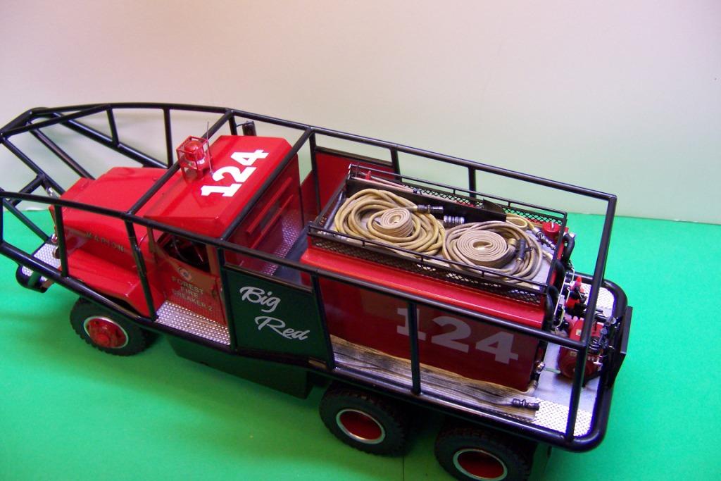
IT's been a few days since the last post. Had some non-modeling chores and other stuff to take care of. And I needed to get back to the fire house to measure up the pump and plumbing for the back of the rig. Got that done about 10 days ago. After a bit of study of the pictures and a search on line I found that the pump engine was a 2 cylinder Wisconsin. The pump is a Hale centrifugal. So here are some pics of the pump and plumbing prior to installation and before adding some gages. I need also to add some valves to the bottom discharge lines. The pump and manifold are now installed and the first hose line has been laid in place. This is a hand line that would not normally be pulled while in brushbreaking operations. But not every incident requires that and sometimes the truck will be standing still while wetdown is in progress. So they would pull this line and do the final extinguishment.
-
Nice scratch building! Nice combination of cab and body.
-
Fun working with old stuff, eh! Just my kind of building!
-
Lowboy load
Chariots of Fire replied to signguy2108's topic in WIP: Model Trucks: Big Rigs and Heavy Equipment
Never thought to look in that kind of store for goodies! I will now! -
It's fun doing that type of thing. Great job! Some things look a bit oversize for a D6 but the effect is there. Should look pretty nice on a lowbed.
-
Frustrations!
Chariots of Fire replied to Jim B's topic in General Automotive Talk (Trucks and Cars)
So what made it fall apart?? -
Michael: If you go to CapeCodFD.com you will find a section on these types of trucks and how they are used. It's a great website for all kinds of things that make up the Cape Cod fire services.
-
Shops continue to be busy zeroing in on the last of the major building. One more trip to the fire station is in order to get information on the pump and plumbing for the rear behind the tank. The side protection was added today along with a few decals. The end caps were added to each of the wheels so hopefully they will not need to come off again!
-
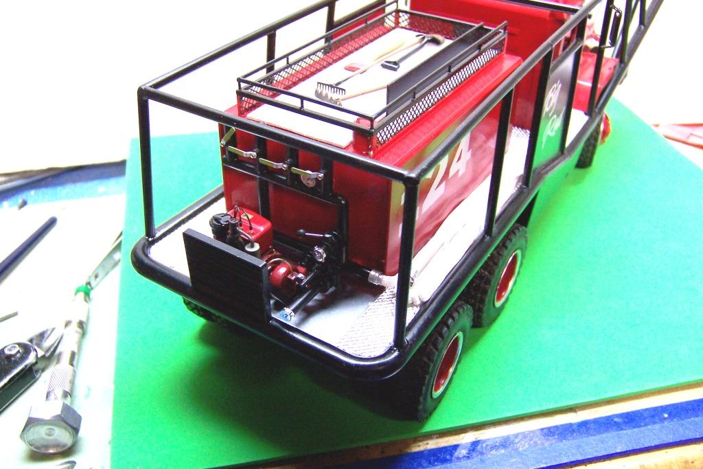
Some more progress since getting back from NNL EAst. The brush bars are done and the tank and new hose bin on the top have been finished. Got some hand tools done up with more to come along with some forestry hose and larger filler hose to put in the bin. Next up will be to finish the side protection for the fuel tanks and then move on to the pump and plumbing for the rear. We're gettin' there!
-
You are welcome, Tom. Too bad we didn't meet! Would have enjoyed talking with you.
-
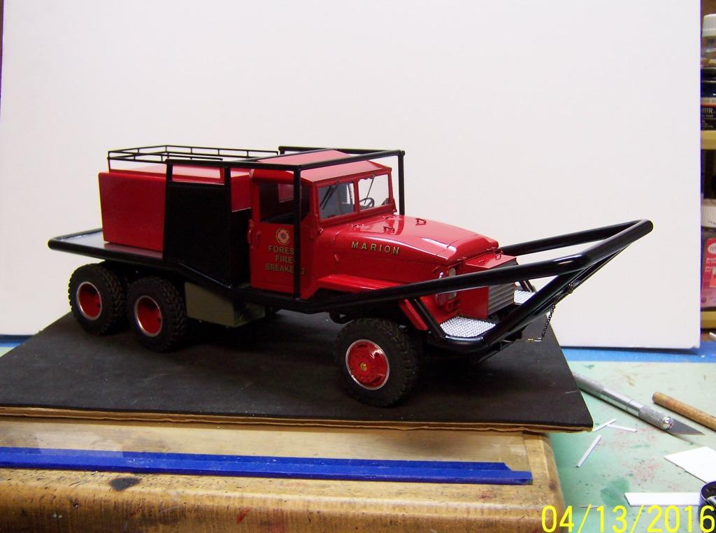
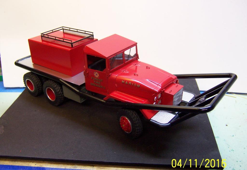
Here is some more progress with the side protection partially completed. There will be more bars that will run from those at the front of the cab to the upper bar that is out front. There is also added bar work that extends toward the rear. I re built the hose basket on top of the tank but have not added the mesh sides yet. Glue and paint have to dry some and I need to finish re painting the tank. After that the fuel tank protection and sides under the cab doors will be done.
-
After a short layoff on building we were back at it again. Had to get several more measurements in order to begin the bar work around the truck. If that front bar looks high and way out front that is how it is on the real truck. Too much IMHO but that's the way it is. Water tank is done but I messed up on the hose bin up top and will have to do it over. It should have gone all the way to the back end of the tank! Should have studied my pics a little more!
-
Mack R895 RSX
Chariots of Fire replied to Superpeterbilt's topic in WIP: Model Trucks: Big Rigs and Heavy Equipment
That is one beast of a truck! Great start. Will be following this along! -
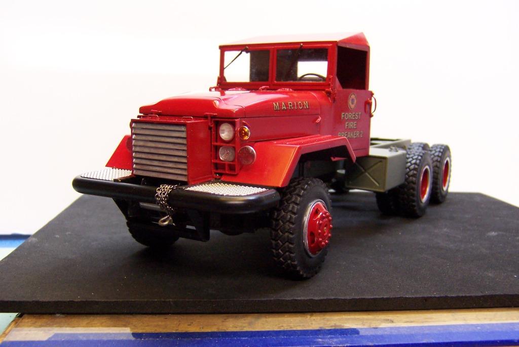
The fuel tanks have been added behind the cab and a lead chain and hook were added to the winch cable.
-
The winch cable is bead wire I found at Michael's craft store. It's real springy so when you wrap it on the spool you have to keep it tight and then superglue it in place. It does have a realistic look to it. Better than just plain wire or thread.
-
One or two trips in the woods on a good hot fire and that paint won't shine anymore. But fire departments do like to keep their rigs looking nice.
-
Got the shops in full gear today. Finally got the hood sides completed and a bit more wiring under the hood. The front bumper is in place along with some skid plates under the front. Directional lights have been added and the doors and hood have been lettered. Still to be added are the small centers to the hub of each wheel. Those brass screws that hold the wheels on will be covered.