Anglia105E
-
Posts
3,487 -
Joined
-
Last visited
Content Type
Profiles
Forums
Events
Gallery
Everything posted by Anglia105E
-
Pleased to hear that you like this one Len . . . As regards the gas tank, there has been a slight change of plan, which is detailed in my next post . . . David
-
Thanks Brian . . . This 1:24 scale build is getting the kind of attention that I gave to the 1:16 scale Rolls-Royce build . . . David
-
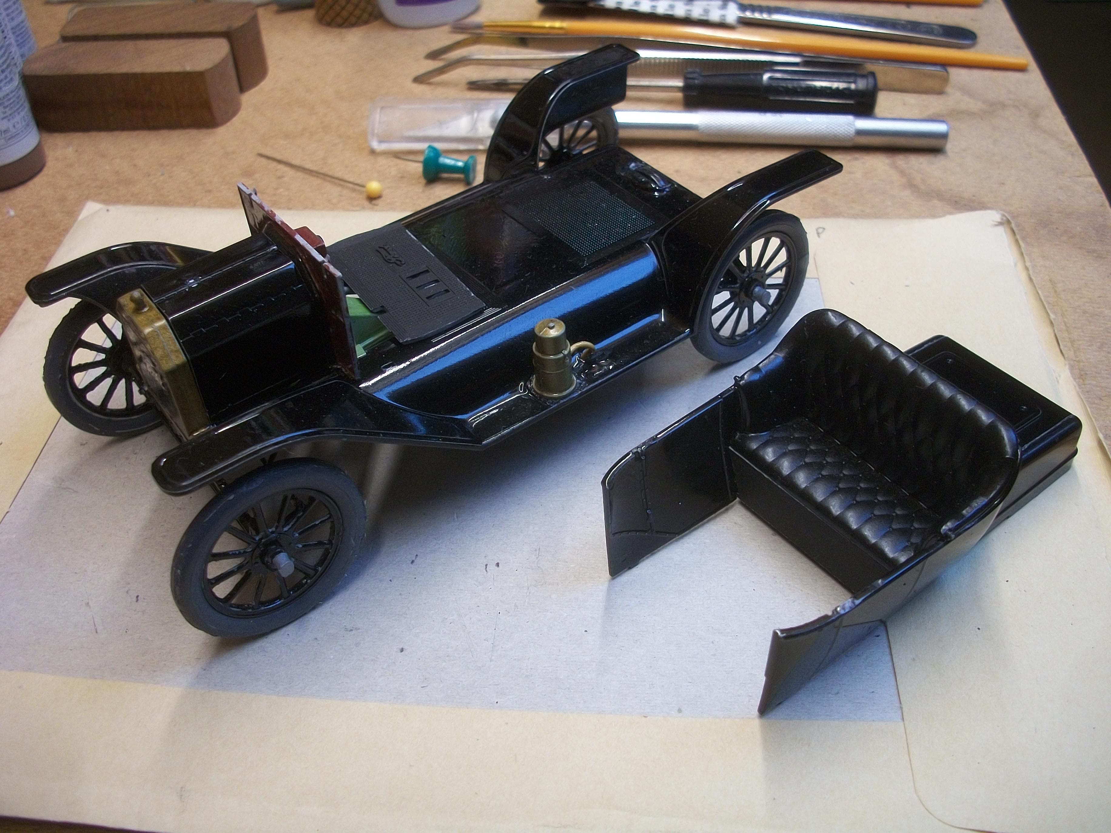
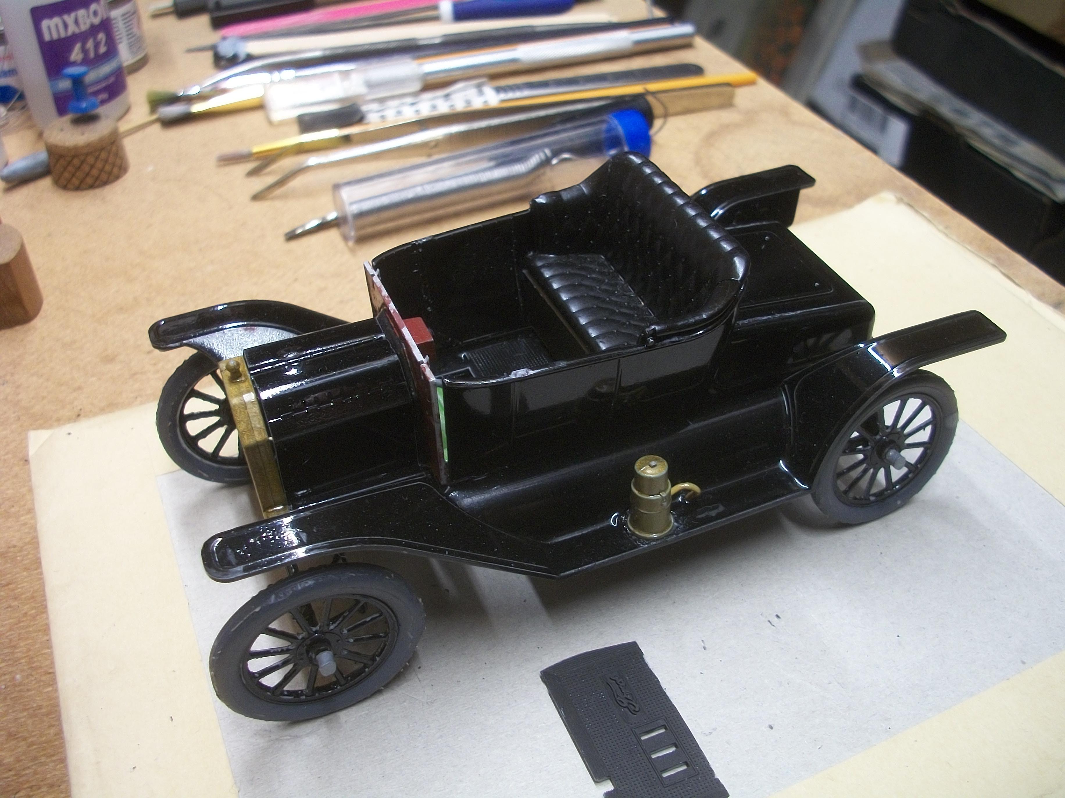
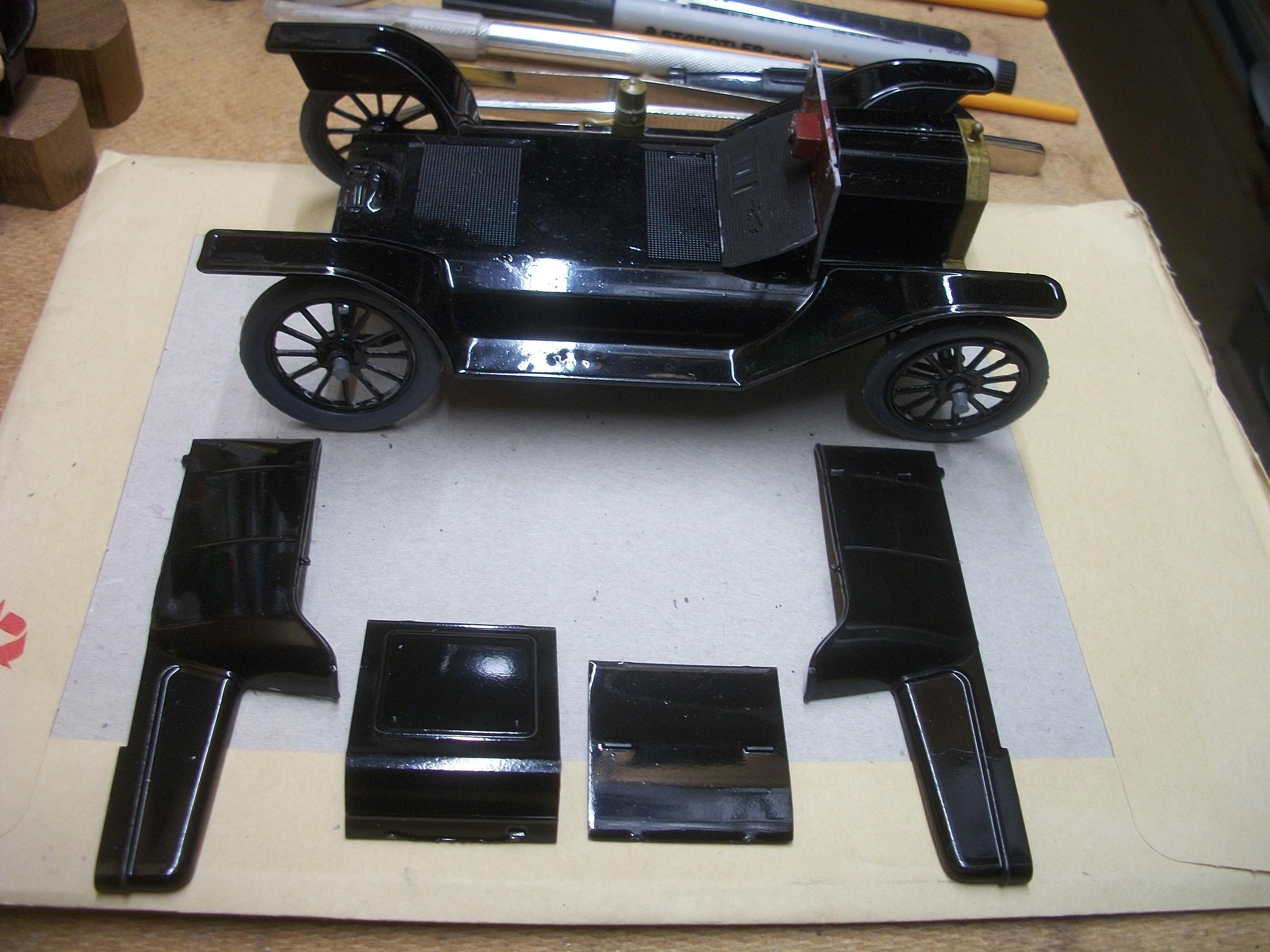
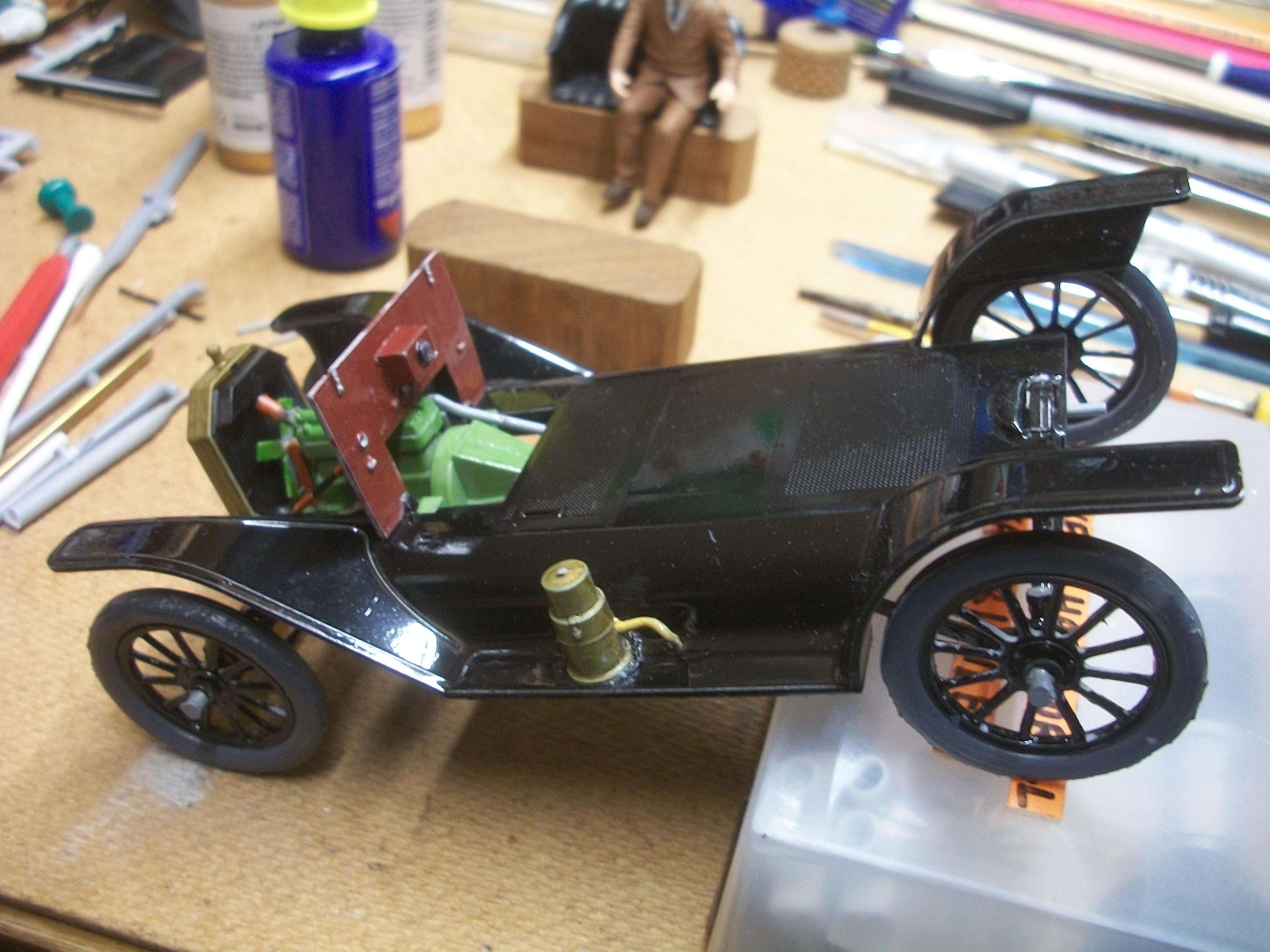
Assembling the four body panels was actually very tricky . . . Part of the problem was of course my 71 year old fingers fumbling with the parts. I had already cleared the joining edges of the body panels, so that there were no traces of the black paint. Once Revell styrene glue had been applied to those clean edges, I carefully and precisely positioned the adjoining panels . . . Holding them steady while the glue took hold was quite a challenge for me. Anyway, the parts all went together reasonably well, and the following photos show the upper body being test fitted to the lower body assembly . . . The next part to be fitted into the upper body was the seat support panel, which slotted in nicely and was glued in place. As I was test fitting the seat onto the seat support panel I found that the overall fit of the seat within the body was so good that no glue would be required. This led me to an interesting idea . . . Maybe I could fabricate / scratch build a petrol tank / gas tank to fit under the seat, as on the real car? So, the plan now is to make a gas tank from an empty plastic solder container, then glue a circular disc of thin white card to the open end of the container, paint the tank in aluminium enamel and glue the tank inside the under seat space . . .The seat can be placed on top of the tank, with no glue needed, allowing the tank to be viewed easily. A filler cap can also be added to reproduce the tank accurately. David

-
Thanks a lot Andy . . . Yes, I am quite pleased with the progress so far on this build. This is turning out to be a really interesting model car. We have heavy snow and sub-zero temperatures here in England at the moment, for at least a few days until the weekend . . . David
-
Thank you David G., and I do like to think of it as model engineering . . . Sometimes I get things right, but not always ! David W.
-
Thanks Carl . . . Your comments are always appreciated. David
-
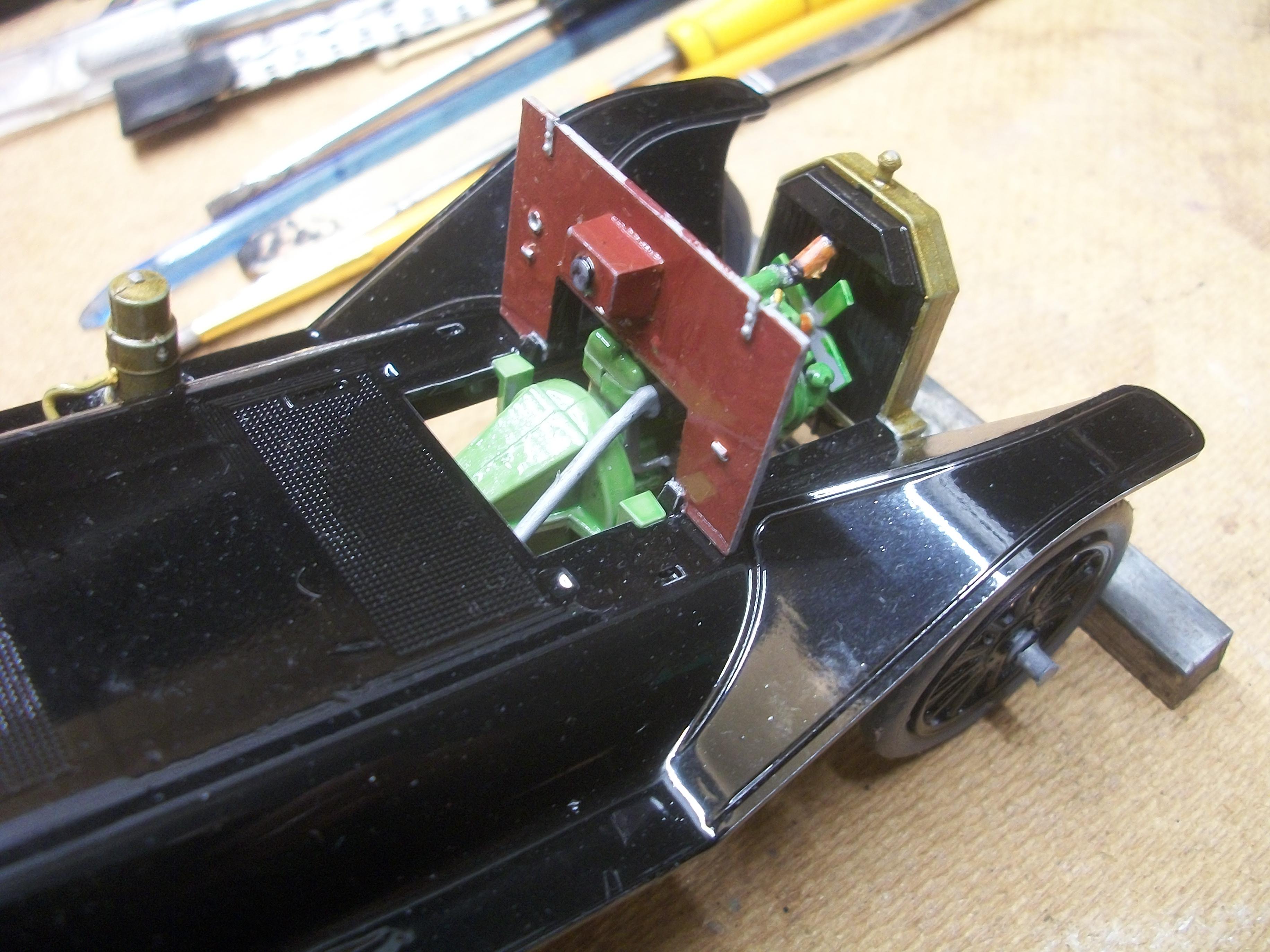
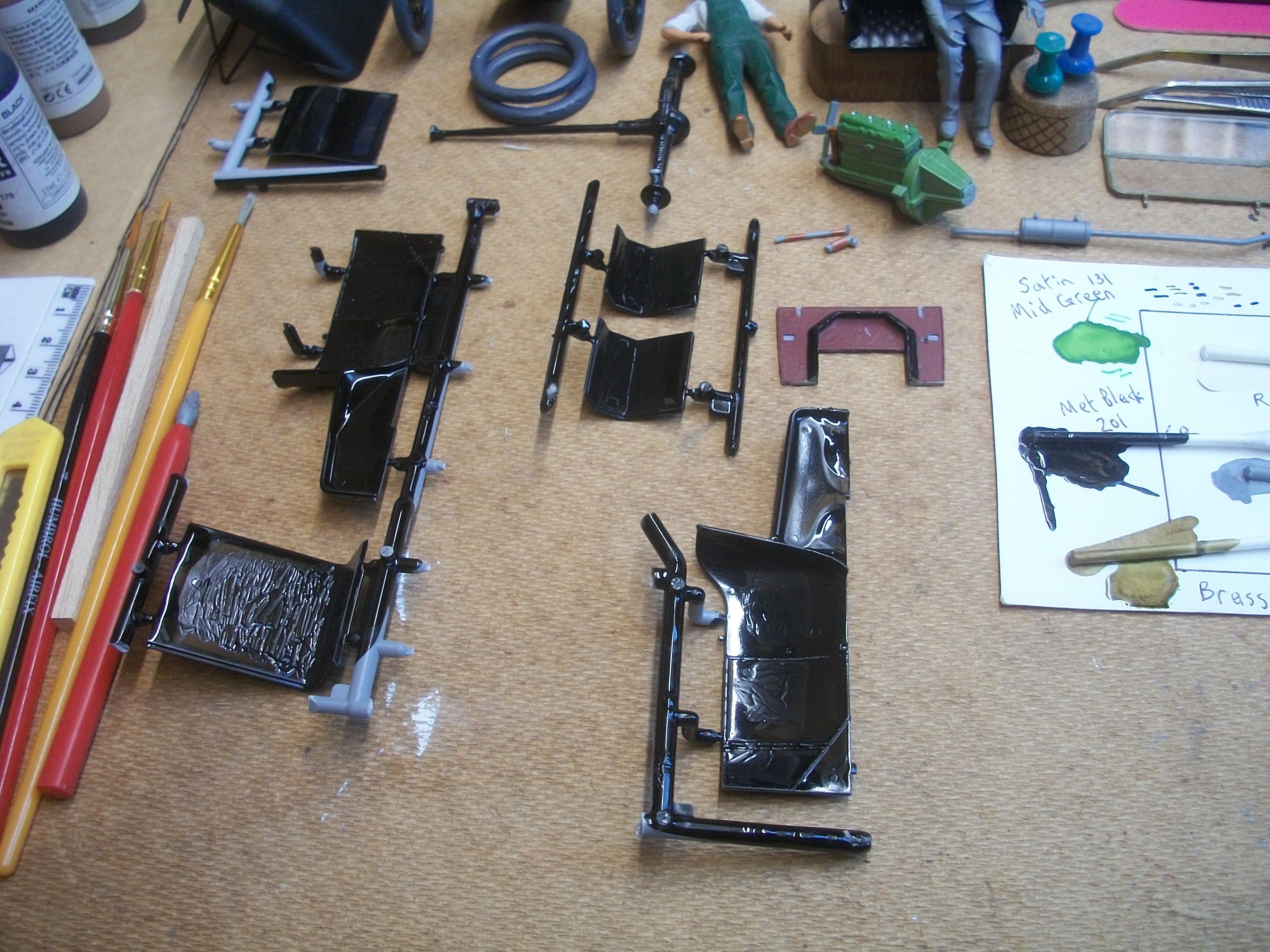
The assembled firewall has now been glued in place, and also the support bar between the firewall and the radiator shell is glued in place. This support bar will have the two bonnet / hood panels attached to it at some point . . . One of the four spark plug leads is waiting to be glued to the top left, second row down white porcelain pin, having already been attached to the No.1 spark plug . . . The floor panel is resting on it's mounting points, and almost ready for fitting. I have prepared the four body panels that you see in the following photos, by scraping the excess black paint from the joining edges, and then test fitting these panels. They are the trunk, the seat back and the two body sides . . . David
-
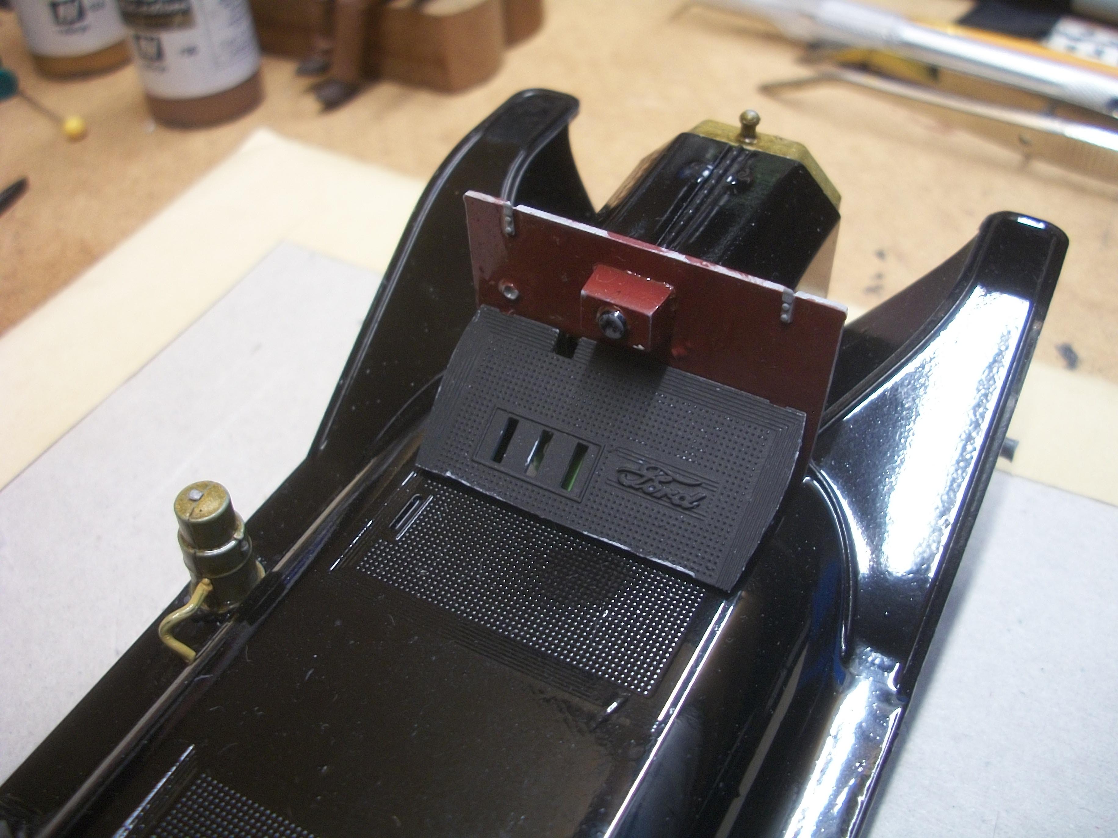
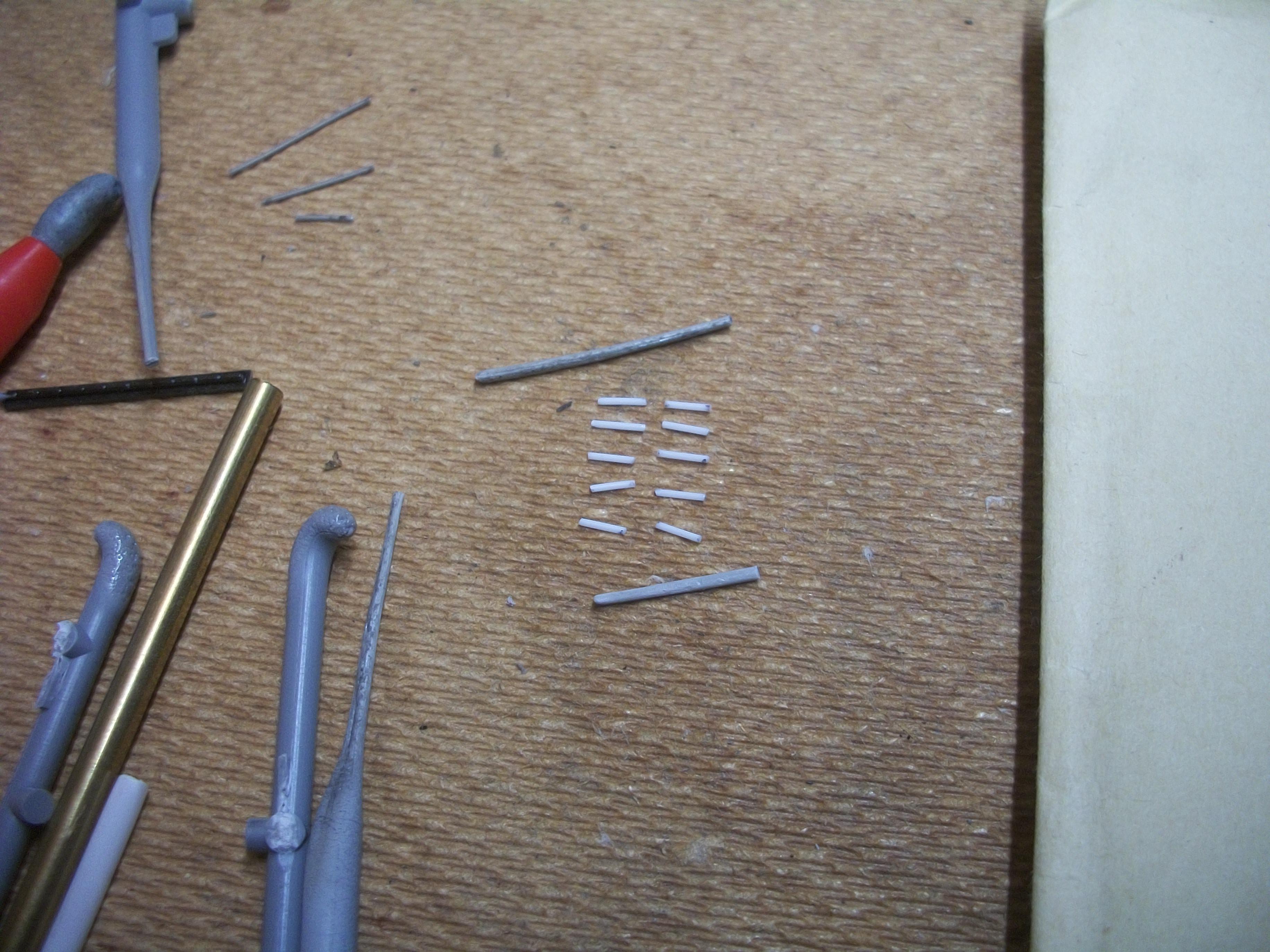
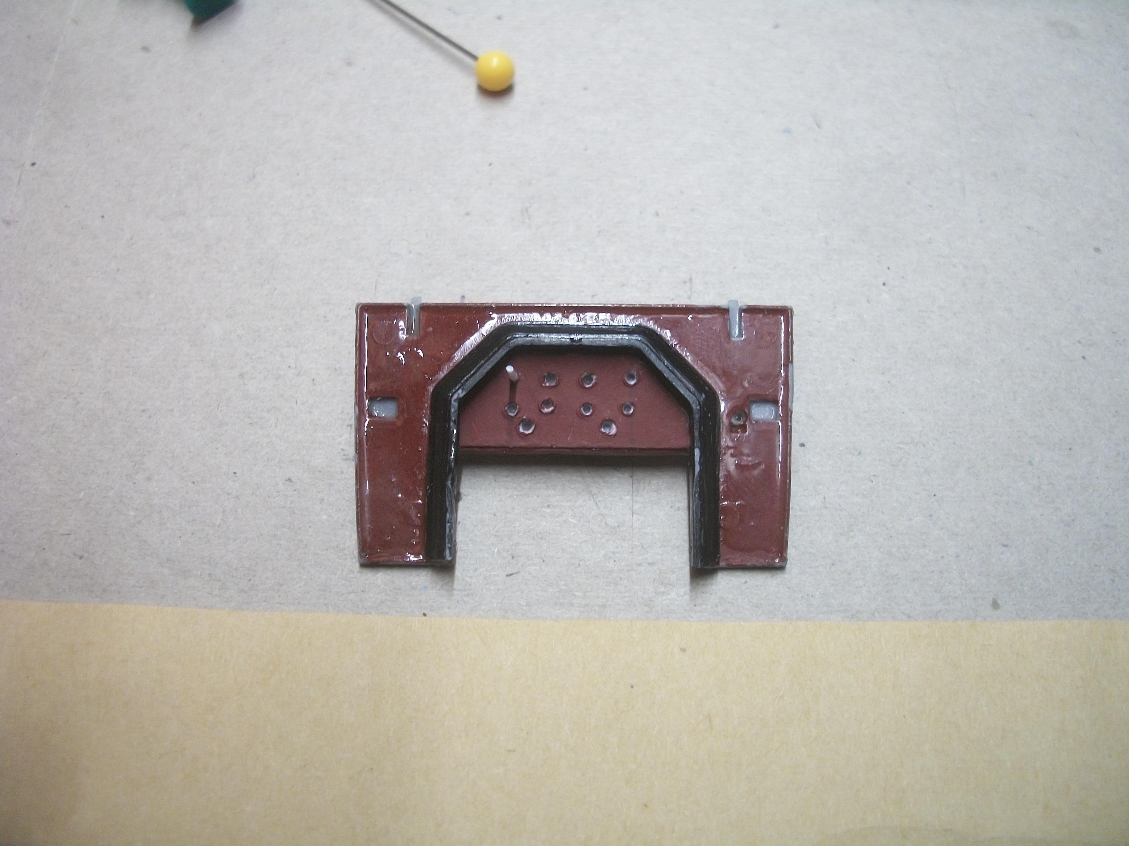
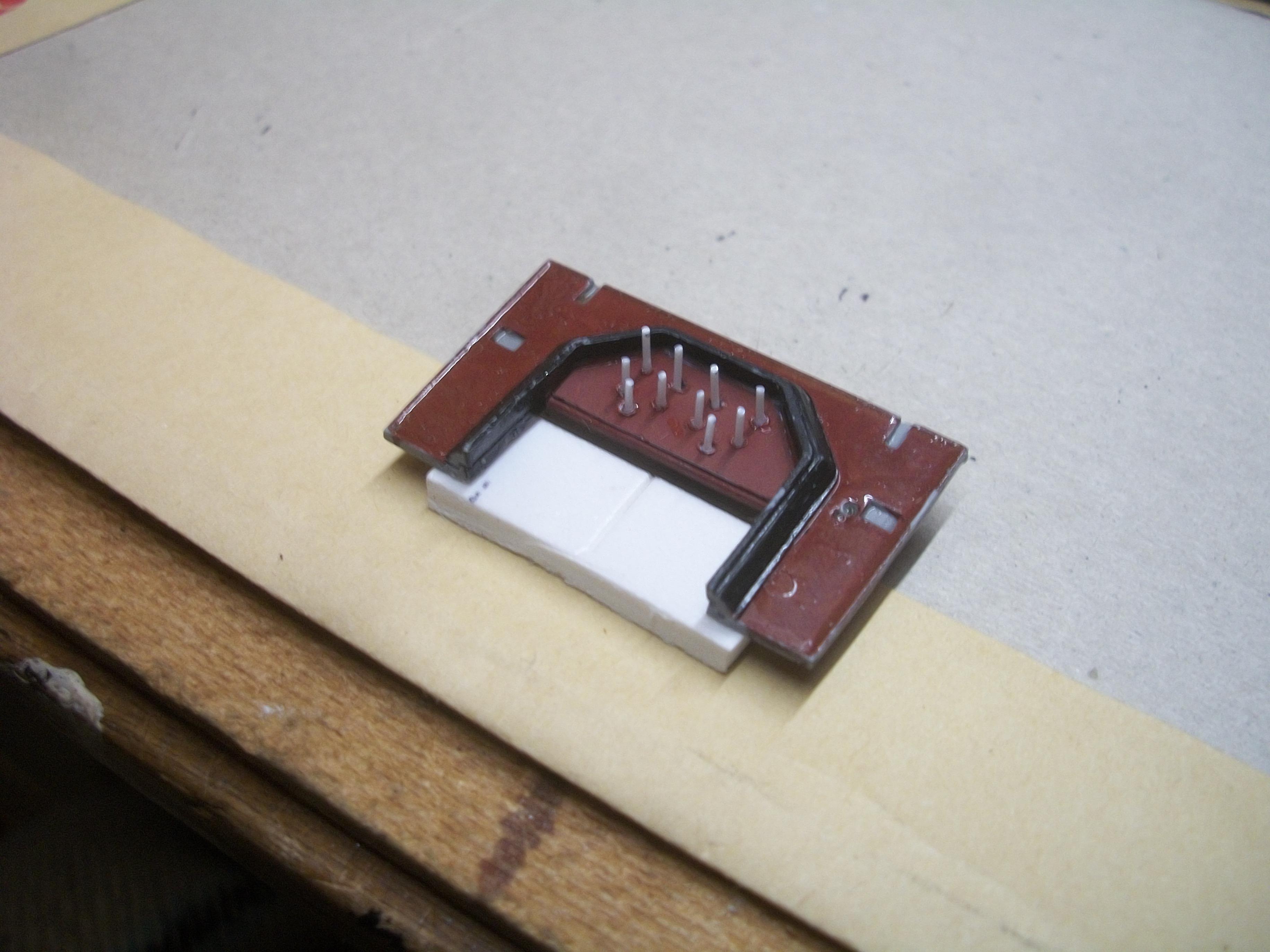
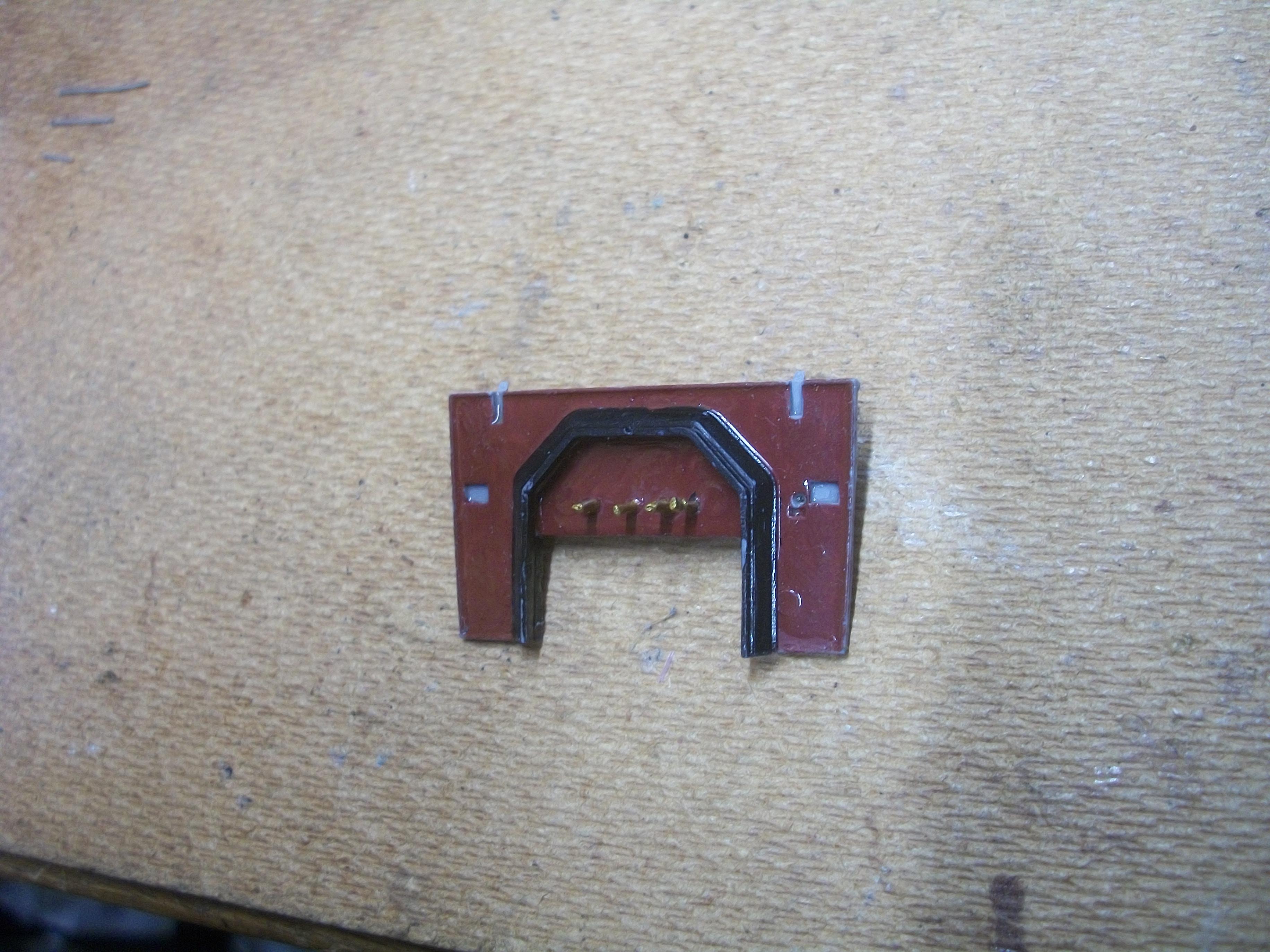
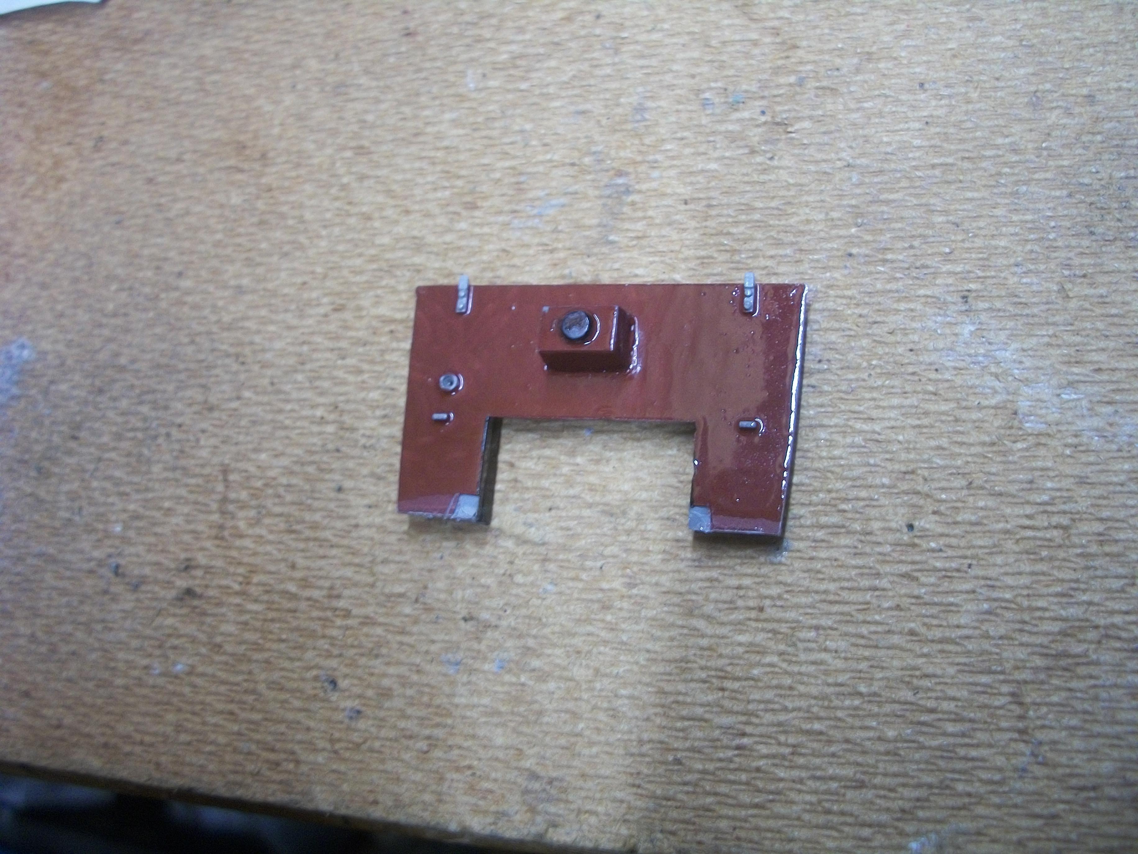
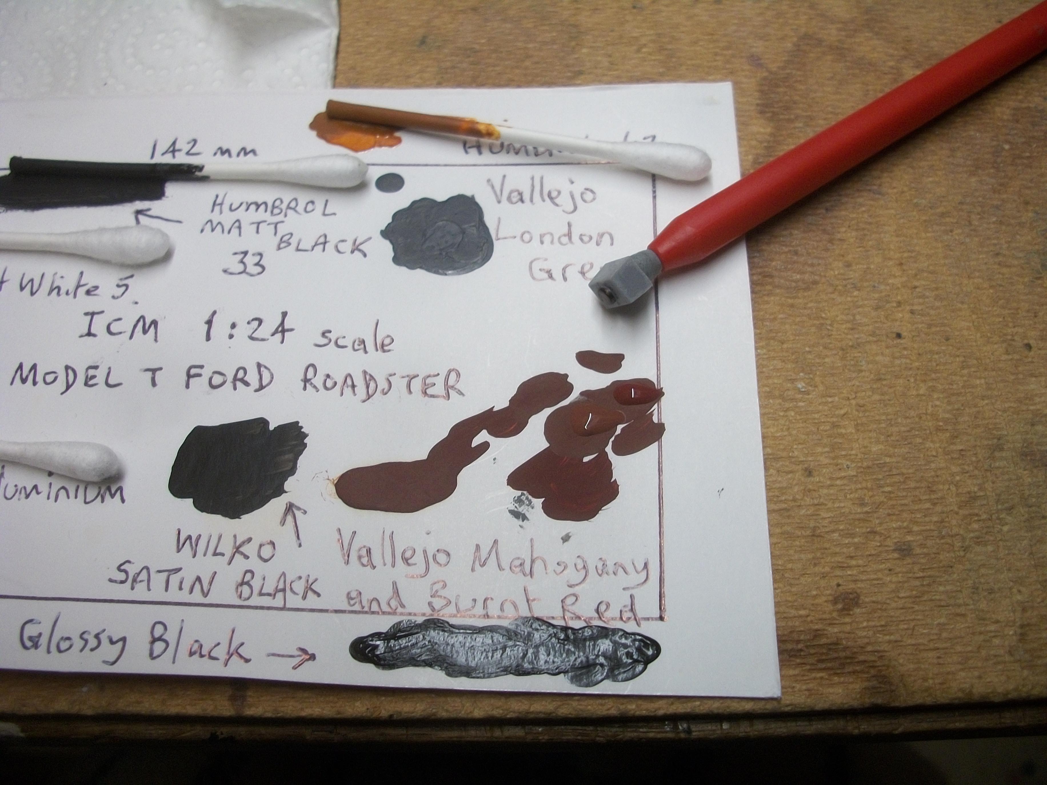
First of all, I cut out a piece of thin white card that fitted precisely into the frame of the firewall, and this was PVA glued to the firewall panel . . . Then I painted the white card with the Vallejo Mahogany Brown and Burnt Red mix, to simulate the cherry wood colour. Next step was to cut ten 3 mm lengths of the Evergreen 0.025 inch styrene rod, so that I had 10 white porcelain pins . . . Using a dress pin, the one in the photo with a yellow top, I made ten holes in the card, and then used a push pin with the green top, to enlarge the holes slightly . . . My thinking was to insert each of the ten white styrene pins into the holes of the card, and then the super glue would fix the ends of the pins to the styrene firewall part itself. This procedure seems to have worked quite well. All ten white porcelain pins are in place and setting overnight . . . The four spark plug leads will be attached to the second row of pins down from the top . . . David
-
In the first place, I cannot understand why these parts have to fall to the floor . . . Almost on a daily basis, small kit parts leave my fingers and head off downwards to oblivion. Then, despite an extremely thorough search, usually on my hands and knees ( not easy at 71 ), using a good hand held lamp and staring desperately at every single square inch of the hard wood floor . . . Nothing . . . Absolutely no sign of the elusive missing part. The part has seemingly gone forever . . . Unless as you say, the part mysteriously and mockingly, suddenly appears within easy view later ! David W.
-
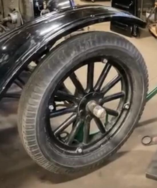
Thanks very much Mark . . . I can see from your excellent reference photos how these pins must be white porcelain. Already, I have decided last night to remove my first attempt at those pins, and re-do them in a different material, so this will be my opportunity to colour them in white as you suggest . . . Of course, I do want the detail for this Model T Ford build to be as accurate as possible, so your expert knowledge has helped me at just the right time ! Thank you again Mark . . . David
-
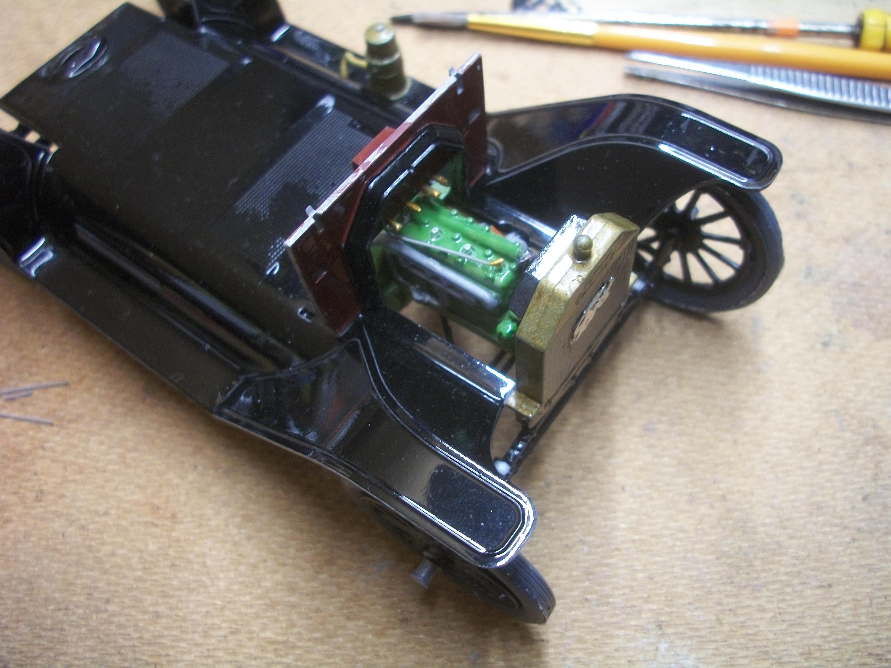
All four pins have been super glued to the firewall, and these have been painted Vallejo Brass acrylic. One spark plug lead has been glued in place to spark plug No.1 and the terminals have been painted brass also. The firewall has now been lowered onto the lower body floor and glued to the mountings. Next up, following overnight setting, there will be three more spark plug leads added, and all four leads will be glued to the pins on the firewall. Once the bracing strut that goes between the radiator shell and the firewall has been glued in position, I shall move on to the body parts assembly. David
-
I do understand your concerns regarding the fumes and the open flame, and it's not something that I do very often . . . More progress below . . . David W.
-
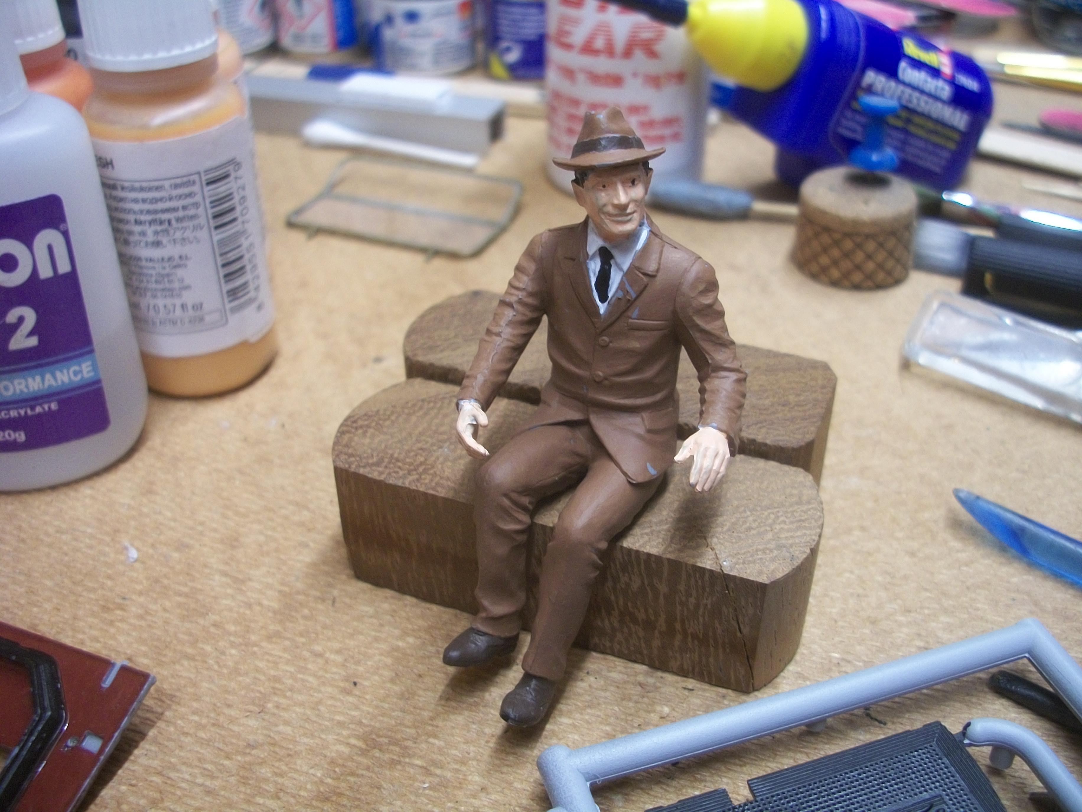
Further progress with the driver figure painting today . . . Vallejo Burnt Umber acrylic for his shoes and the hat band, then Vallejo Black for his tie, hair and eye pupils. The eye pupils need detailing for added realism. Two floor panels have been coated with the same Vallejo Black acrylic . . . I like to use different shades of black, by using different paint products. My local model builder friend previously showed me a technique that involves stretching a piece of kit sprue over a hot flame, and this produces a thin strand of styrene. I am cutting four short lengths of this stretched sprue to 3 mm and these tiny pins are being super glued to the firewall on the engine side. Once the pins are painted in brass, the four spark plug leads can be attached to the pins and the spark plug terminals with tiny connectors . . . As you can see from the following photos, the Vallejo beige brown acrylic paint finish is easily damaged, just by handling the figure while painting, so these areas need to be touched up in due course . . . David
-
The blu blob that the figure is standing on is Blu-Tack, which I have on a piece of wood for supporting parts that I cannot hold in other ways. Yes, I suppose this driver figure does kind of resemble Henry in a way ! Here are two photos showing how another model builder has done the spark plug leads very nicely I think . . . David W.
-
Thanks Carl . . . I am quite pleased with my recent steady progress. David
-
Following an overnight drying period of more than 24 hours, the yacht varnish that I have applied to the firewall is still slightly tacky. While I am waiting for the firewall varnish to be fully cured before handling the part, I have done some figure painting today . . . The driver figure for the Model T now has a single coat of Vallejo Basic Skin Tone acrylic for his hands and face. Also, he has a white shirt, brown suit and hat. I need to drill some tiny holes in the firewall for the spark plug leads and mount the firewall on the lower body floor, behind the engine. David
-
I couldn't have put it better myself David . . . Certainly I begin to feel differently about this build, now that all four wheels are on the ground. From this point onwards it feels as though I am working on a real car, and I can visualise each process more precisely . . . David W.
-
Thanks Brian . . . The problem solving is all part of the scale model car building process for me. I shall probably add some spark plug leads from the top of the engine back to the firewall and the coils box . . . David
-
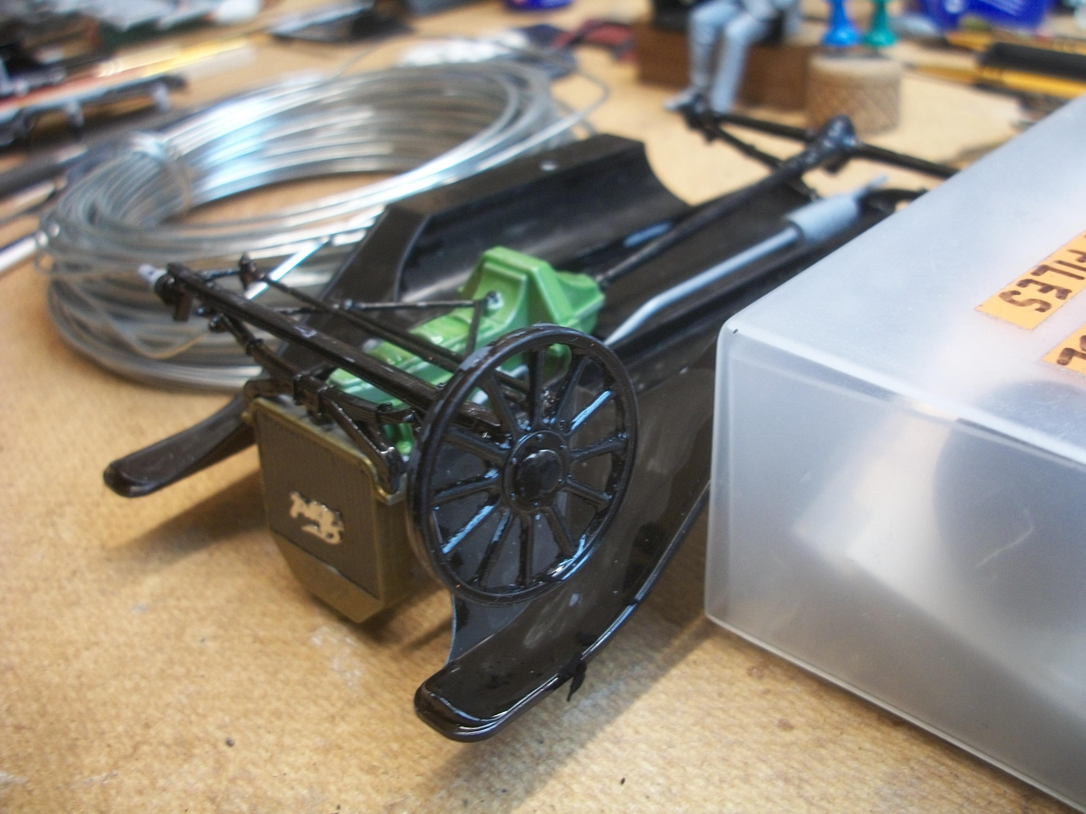
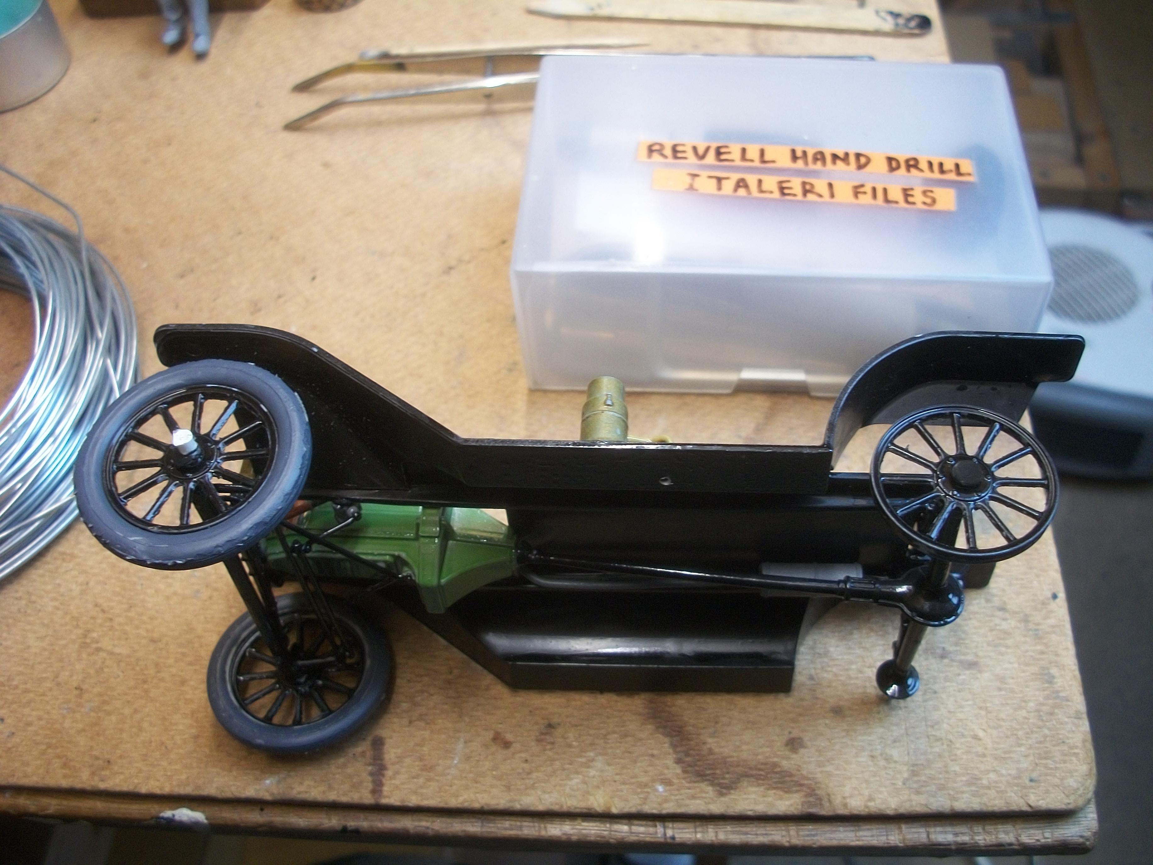
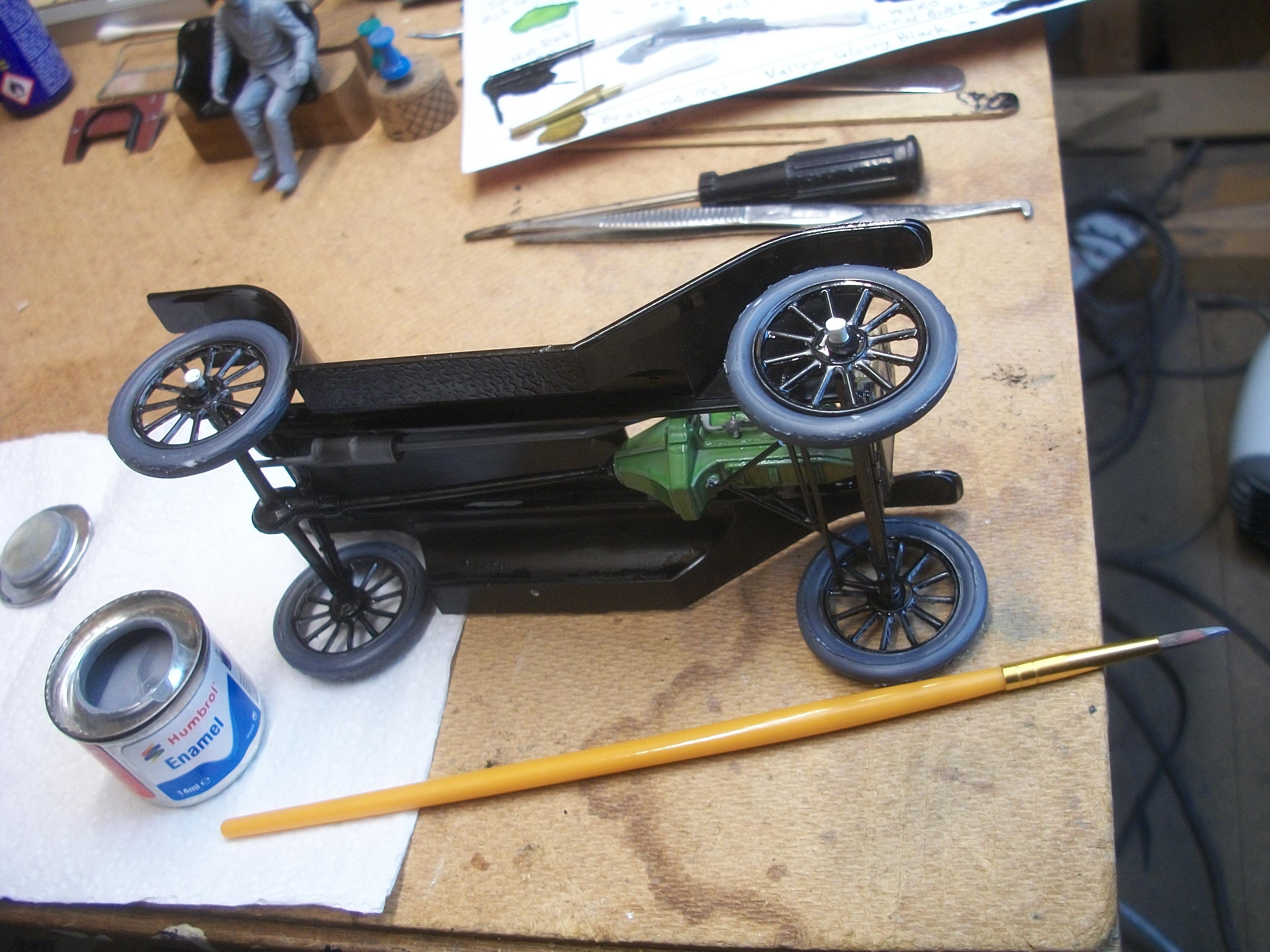
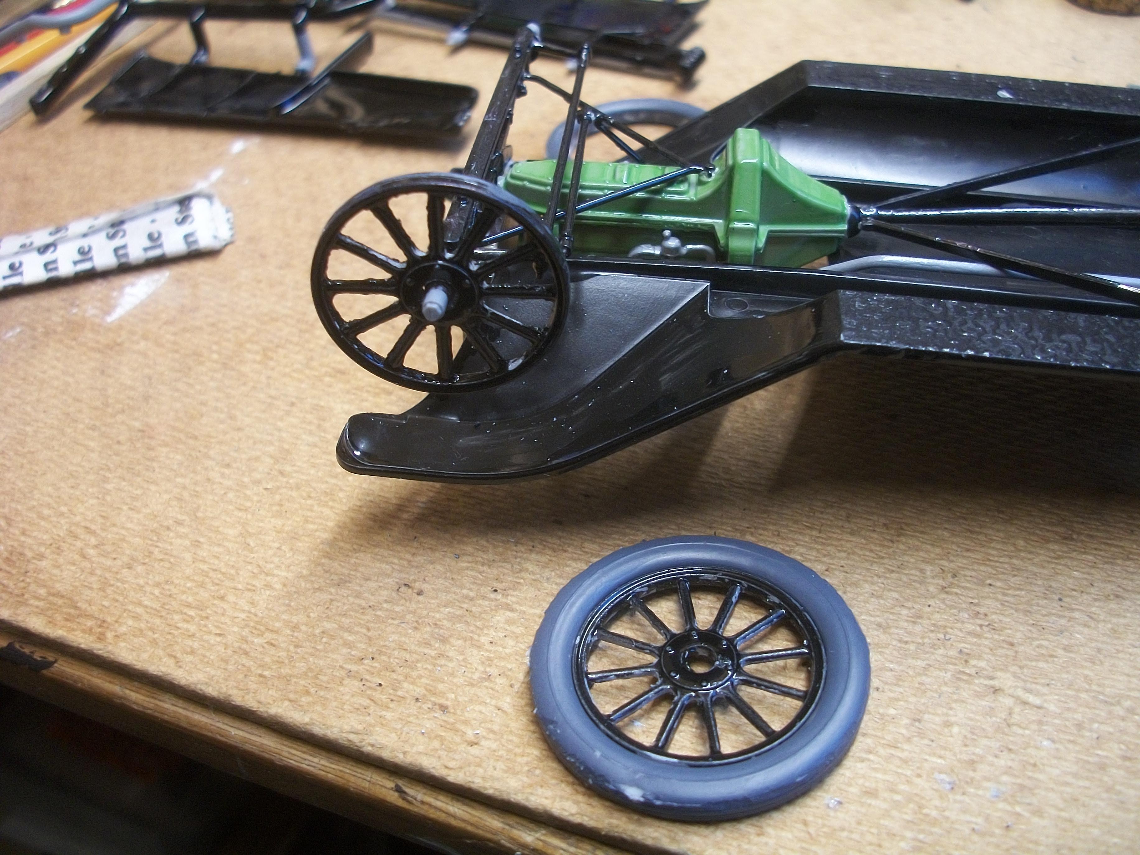
The red rubber tubing became split and broken too easily, and I believe this is because the tubing is from the 40 years old Gunze Sangyo kit. I gave the matter some thought over the next 24 hours, and a better method occurred to me . . . By heating the tip of a flat blade screwdriver in a tea light flame, I set about melting and flattening the outer hub of each stub axle. Having used the hot screwdriver technique with the Phantom III door hinges, I was confident that this approach would work . . . Sure enough, the wheel when fitted over the inner hub was free to rotate, while at the same time the wheel could not come off the axle. Now that each outer hub was melted into a flat disc, all I needed to do was fabricate four pieces of 3mm material from cotton bud stalks and super glue them onto the hubs . . . These new outer hubs have been given a coat of Humbrol 56 Metallic Aluminium enamel to finish off . . . We have a rolling chassis, and the ' car ' stands level on the workbench surface. David
-
Just approaching midnight here in England, so I shall be posting in more detail during tomorrow (Saturday), but I have discarded the idea of using the red rubber tubing and instead I have come up with a much more satisfactory method . . . All will be revealed in due course ! The material used actually represents the outer hub cap, and this will be painted aluminium, so not blackened . . . see photo below. David W.
-
Working on the passenger side front hub, I have managed to slide the wheel all the way onto the hub itself, and also enabled the wheel to rotate. While I was looking for a way to secure the wheel, I found a short length of red rubber tubing which was left over from the 1:16 scale Gunze Sangyo Rolls-Royce Phantom III build . . . My idea is to place the tubing tightly over the outer hub of the front axle, which will prevent the wheel from coming off the hub, while at the same time allowing the wheel to rotate freely. The rubber tubing can be cut off at around 3 mm once the wheel is secured, and all four hubs on the front and rear axles can be dealt with using the same method . . . Once the pieces of tubing are in place they can be painted with aluminium enamel, and they should only appear to be slightly larger in diameter than the original hubs themselves. David
-
Yes David I would say this can be described as an easy build, and if the build does take all of November to complete, it will simply be that I am taking my time and adding detail where I can . . . Certainly engaging and I am really enjoying this one . . . David W.
-
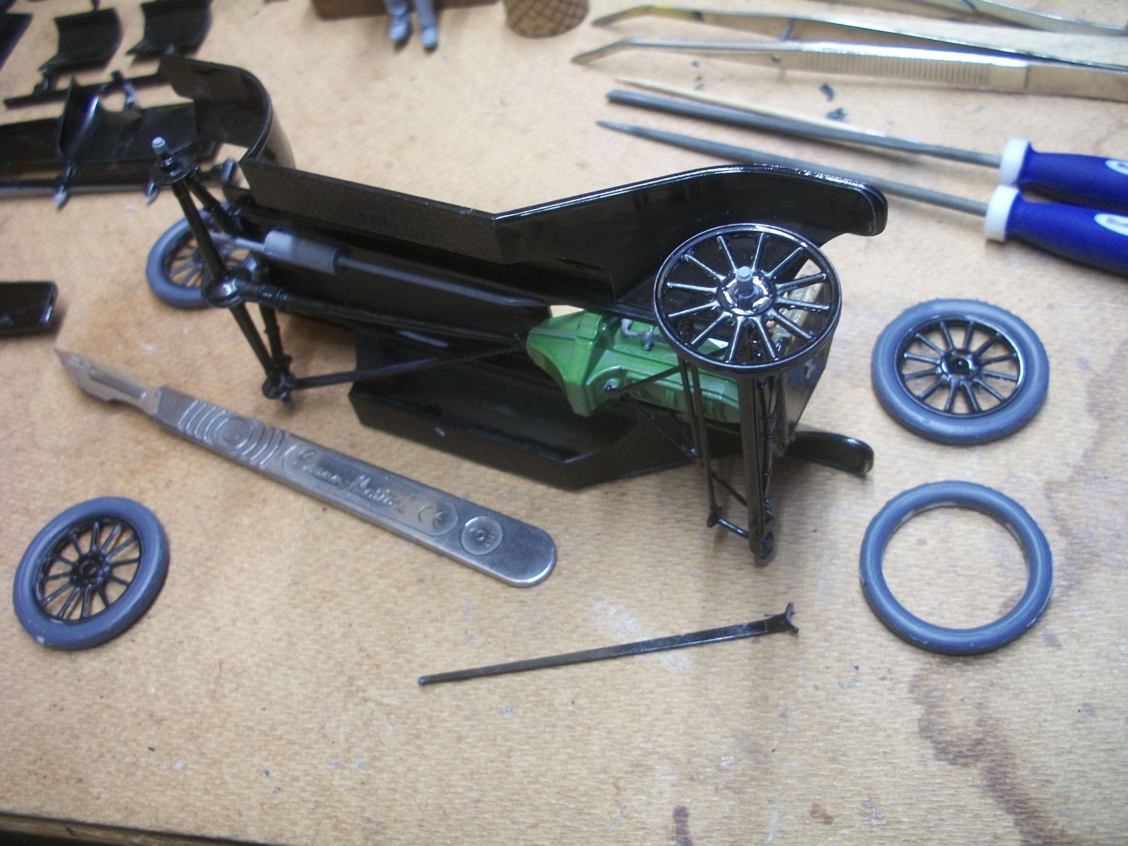
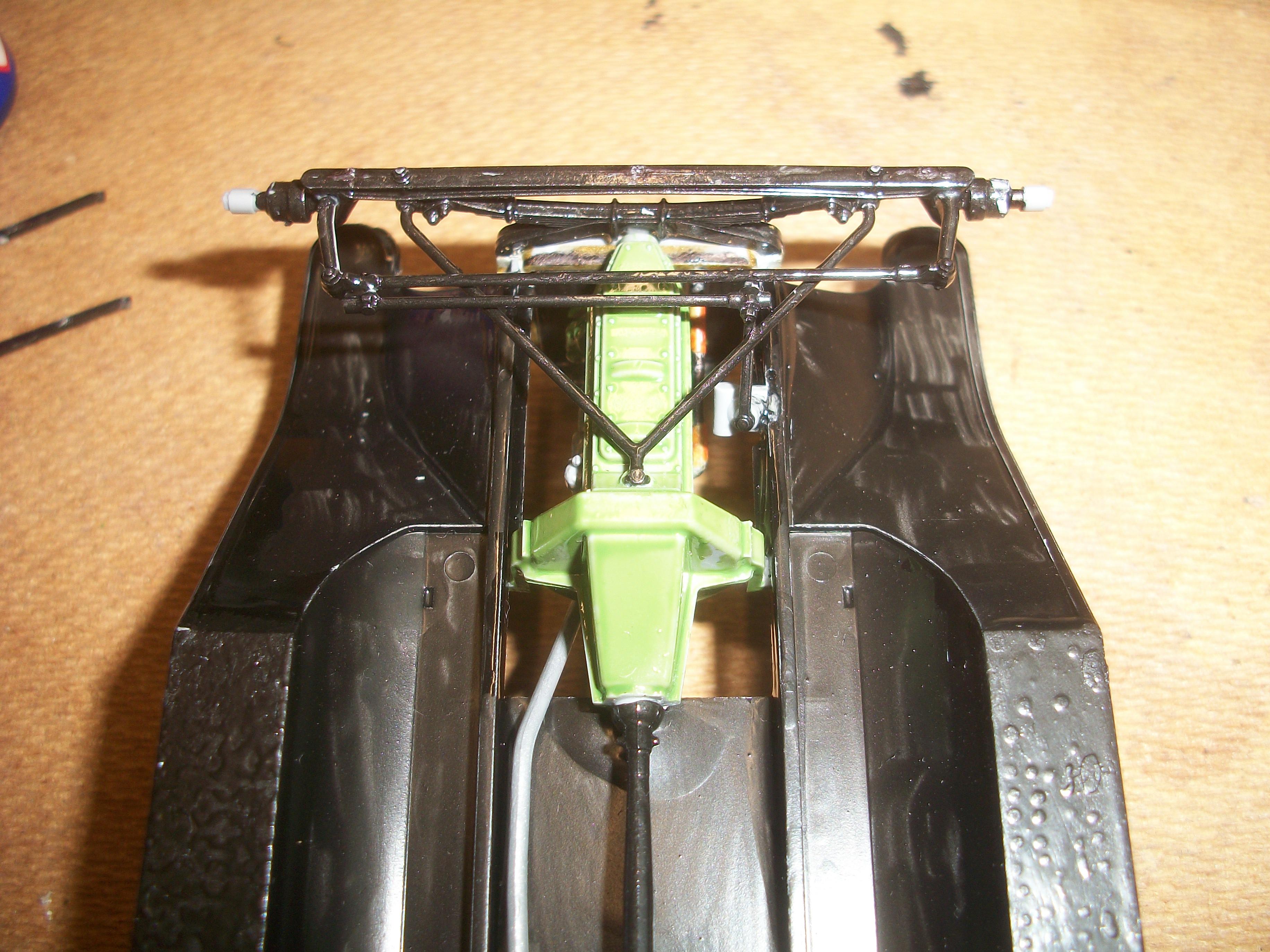
The various tie rods, steering arms, drop arm and bracing struts have been glued in place on the underside of the chassis. These were quite tricky parts to handle, as expected, but turned out alright in the end . . . Moving on to the wheels, these needed the dried black paint removing from between the spokes. This was carried out using a scalpel knife carefully. I found this process rather lengthy, but I reckon I have removed all of the dried paint. Now the wheels can be test fitted onto the hubs of the front and rear axles . . . By scraping away some excess black paint, and with a little filing, the wheels should go on to the hubs and also rotate freely. There will have to be some sort of outer washer or shim to prevent the wheels from coming off the axle. Thinking ahead to the video filming stage, I want the rolling chassis to be exactly that, ' rolling ' . . . The wheels and tyres look pretty good on this car, and all they will need is some further touching up with grey paint for the tyres and black paint for the wheel spokes . . . David
-
That was a good idea of yours to feed a length of insulated wire through the radiator coolant hose, which made me think of my carbide generator piping on the Model T . . . I agree that you do want some sort of basic interior door cards, even if the detail would not be seen once the taxi cab is assembled. Well done with the black paint finish on this body . . . Black does seem to be the most challenging paint colour to get right. These Aoshima models are of nice quality, and they have a different way of assembling the kit to Tamiya, for example. David W.
-
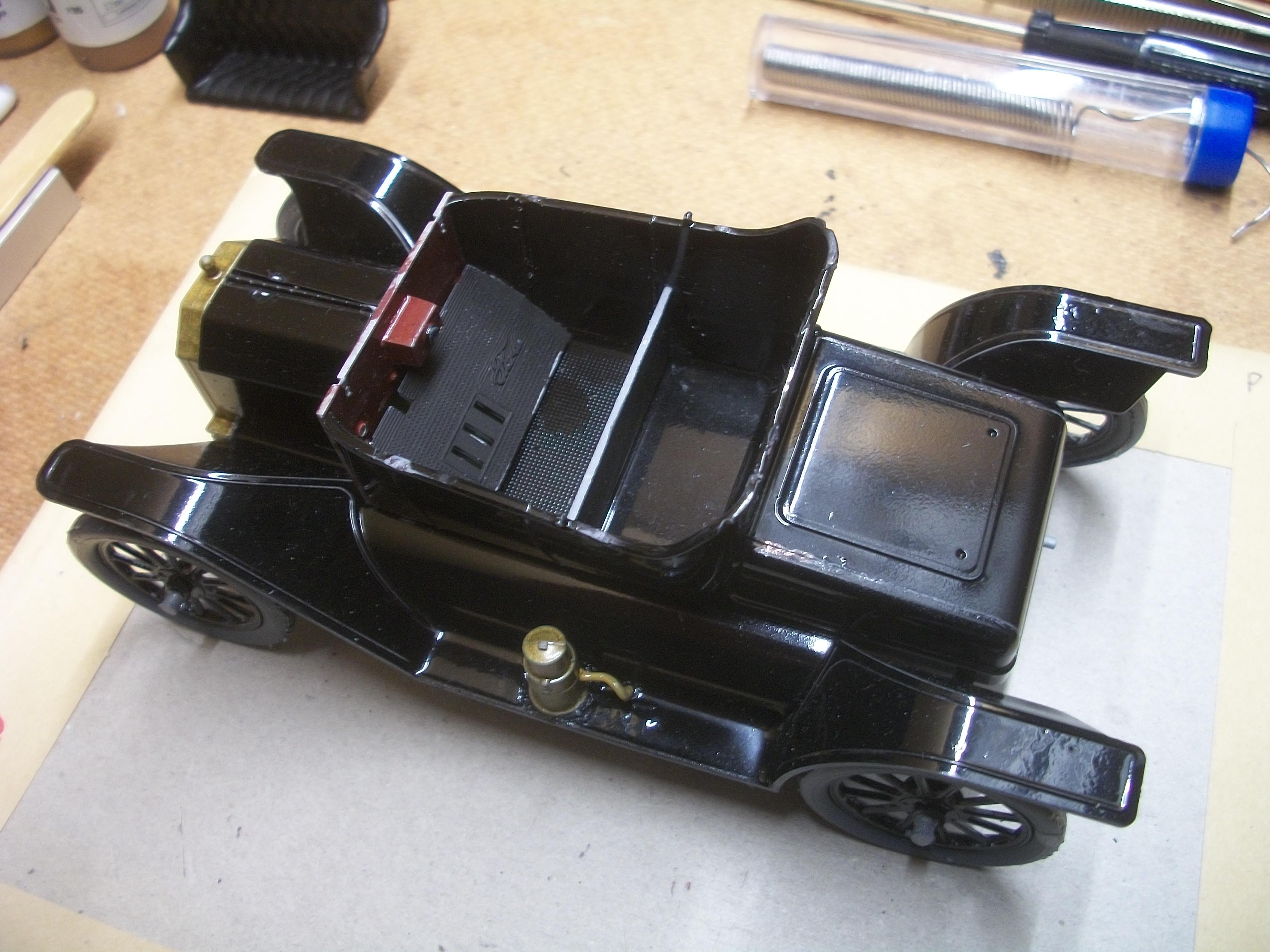
Today was all about applying some paint to the interior surfaces of the body panels, using Vallejo Glossy Black acrylic, and also coating the buzz box / trembler coils box with a mix of Vallejo Burnt Red and Mahogany Brown acrylic . . . This ' cherry wood ' paint colour was then used to touch up the firewall, and the frame on the firewall was painted Glossy Black to match the exterior body colour. David