absmiami
-
Posts
4,777 -
Joined
-
Last visited
Content Type
Profiles
Forums
Events
Gallery
Everything posted by absmiami
-
Tamiya McLaren MP4/6 build
absmiami replied to Josie's topic in WIP: Other Racing: Road Racing, Land Speed Racers
Yup -
Very nice Gramps now what is wrong with the “Lotus 33 chassis casting ?? ??
-
I’ll have to find one of motoi’s “happy man’s bibles” there should at least a partial listing. Or I’ll email Motoi. And mike quarterman would know ... Joker produced quite a few kits. - many were subjects that no one else has yet done in 24th scale. But they were not shy about copying stuff. As an example - they produced a kit Of the Lotus 49 Early spec. The ‘67 car. But they used a resin cast copy of the heller kit engine - mistakes and all ... still no one has solved the chassis riddle.... ??
-
Oh I forgot ... Motoi had a newsletter that he mailed to you - that’s right -he MAILED it to you. Full of xeroxed images of stuff currently available So I would take it to lunch and drool all over it in between bites of my Wendy’s chicken sandwich. I still got one or two somewhere ...it’s funny what us resin addicts used to have to do to get our fixes... ranchero. Have a look at some good chassis photos. Any book on Lotus you might have by Doug Nye will answer the question about the question ...
-
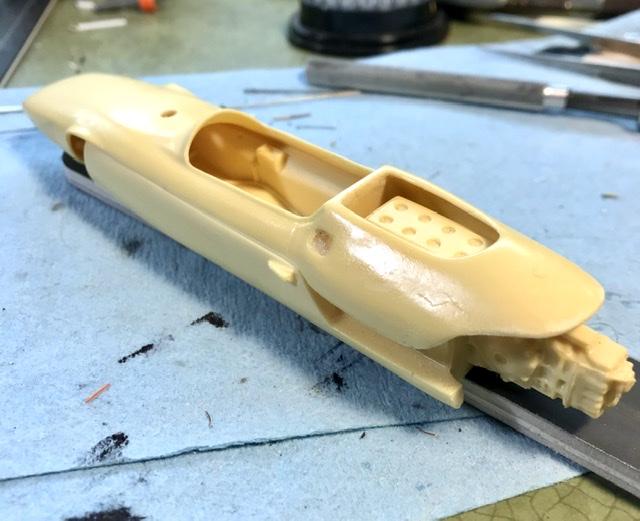
The Joker kits are rare and are not often ebayed - and yes they are good kits of Race cars from my favorite era - in my favorite scale ... But about this chassis ... ...
-
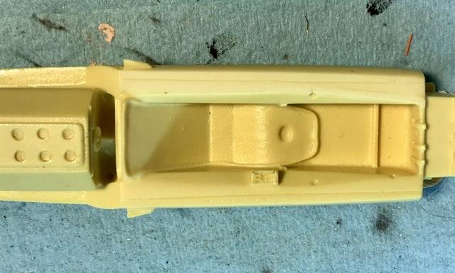
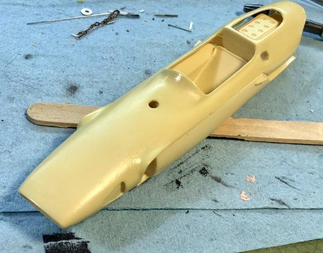
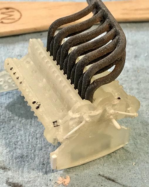
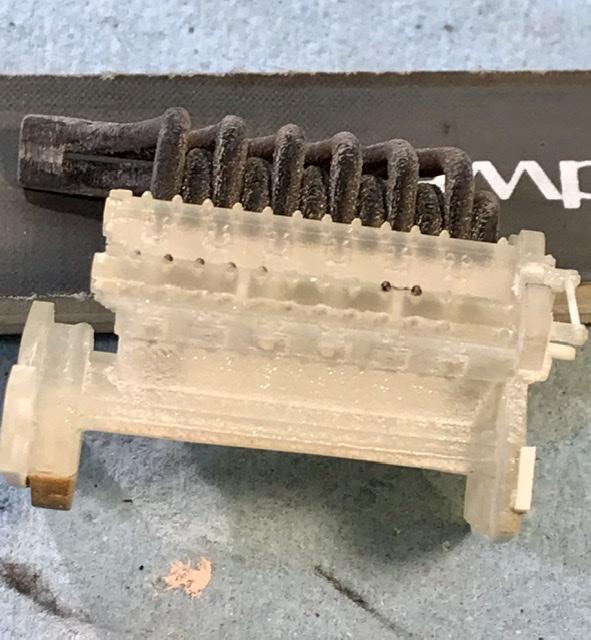
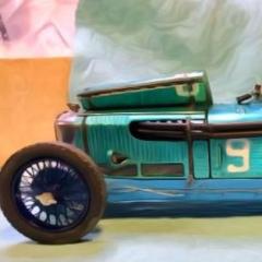
These photos were done after some minimal cleanup. The castings have some light flash and a few holes on the casting edges. Nothing too bad. In fact for their age - these were quite good. but look carefully at the chassis in the first two photos - those of you who obsess over Chapman’s chassis engineering (I know you’re out there) will notice a couple of three inaccuracies - features that render the casting inaccurate for the Lotus 33 monocoque gold stars to the first obsessive to identify these errors ....

-
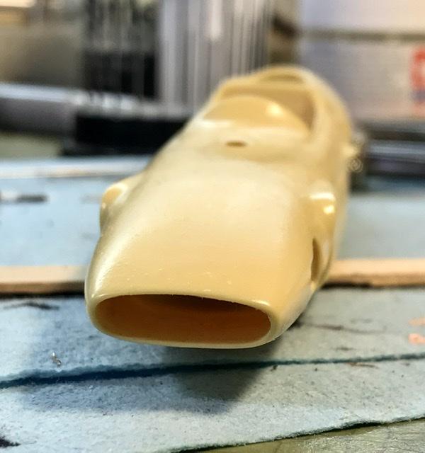
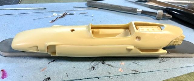
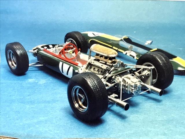
Forgot to mention the scale for those of you too tender in years to know of the Joker kits - they made a series of 24th scale kits - sports cars and GP cars in the early years of resin/craft kits - before the age of the internet ... They were made in low numbers and sold through distributors. Back in those days Motoi (calif) was my resin “pusher”. I would scour his ad in Mike Quarterman’s magazine and send Motoi my orders - with a check - never quite sure what would arrive in the mail three weeks later ... So you can see from the photo that these kits could actually produce a very nice 24th scale model ...
-
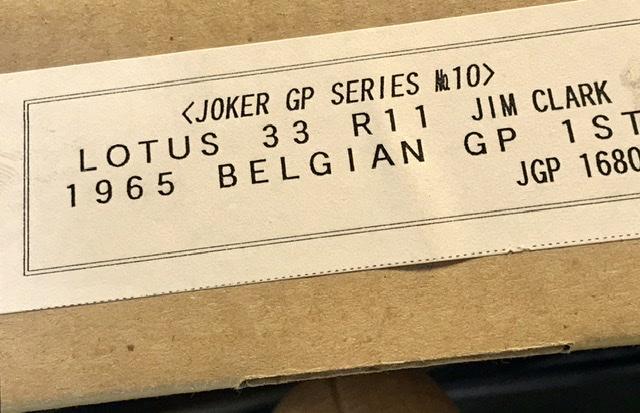
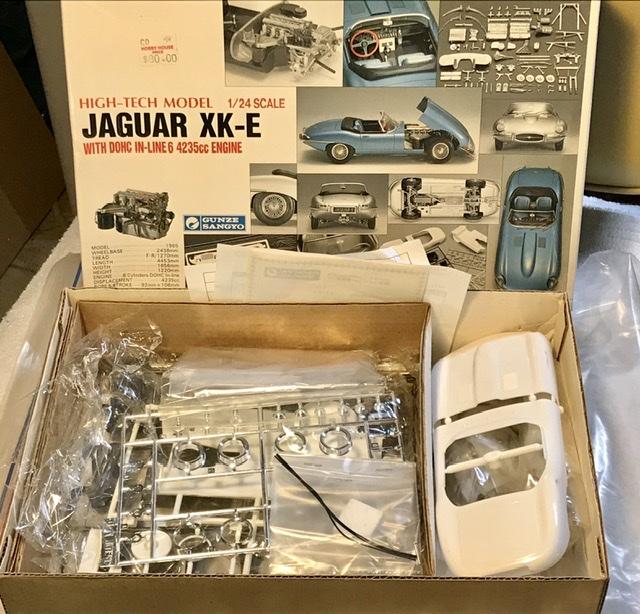
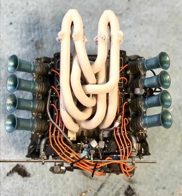
This will be fun ... and confusing first I wanted to open a new build topic on my phone - trying to pretend that I’m not too far behind the “curve” second What you are looking at is a twenty five year old Japanese resin kit by Joker. Got it many years ago and I finally figured out what To do with it... but that’s complicated ...
-
The mysterious Gunze kit ... expensive. Includes some photo etch. Lots of white metal. Need to build it. Should turn out well Didn’t know about the new revell Of Germany kit ...their D type Sports car was a near miss. Engine was only okay ...Let’s see how it turns out ...
-
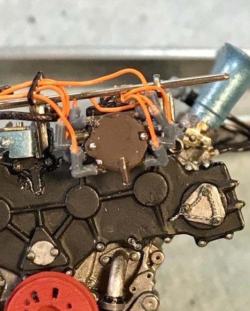
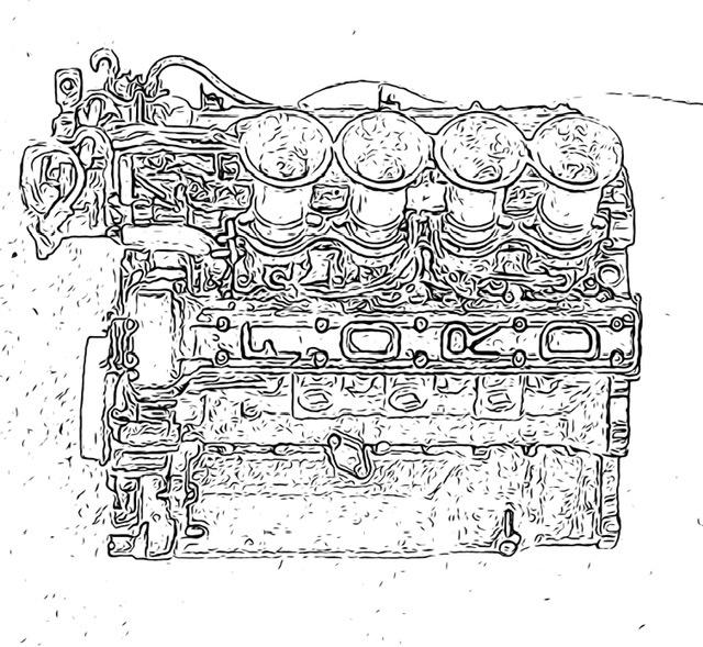
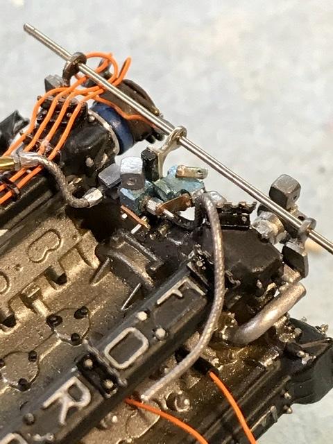
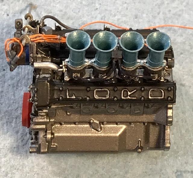
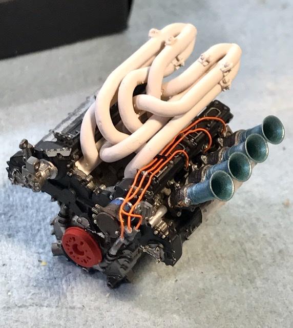
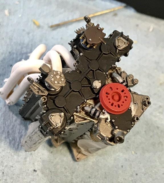
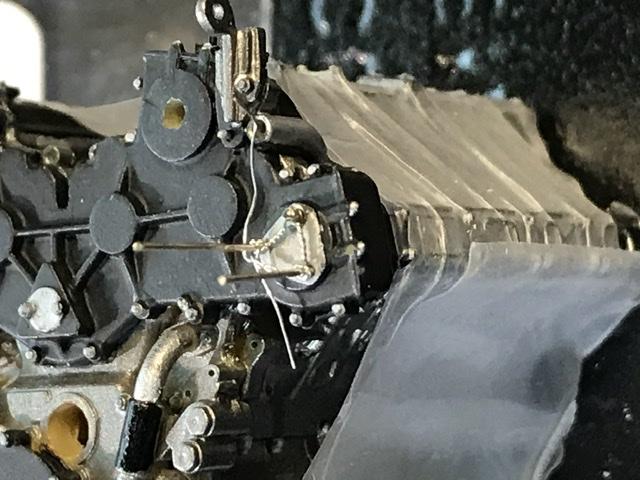
I think I’ll do the distributor differently on the next one. If the terminals are made with brass tube - you can slip the plug wires in and not worry about the connection... the fuel lines have to sneak around The plug wires and I still need to squeeze in the throttle linkages. A right fit...
-
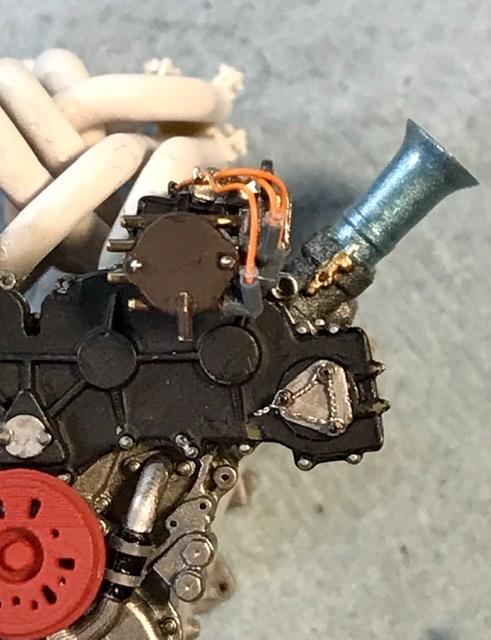
Dept of corrections the distributor plug boots are fr RB Motion ... and CA glue won’t bond the plug wire to the boots. But some epoxy with some CA seems to hold things together...
-
Treat yourself to the Heller XKE coupe. Better than the Revell. The Heller kits give you everything you need for a good replica of either the coupe or the convertible And lets start A great big argument about which was the better looking sports car ...
-
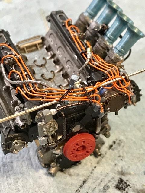
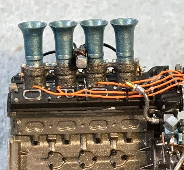
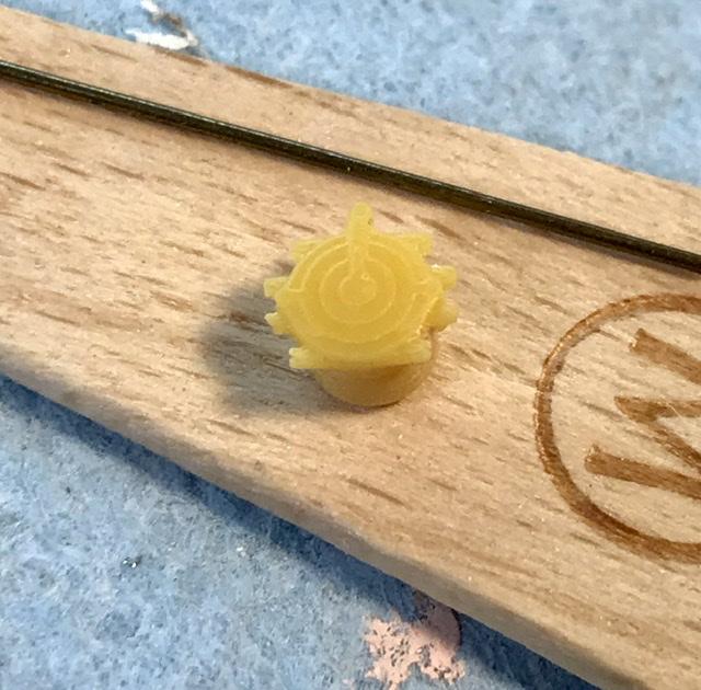
Spark plug 4 crosses over to the far side of the distributor. With the left side plugs in place I glued the left side fuel lines in and then glued the fuel injection unit to the cyl head at this point I glued the fuel distributor assembly to the front of the engine. Next I’ve got to finish making and attaching the linkage for the fuel and place the right side plug wires with looms fuel line hardware from RB motion the fuel lines are made from .024 tin wire that is rolled under a file to make a finish that looks like steel fuel line it’s very soft . So I’m not concerned with breaking any of my joints/connection points
-
Gracias
-
The Jim stokes built spare parts Alfa Romeo 158 is stalking me. it was featured on Ant the mechanic’s motor trend channel TV show. What a race car ...
-
Tamiya McLaren MP4/6 build
absmiami replied to Josie's topic in WIP: Other Racing: Road Racing, Land Speed Racers
Spa ... l’m jealous - near the top of my bucket list - some day .... -
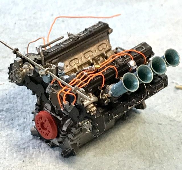
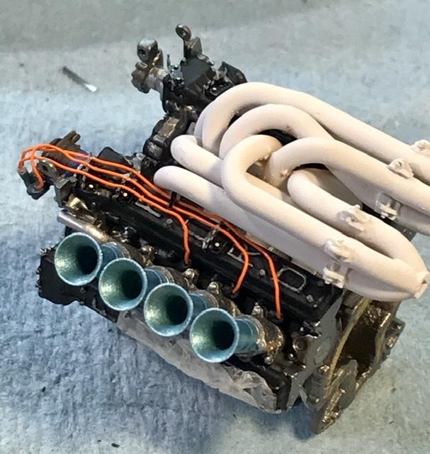
Time for the sp plug wires ... decision / advise to use the smaller diameter plug wire was correct ... the distributor boots are from replicas and miniatures - thank you norman the Plug looms and wire are detail master. The photo-etched looms are doubled - per instructions- and yes this gives a better dimensional appearance Wires are CA glued to the looms and the boots are CA glued to the distributor ... 3 down and 5 to go And I’ll make two additional looms for the wires traveling to the opposing cylinder head i think this Is actually going to work ...
-
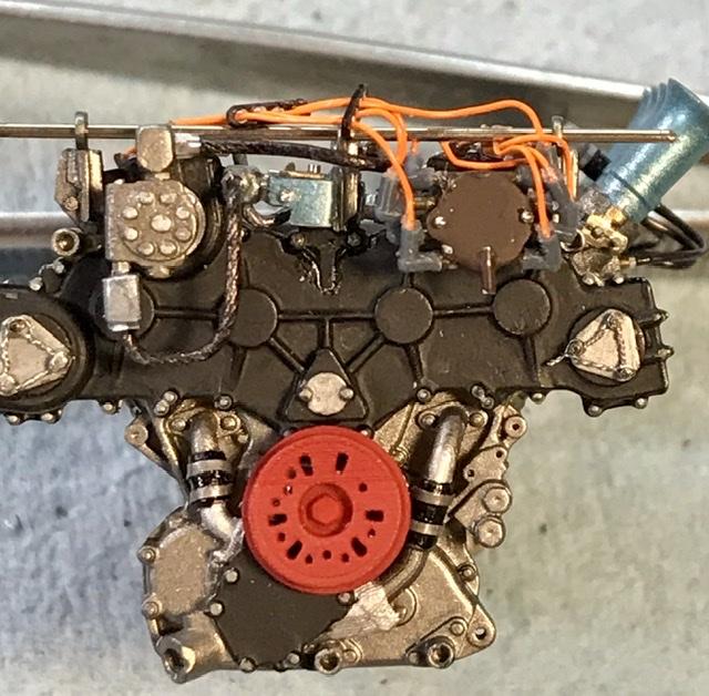
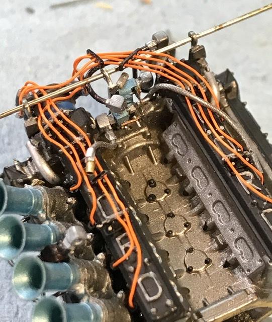
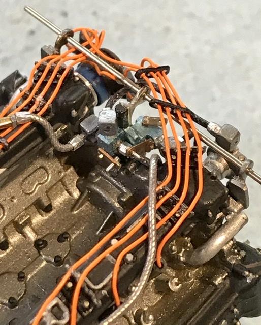
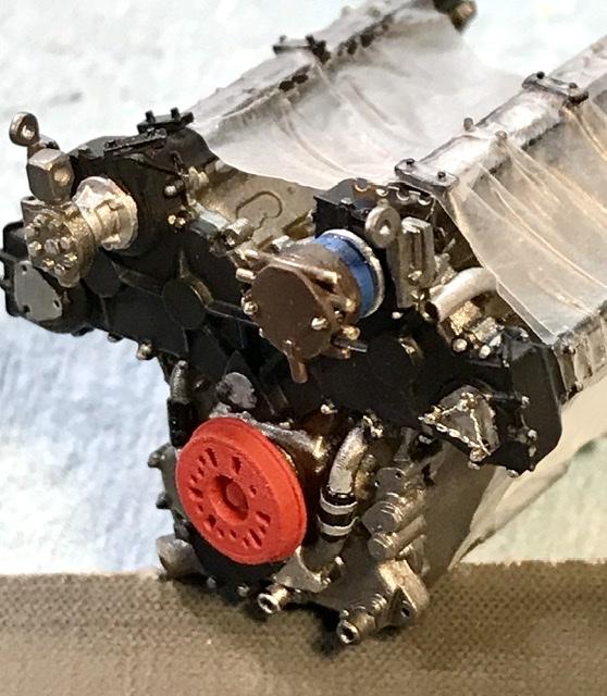
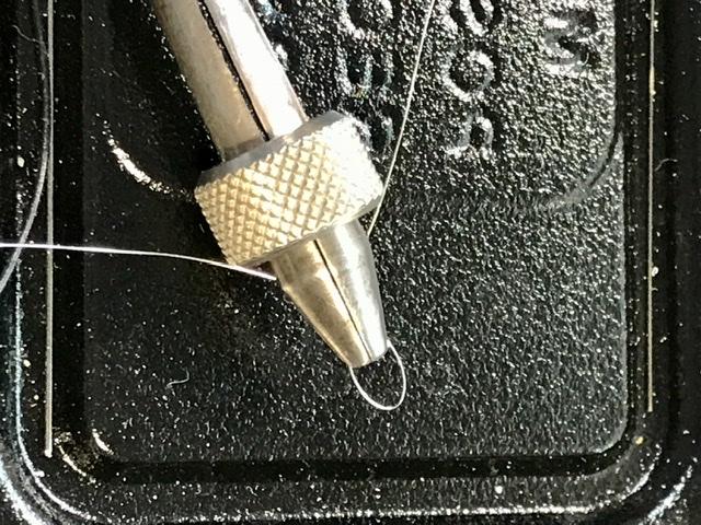
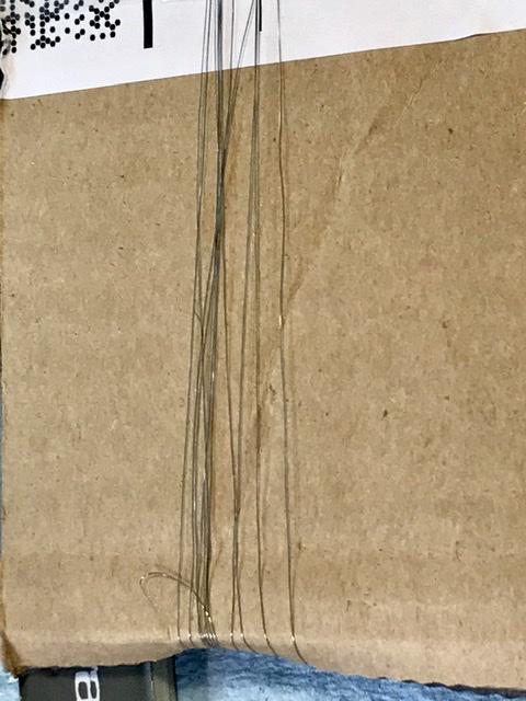
Second shot shows the tool I use to make the safety wires ... a fool’s errand - and only justified on a display engine ...
-
Good advise. And you know how carefully I listen to advise ... why don’t you get mr bill’s consent to post the Cisitalia engine shots here .,.
-
Tamiya McLaren MP4/6 build
absmiami replied to Josie's topic in WIP: Other Racing: Road Racing, Land Speed Racers
Favorite track - location ? You’re too young to have wrenched at Watkins glen?? -
Tamiya McLaren MP4/6 build
absmiami replied to Josie's topic in WIP: Other Racing: Road Racing, Land Speed Racers
Nice! what paints did you use or mix for the gearbox ? and where did you see Senna ?Montreal ? I saw him at Montreal early in his career - in a Lotus - had the impression that the driver was better than the car - he was driving the wheels off it ... -
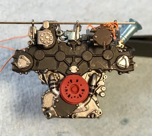
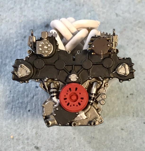
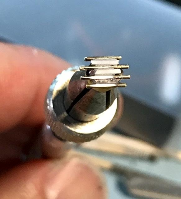
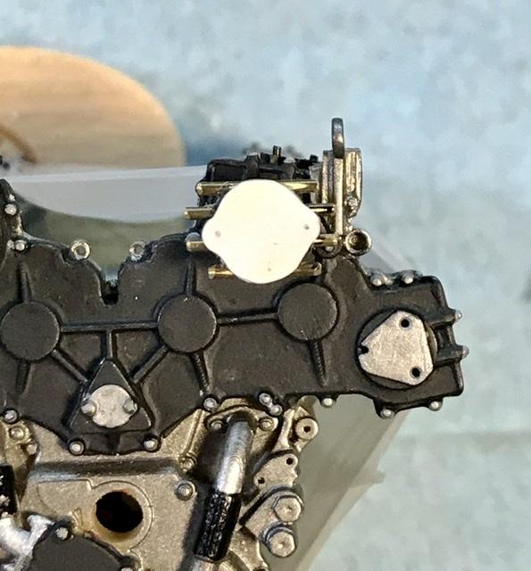
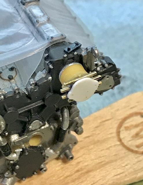
Should I build the frame in evergreen plastic or brass ??? whilest I ponder ... work on the DOHC distributor and some safety wire on the gear cover passages. I replaced the terminals on the distributor to get a more secure attachment point for the distributor caps that Norman Veber makes/sells ... the safety wire is twisted.005 wire. Think I bought it in amazon - yrs ago.
-
Should I build the frame in evergreen plastic or brass ???
-
Oh dear. You’re sending me down another rabbit hole. The stokes build was featured earlier this yr in Motorsport - I think- with an awesome overhead shot of the completed chassis. But these additional shots are great and they are by my favorite author. Mr Nye. Well my second favorite. Hunter Thompson is numero uno. I do plan to build a frame for the Alfa engine And I must decide if I’m going to build it into the Merit kit body or just display as a stand alone. I change my mind every time I think about it .... And now you’ve made me think about it again
-
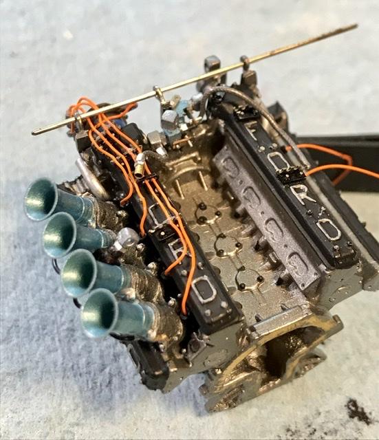
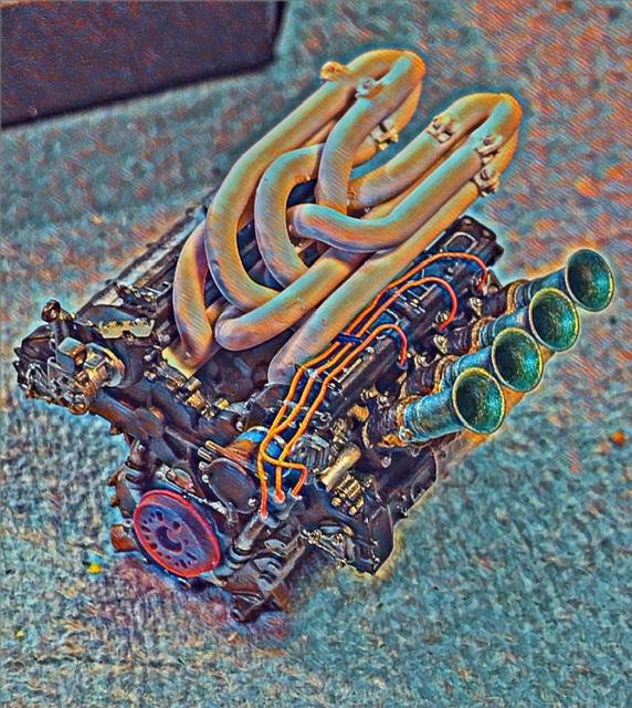
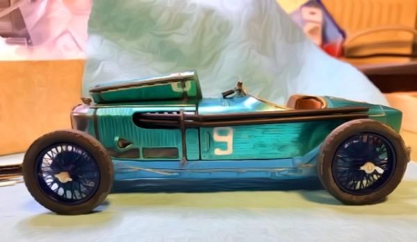
So actually the engine block and valve covers had a “machine turned” Finish. Which gave them a bright silvery appearance. You know what plans I have for the body. Don’t think I can do that for the engine I’ll damage too much of the bolt detail. So I’ll just wing it. And find some deep blue color for the cyl head ...