absmiami
-
Posts
4,779 -
Joined
-
Last visited
Content Type
Profiles
Forums
Events
Gallery
Everything posted by absmiami
-
Cooper barn find
absmiami replied to absmiami's topic in WIP: Other Racing: Road Racing, Land Speed Racers
Was wondering whether it was sold in smaller tubes than what I saw on amazon - 14 oz ? Too much - assuming it does not have long shelf life ... -
Cooper barn find
absmiami replied to absmiami's topic in WIP: Other Racing: Road Racing, Land Speed Racers
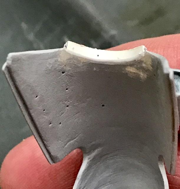
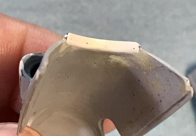
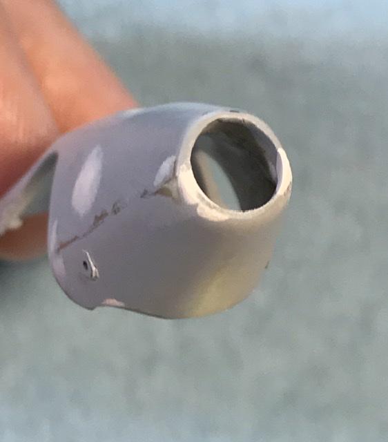
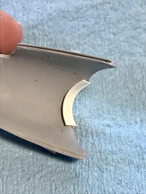
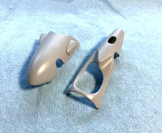
Thanks but I always worry about what’s round that corner .... bondo morning .... blending the lip for the windscreen and correcting some flaws on the engine cover has anyone tried the 3M acrylic glaze putty ???
-
Italeri Alfa 8c- WIP
absmiami replied to jaymcminn's topic in WIP: Other Racing: Road Racing, Land Speed Racers
Me too inquiring minds want to know - which medium did you try ? -
Cooper barn find
absmiami replied to absmiami's topic in WIP: Other Racing: Road Racing, Land Speed Racers
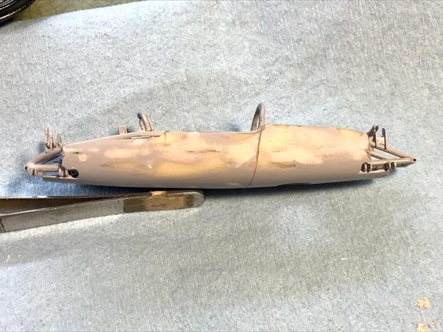
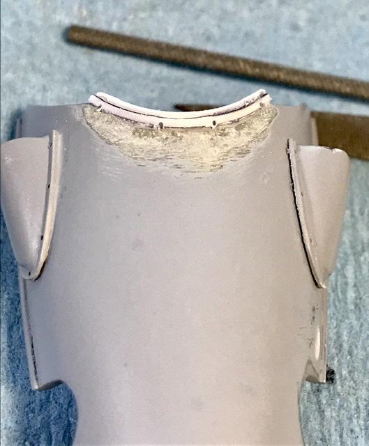
Beaches still closed. But there is lots of sanding to do... 2 part bondo finishing putty. I think #108. Just the stuff on the shelves at your local hardware store. Pinholes be gone (?!?). Also adding the lip for the windscreen...
-
Cooper barn find
absmiami replied to absmiami's topic in WIP: Other Racing: Road Racing, Land Speed Racers
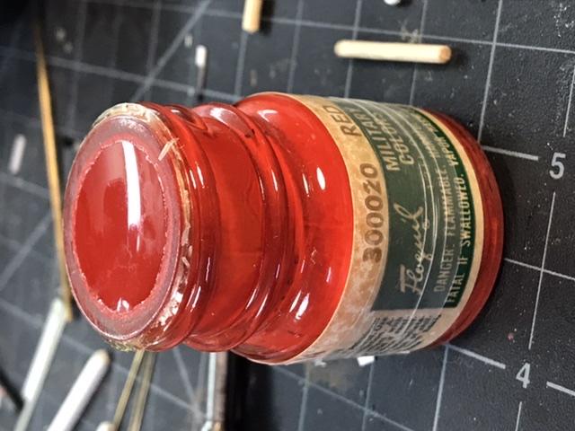
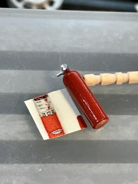
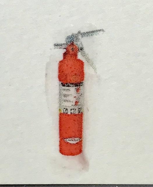
Fire extinguisher found another stash of floquil in one the deepest recesses of the workshop - nice surprise - including a jar of red unopened from maybe ???? 25 yrs ago ???? Very flat - so topped with some Tamiya clear and the decal made on my printer mite try a redo of the markings with a strip of white laid over the markings and then a second decal over the white ....
-
Cooper barn find
absmiami replied to absmiami's topic in WIP: Other Racing: Road Racing, Land Speed Racers
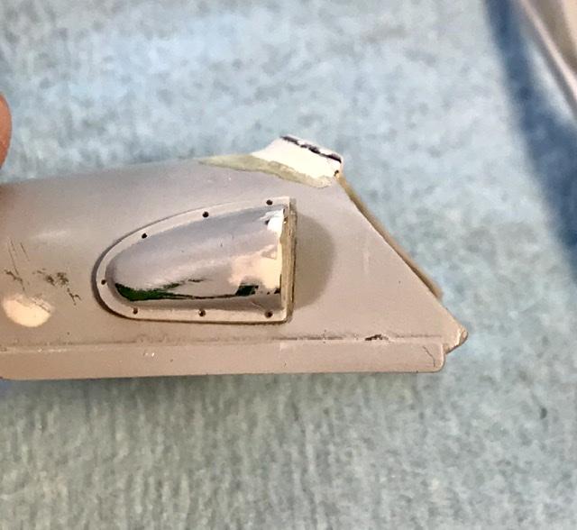
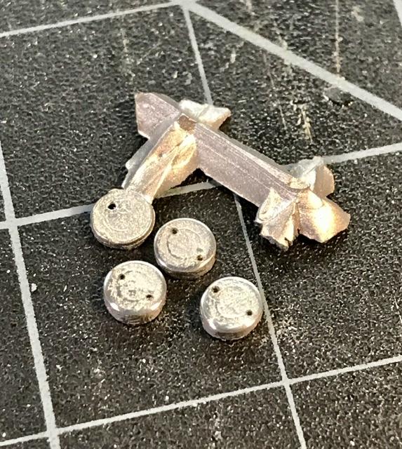
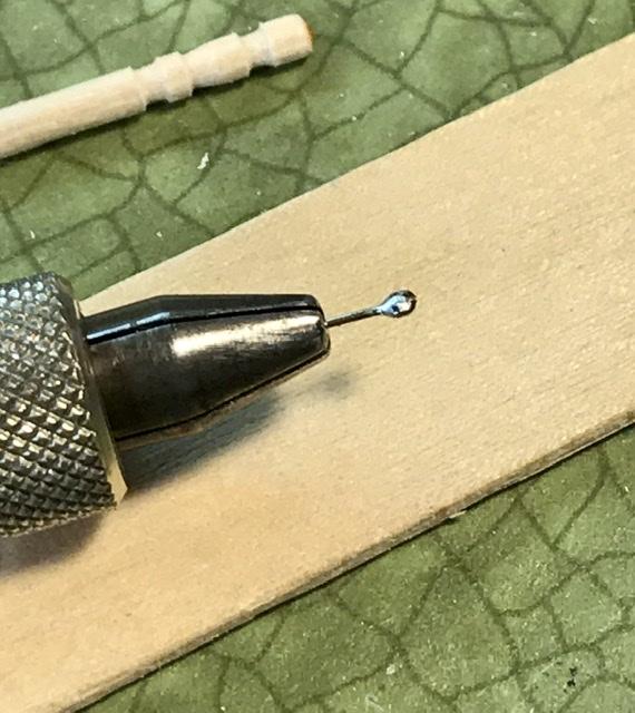
Herb Deeks’ kit came with these white metal spinners for the wheels - temporarily glued to the end of a toothpick and sanded/finished with the Foredom drill and drilled for rivets ...
-
Cooper barn find
absmiami replied to absmiami's topic in WIP: Other Racing: Road Racing, Land Speed Racers
Tried some oil based Sharpie black on the sway bar - looks ok - shiny - needs a short while to dry the suspension uprights were brush painted with some floquil - brushes on nicely - wish I had a bigger stash of these paints ...
-
Cooper barn find
absmiami replied to absmiami's topic in WIP: Other Racing: Road Racing, Land Speed Racers
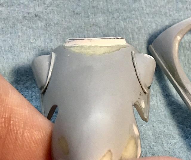
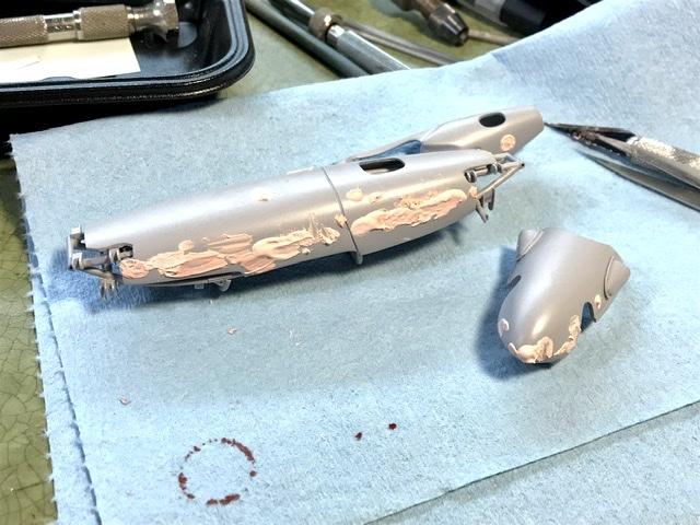
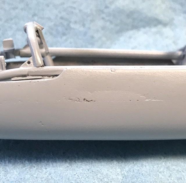
It’s primer nite some pinholes here and there no big deal ... bondo tomorrow ... the chassis will remain primer gray -‘Tamiya - I’ll brush paint the interior aluminum finish on the body panels
-
A hobby store? what’s that....?....
-
Cooper barn find
absmiami replied to absmiami's topic in WIP: Other Racing: Road Racing, Land Speed Racers
So Gramps46 did you know that there was a bar in Wynwood in Miami named after you ?? www.gramps.com one of my favorites … I miss it …. ………. -
Cooper barn find
absmiami replied to absmiami's topic in WIP: Other Racing: Road Racing, Land Speed Racers
-
Cooper barn find
absmiami replied to absmiami's topic in WIP: Other Racing: Road Racing, Land Speed Racers
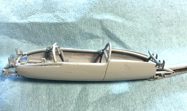
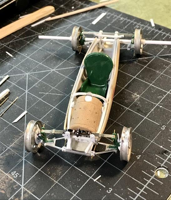
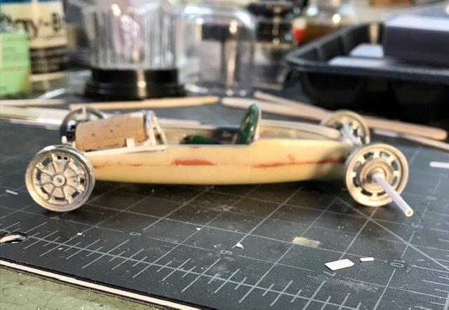
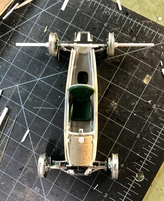
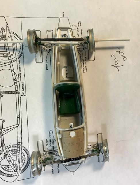
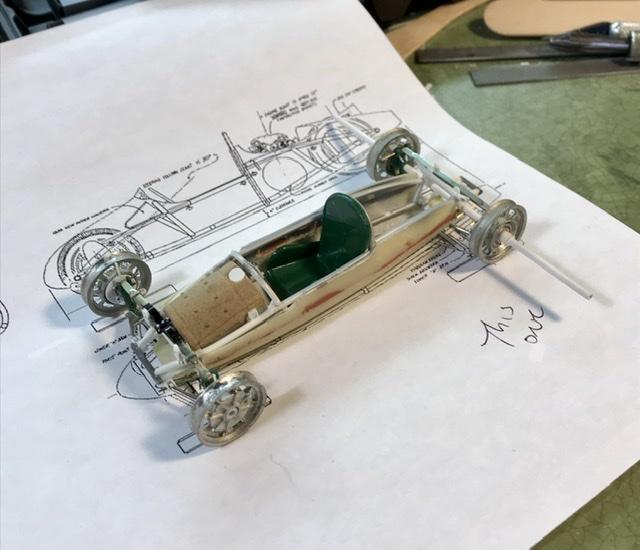
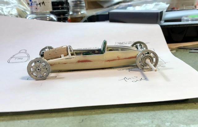
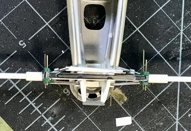
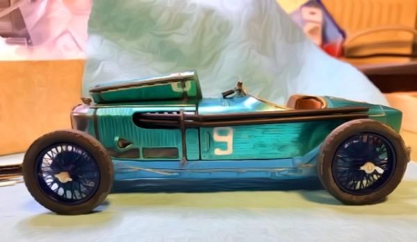
Every so often the modeling gods smile upon us ... when I made the frame and glued on the susp arm brackets I was not too sure that the model would have the correct stance. But two years later the wheels are on and the stance is just right ... sitting on the scale plans - the wheelbase is about one scale inch too long and the front wheels are a little too wide - but the fronts are supposed to be wider than the backs - and the main thing is that the stance is right.... still need to make the rear sway bar ...
-
Cooper barn find
absmiami replied to absmiami's topic in WIP: Other Racing: Road Racing, Land Speed Racers
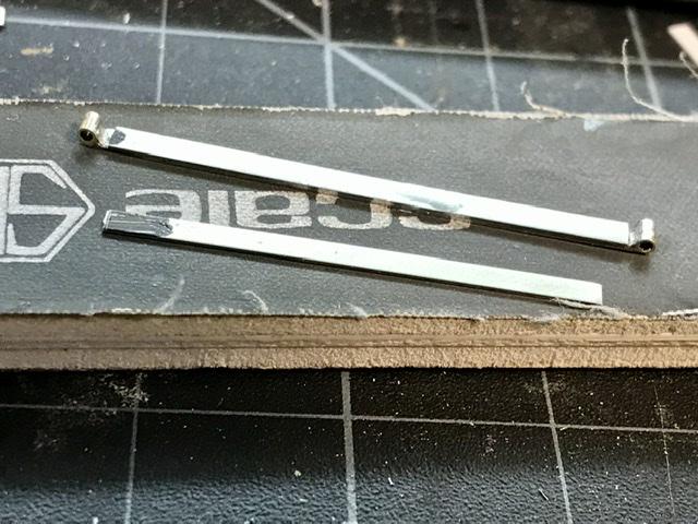
Rear leaf spring. 3 strips of nickel bar soldered together ... now it’s time to pin the fr suspension back together to see how the mark 9 sits ....
-
Cooper barn find
absmiami replied to absmiami's topic in WIP: Other Racing: Road Racing, Land Speed Racers
Sir Stirling Moss has passed away he raced this car in some vintage events years ago - Rest In Peace Thinking again about starting a build of his Rob Walker Lotus 18 - and/or his privateer Cooper ..... Thanks Reverand Davis .... which merits do you have ? Do you have both maseratis ? Now to the rear leaf spring. Same assembly and material as the front - but it is slightly shorter ...
-
Cooper barn find
absmiami replied to absmiami's topic in WIP: Other Racing: Road Racing, Land Speed Racers
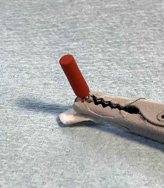
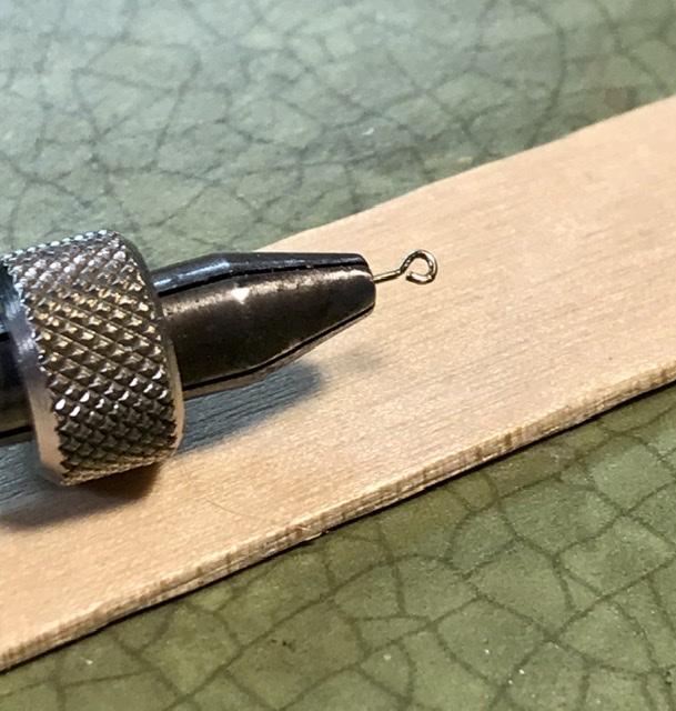
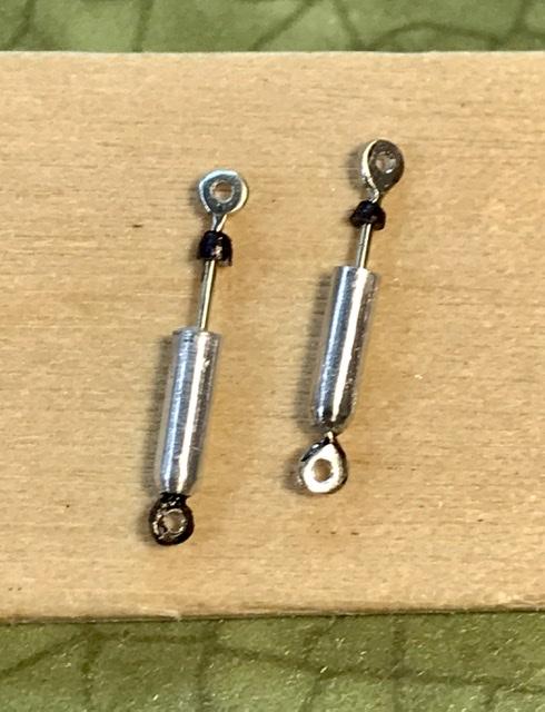
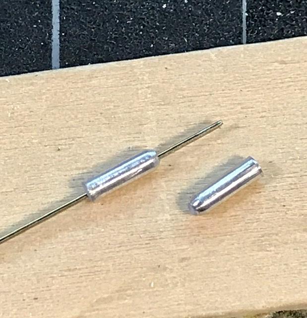
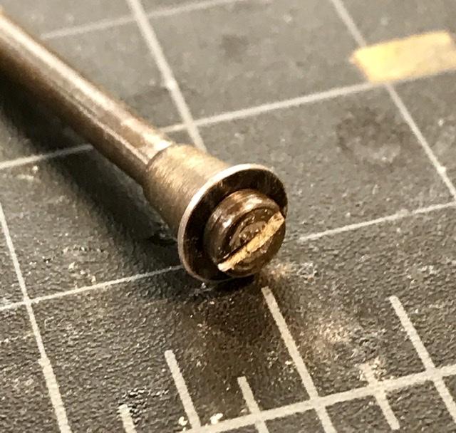
No worry. The plunger length will be adjusted during assembly - the eyes are made as per the eyes for the shift linkage ... the shocks will be finished in black ... has anyone tried the oil based sharpies yet ??
-
Cooper barn find
absmiami replied to absmiami's topic in WIP: Other Racing: Road Racing, Land Speed Racers
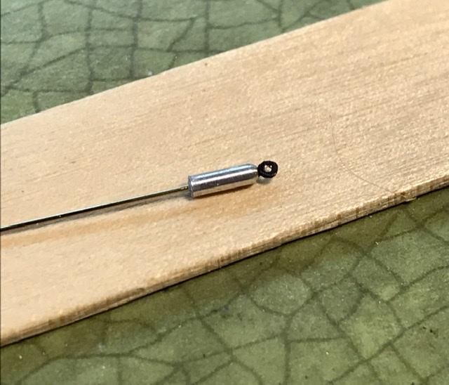
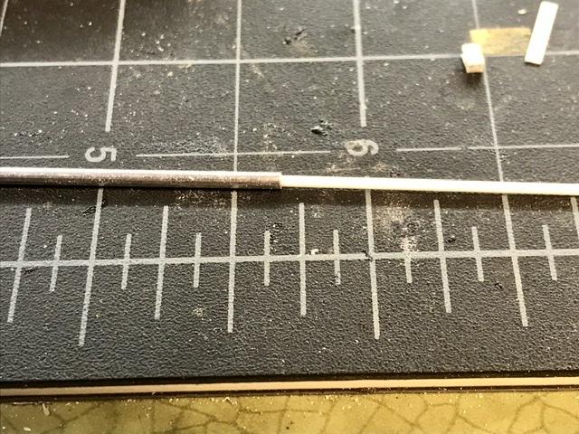
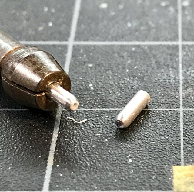
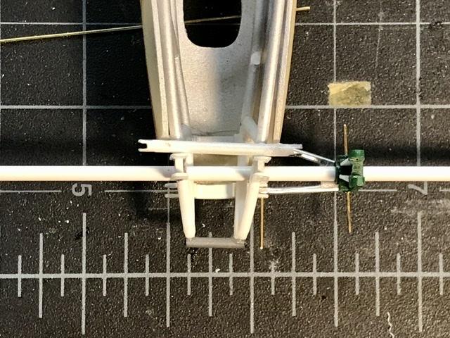
Time to make the rear shocks ... made from a short length of alu tube - 16th - with plastic plugs at either end - drilled for .019 nickel rod for the shock mount eyes and the plunger ...
-
Cooper barn find
absmiami replied to absmiami's topic in WIP: Other Racing: Road Racing, Land Speed Racers
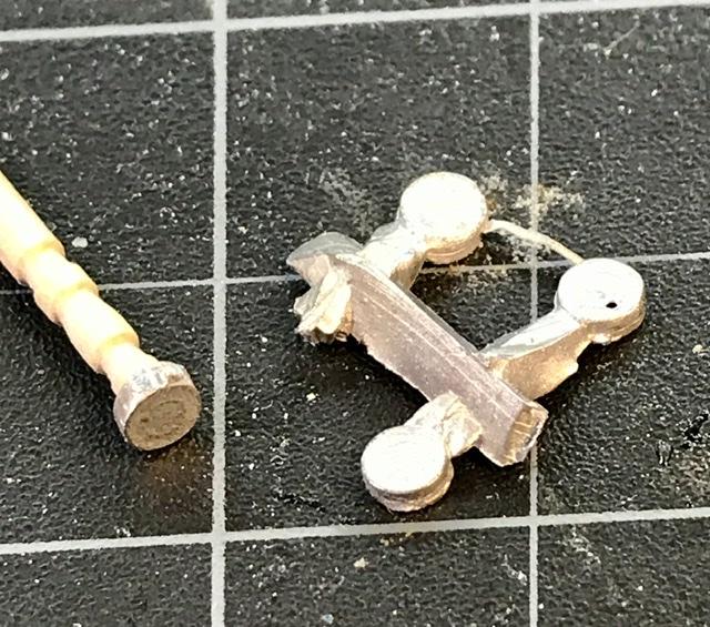
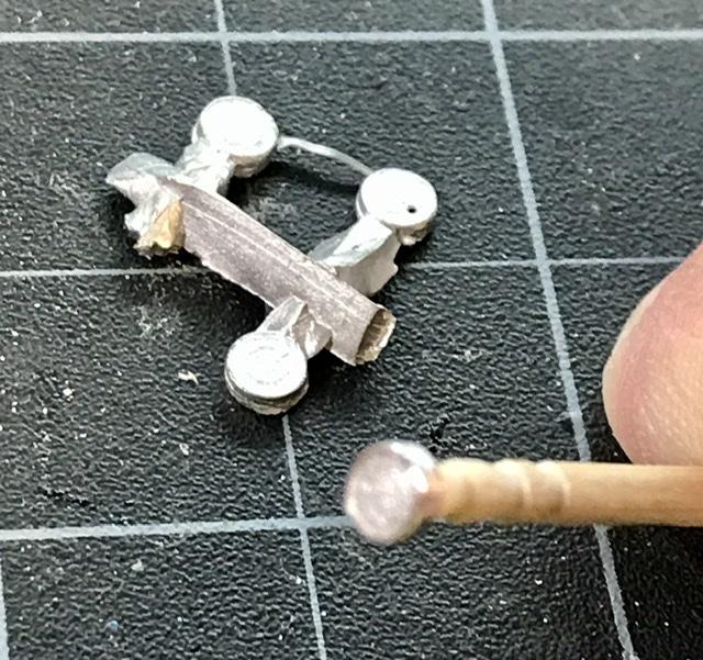
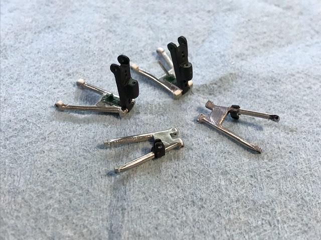
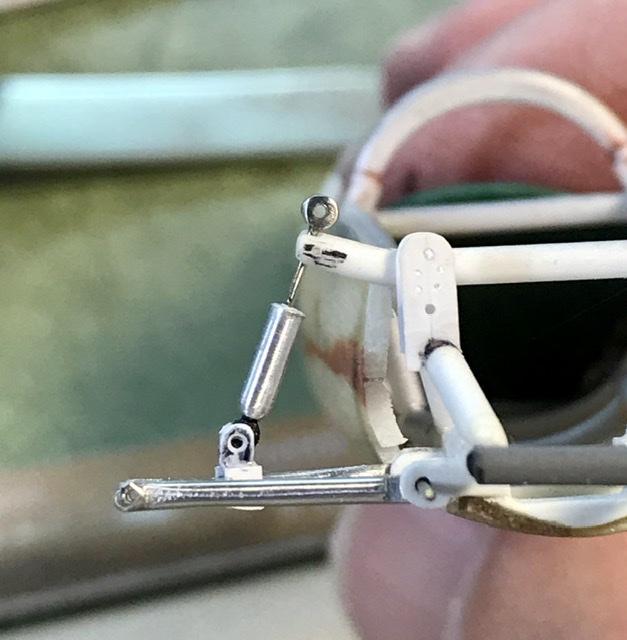
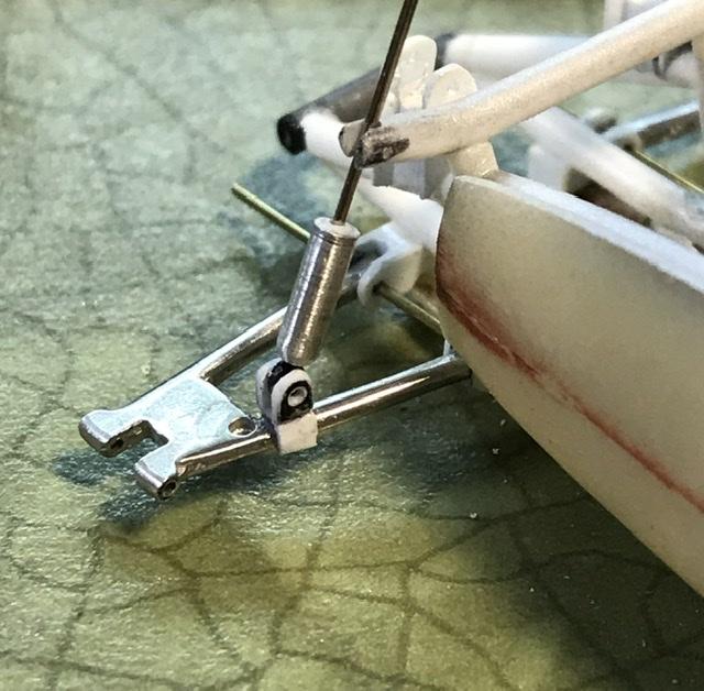
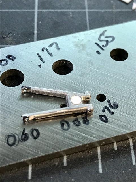
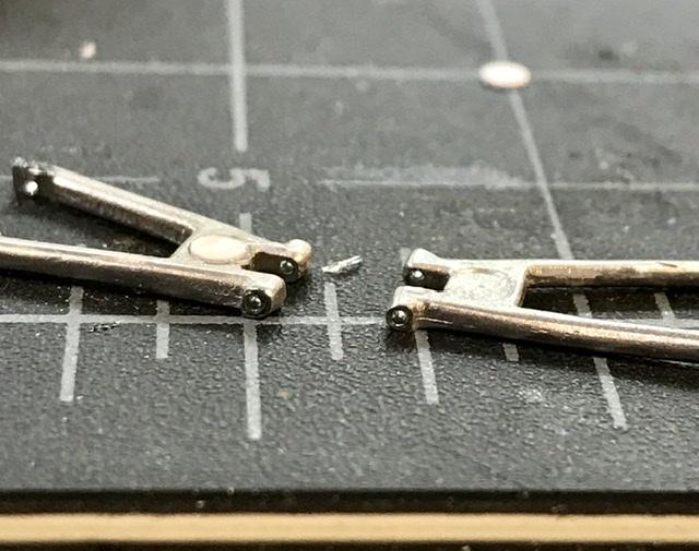
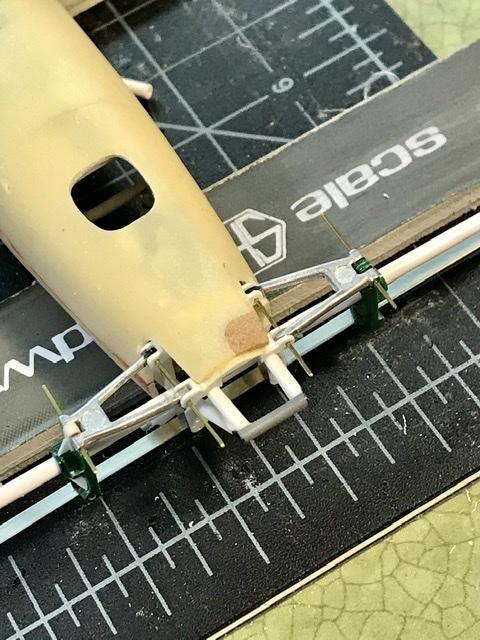
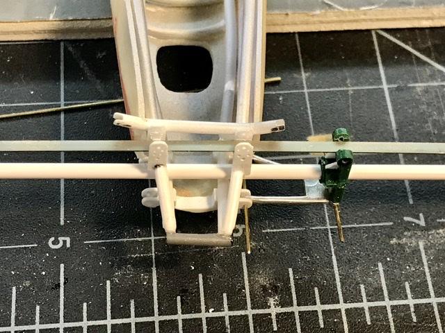
2 things The susp arms wh metal castings retain the sink marks fr the merit injection moldings . So I punched out a couple of .010 filler discs and glued them into the recesses thing 2. The susp arms have shock mounts welded onto the forward members. So I made the mounts from two pieces of evergreen square bar - filed, drilled for bolt holes, sanded, then glued to the arms ...
-
Cooper barn find
absmiami replied to absmiami's topic in WIP: Other Racing: Road Racing, Land Speed Racers
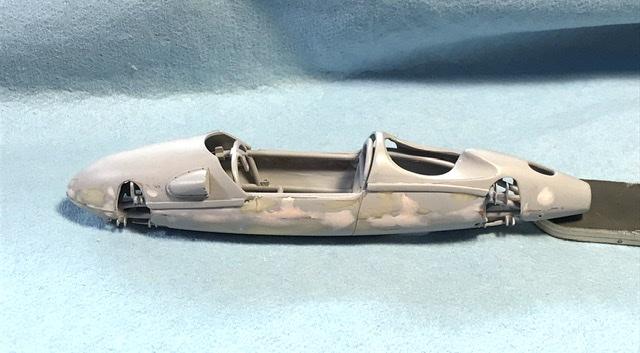
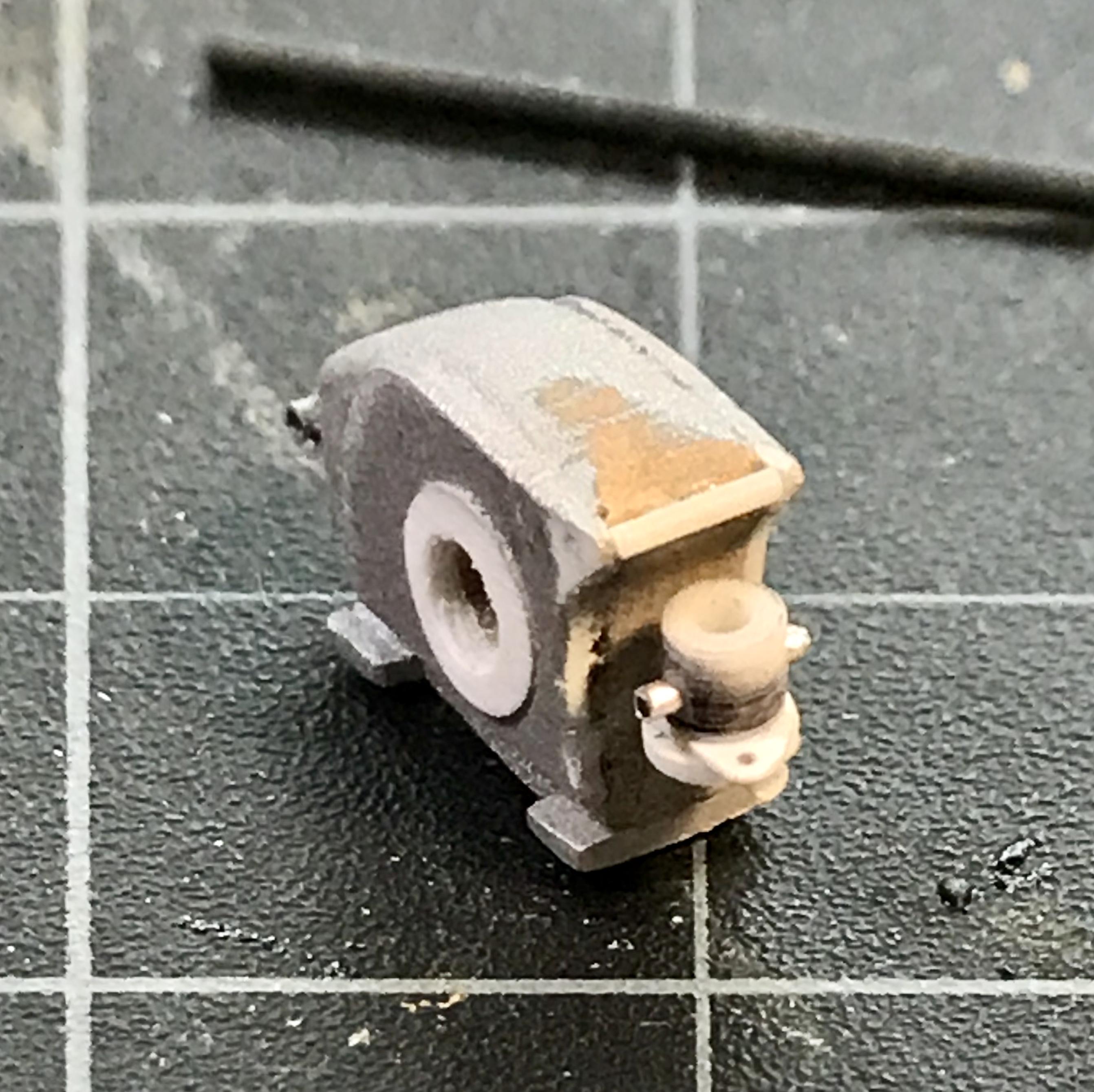
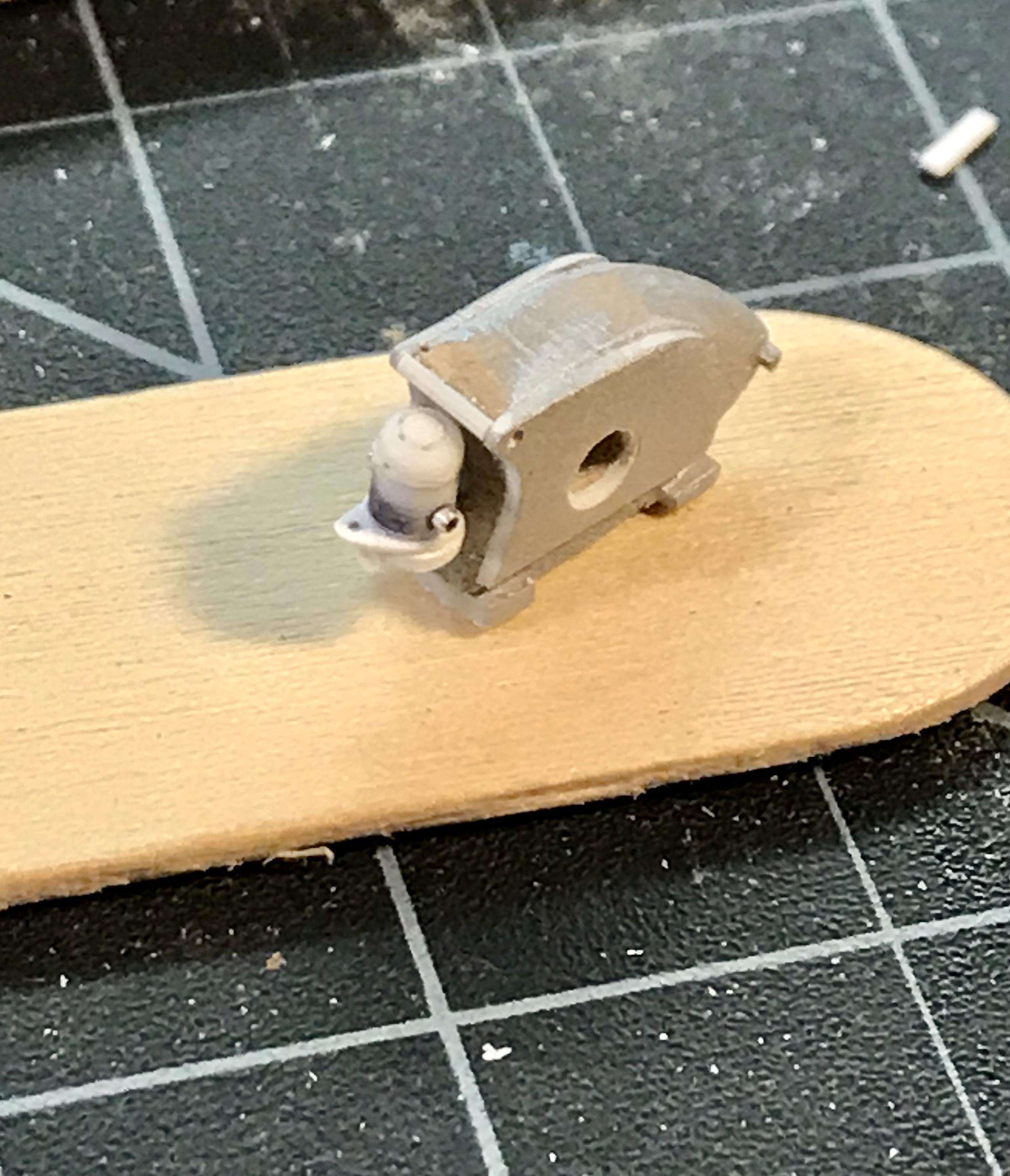
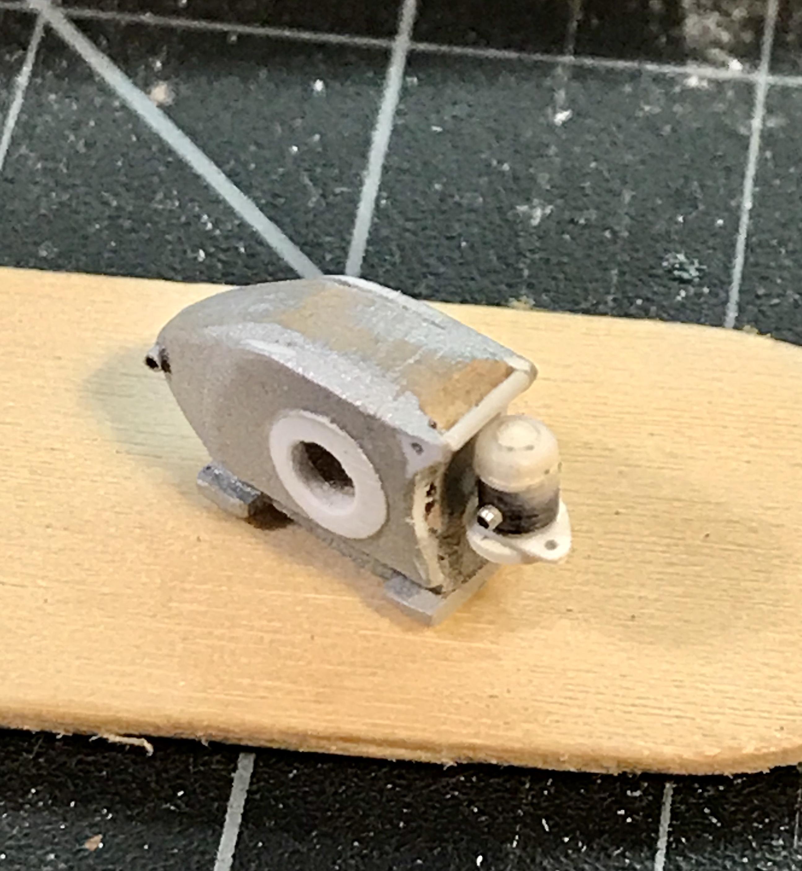
Thanks gramps. But have no fear. The front and rear panels will both hinge the only stuff that will be hidden will be the pedals under the fuel tank but I do plan to make a couple of panels off/chassis only cars how about a vanwall? And maybe a lotus 18? the fuel pump is mechanical and is driven off of the back of the transaxle. Yes - the fuel line leaves the tank, passes the engine, goes all the way back to the pump, and then Returns to the carb. Made from .093 evergreen tube, sm dia alu tube, and some discs punched from .010 and .015 evergreen strip. The oil tank that I made way back on page 2(?) from renshape will sit right behind the pump
-
Cooper barn find
absmiami replied to absmiami's topic in WIP: Other Racing: Road Racing, Land Speed Racers
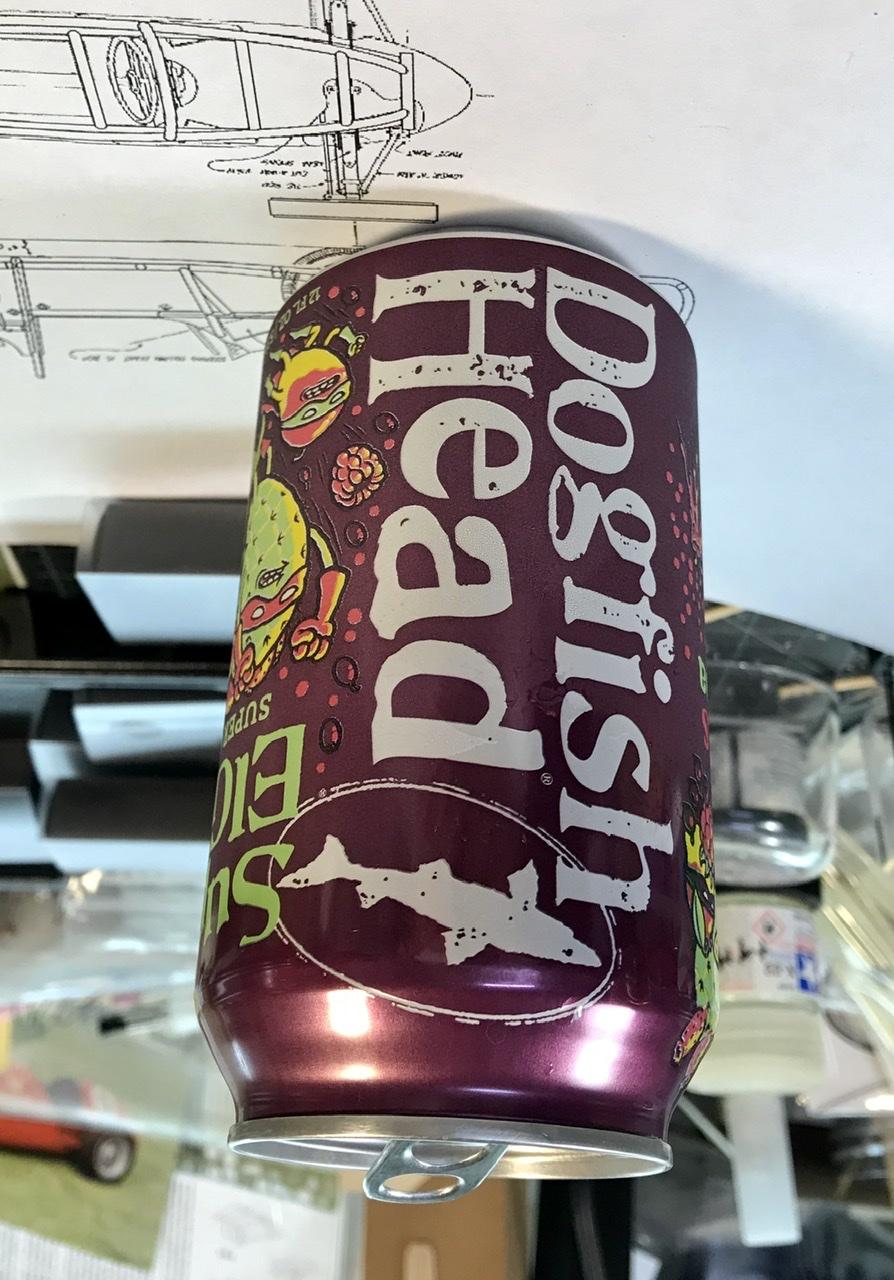
Craft hobby craft beer
-
Cooper barn find
absmiami replied to absmiami's topic in WIP: Other Racing: Road Racing, Land Speed Racers
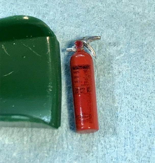
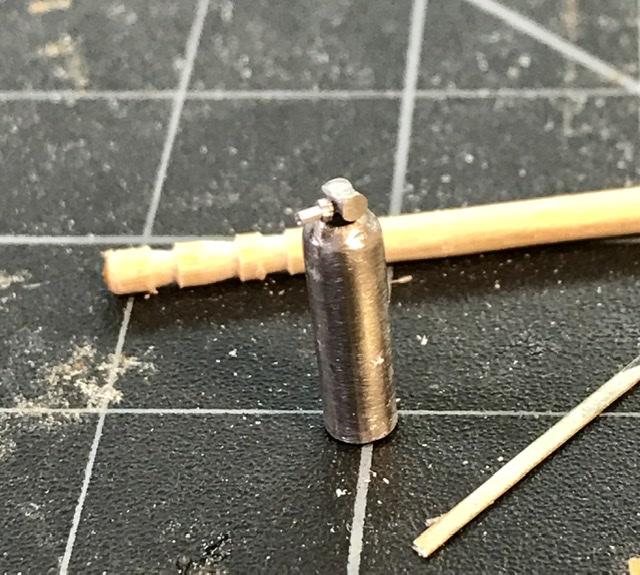
The bottle is from a white metal stash from the deepest recesses of my accessory drawer. Thought I would never use it. It was almos the exact size - within .020 In diameter
-
Cooper barn find
absmiami replied to absmiami's topic in WIP: Other Racing: Road Racing, Land Speed Racers
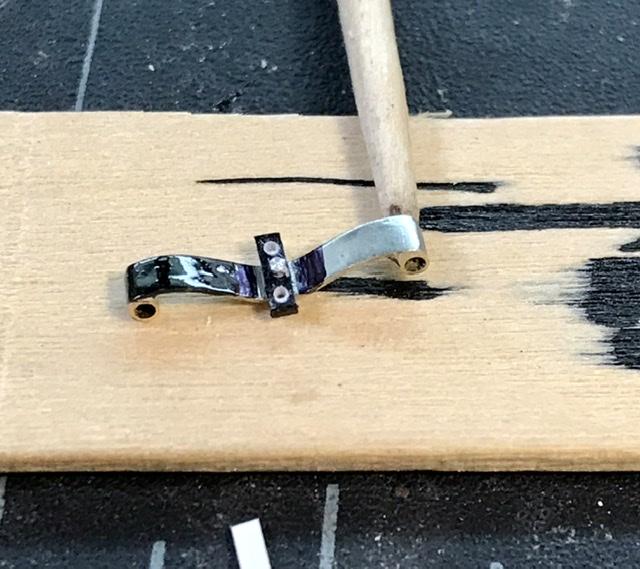
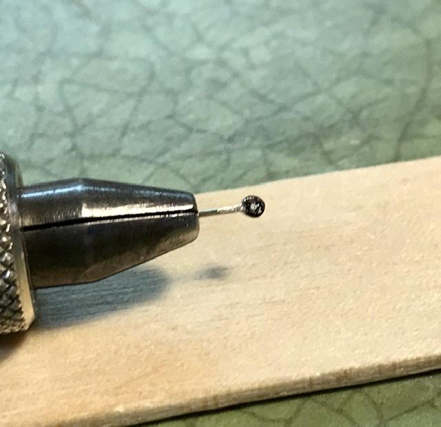
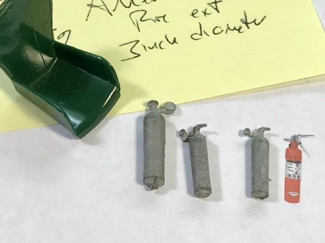
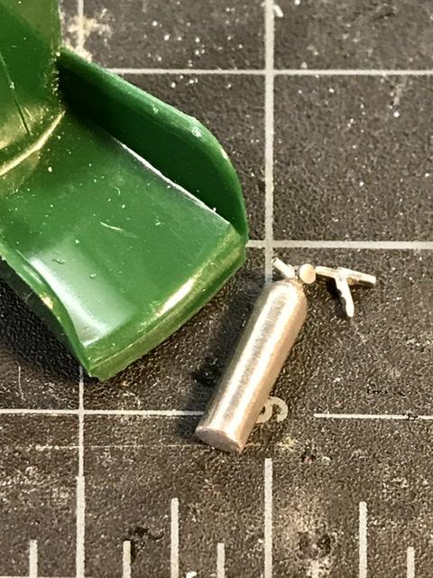
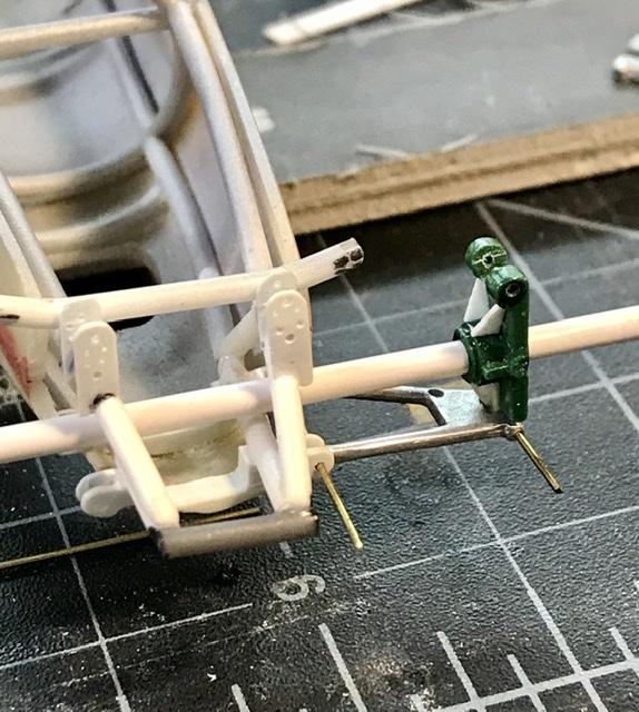
Working on the fire bottle that sits in front of the seat the restored car has an Amerex extinguisher the bottle is for sale - with everything else - on eBay so I printed the image and ran some decal paper thru my printer and brushed some Tamiya clear over the image. - it’s low res but it will look good on the bottle the handle is some nickel silver bar - folded over and bent to shape -
Cooper barn find
absmiami replied to absmiami's topic in WIP: Other Racing: Road Racing, Land Speed Racers
Working on the fire bottle that sits in front of the seat the restored car has an Amerex extinguisher the bottle is for sale - with everything else - on eBay so I printed the image and ran some decal paper thru my printer and brushed some Tamiya clear over the image. - it’s low res but it will look good on the bottle the handle is some nickel silver bar - folded over and bent to shape
-
Cooper barn find
absmiami replied to absmiami's topic in WIP: Other Racing: Road Racing, Land Speed Racers
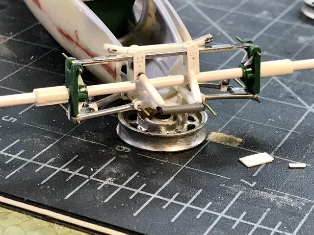
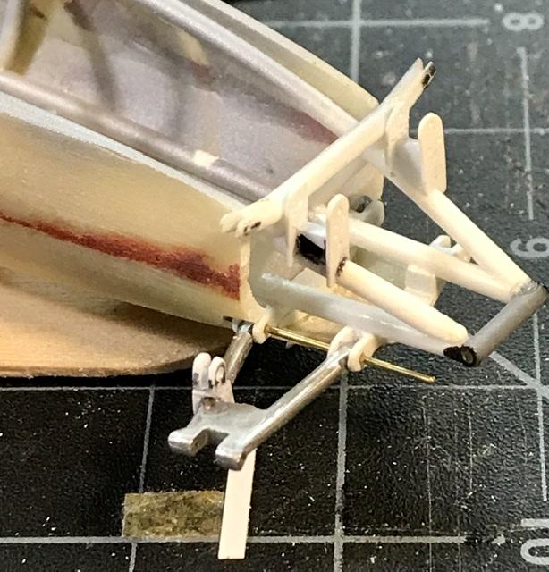
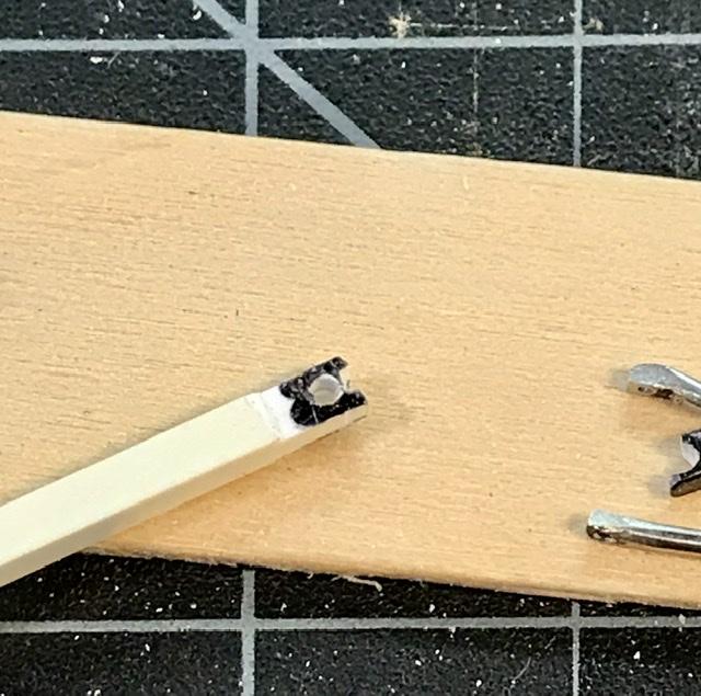
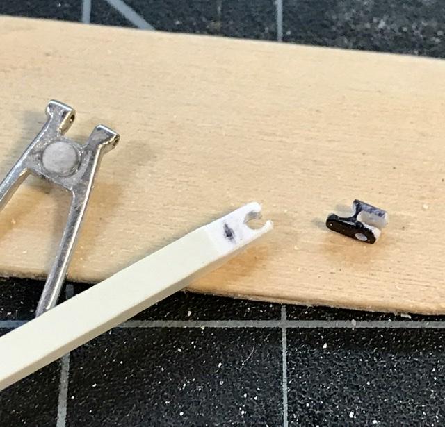
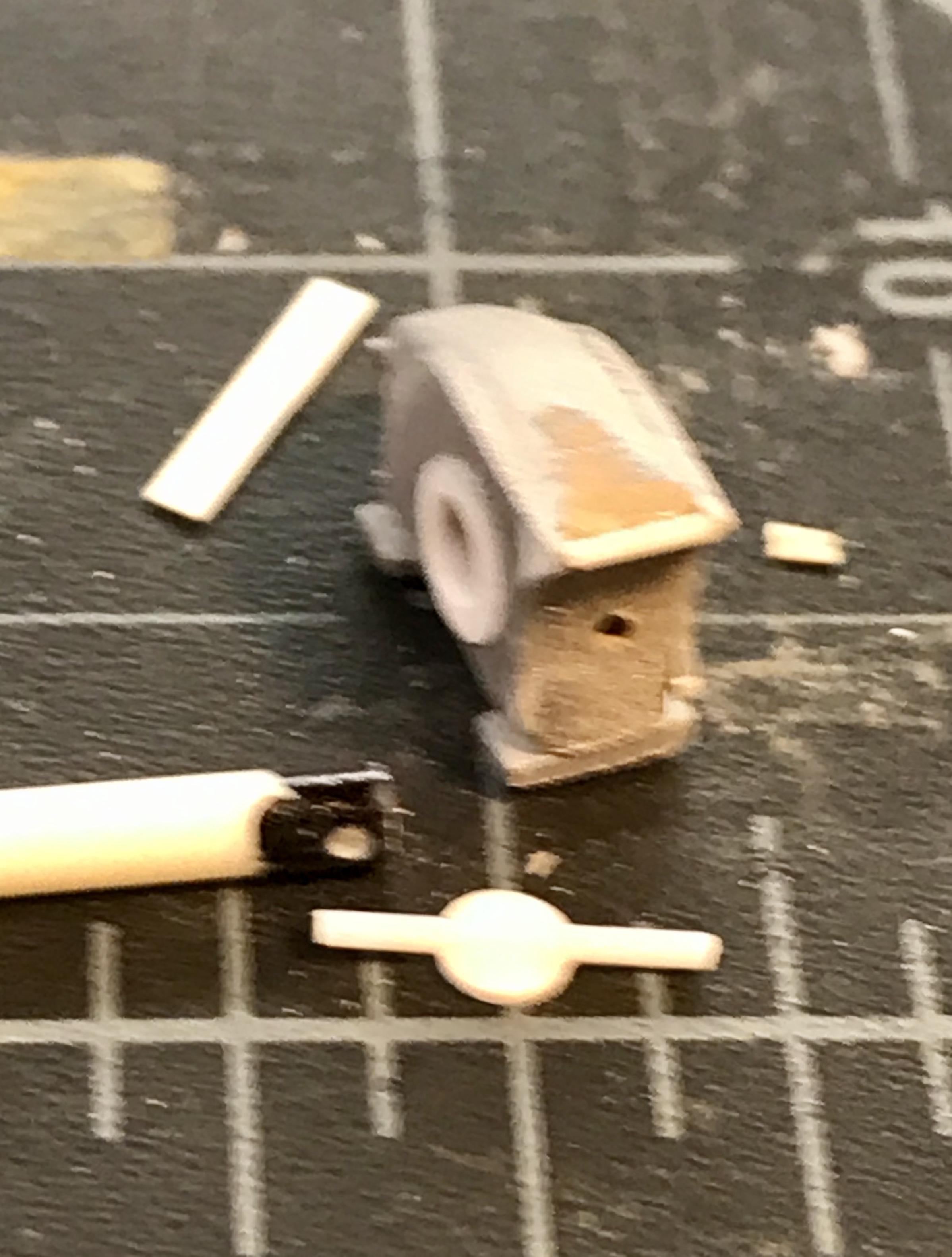
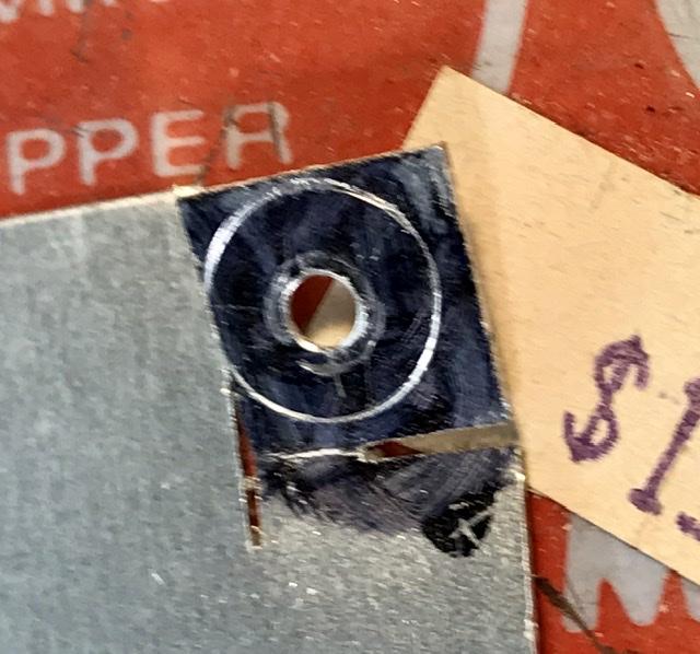
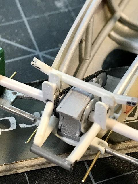
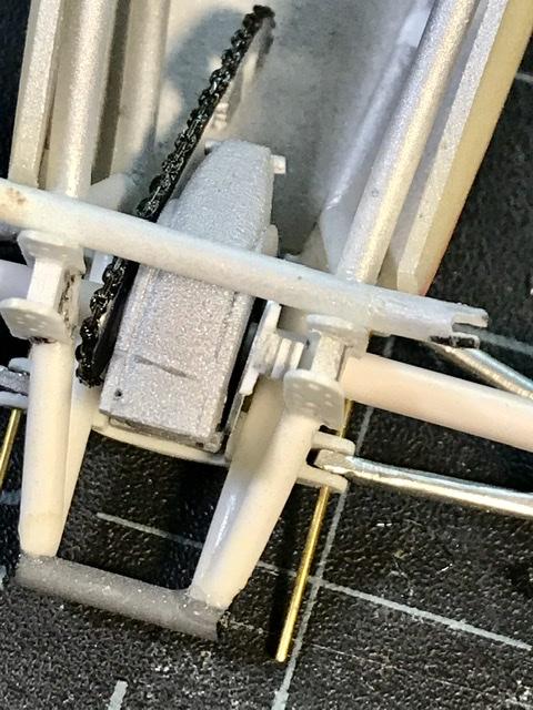
As the frame members converge- there is barely enough room for the chain drive and rear brake - which hugs the right side of the transaxle . The mark 9 Cooper was one of the first race cars to rely on a single central mounted brake disc. Made from 16th aluminum- cut, filed and sanded and if you look carefully - there is a brake caliper made from some bits of evergreen plastic bar
-
Cooper barn find
absmiami replied to absmiami's topic in WIP: Other Racing: Road Racing, Land Speed Racers
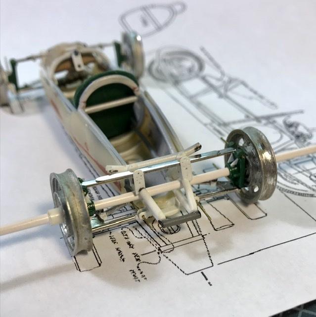
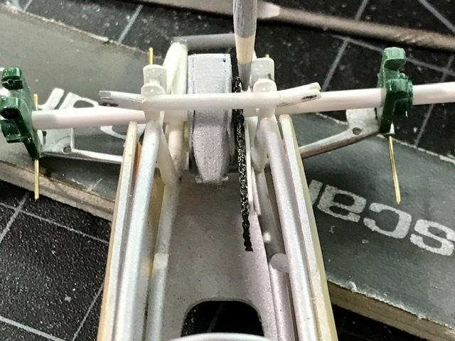
the transaxle squeezes into the frame the half shafts will run thru the frame and the transaxle. The tube is used at this stage as a guide
-
Cooper barn find
absmiami replied to absmiami's topic in WIP: Other Racing: Road Racing, Land Speed Racers
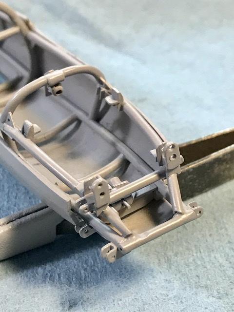
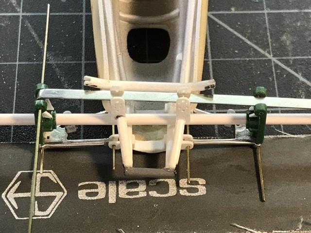
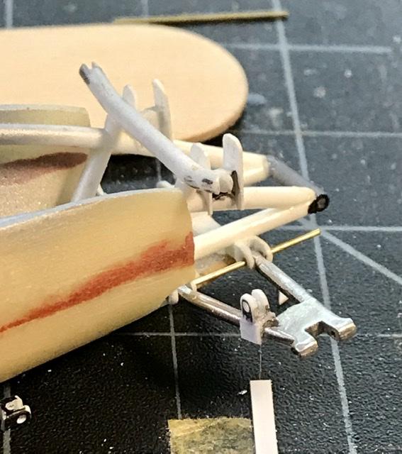
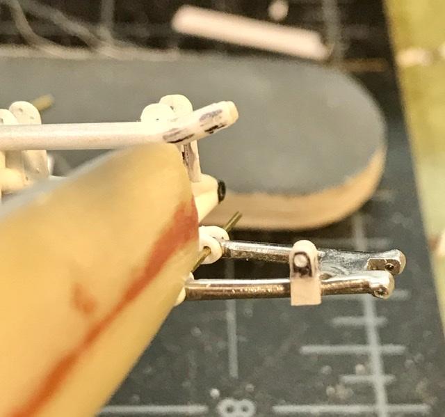
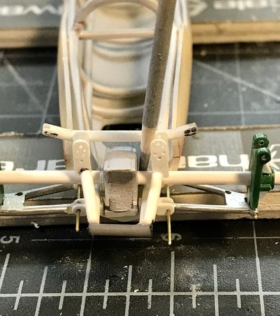
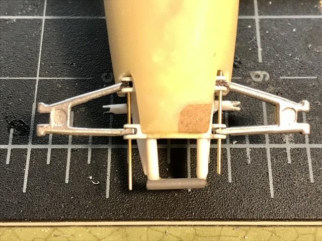
Some more mock up shots to check alignment of the uprights