absmiami
-
Posts
4,780 -
Joined
-
Last visited
Content Type
Profiles
Forums
Events
Gallery
Everything posted by absmiami
-
Cooper barn find
absmiami replied to absmiami's topic in WIP: Other Racing: Road Racing, Land Speed Racers
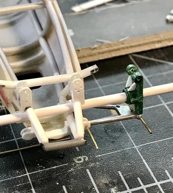
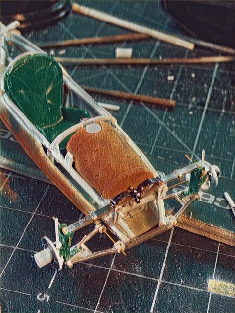
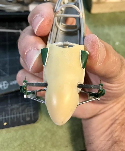
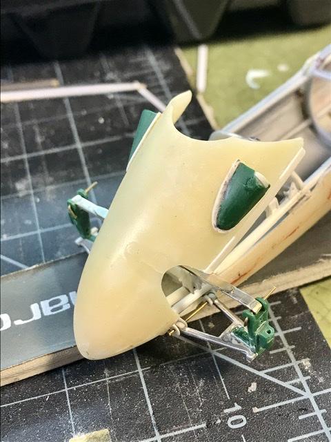
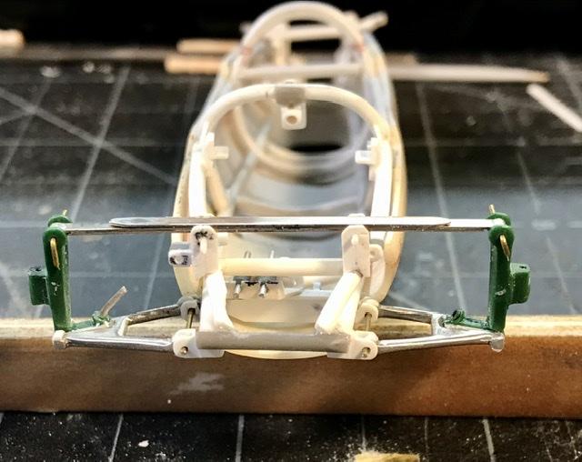
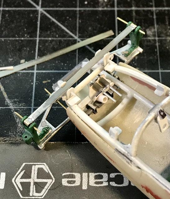
Some more mock up shots to check alignment of the uprights
-
Cooper barn find
absmiami replied to absmiami's topic in WIP: Other Racing: Road Racing, Land Speed Racers
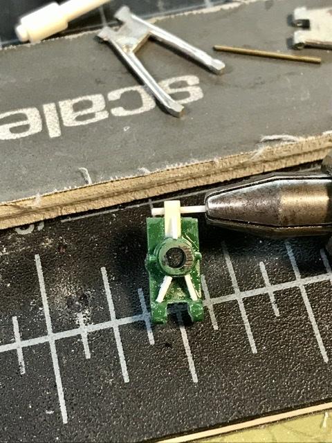
Have to start by correcting an error that I made two years ago plugging a bolt hole in one of the rear uprights - and then drilling a new hole - the new hole hopefully not crooked... the new hole does the trick - as the plastic tube Guide now passes through the upright parallel to the trailing suspension arm ... the susp arms are white metal - from the herb seeks kit ... as per the front susp ...
-
Fiat 131 Abarth
absmiami replied to afx's topic in WIP: Other Racing: Road Racing, Land Speed Racers
Imagine Miami with the clubs closed .... -
Fiat 131 Abarth
absmiami replied to afx's topic in WIP: Other Racing: Road Racing, Land Speed Racers
Very very klean ..... just thinking about Ireland with pubs closed .... -
Cooper barn find
absmiami replied to absmiami's topic in WIP: Other Racing: Road Racing, Land Speed Racers
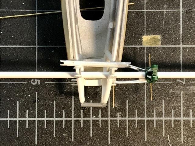
Now back to the rear suspension - which I had begun to work on over two years ago - somewhere on page 3 ... -
Cooper barn find
absmiami replied to absmiami's topic in WIP: Other Racing: Road Racing, Land Speed Racers
And a shock absorber - made from 16th alu tube with a nickel plunger
-
Cooper barn find
absmiami replied to absmiami's topic in WIP: Other Racing: Road Racing, Land Speed Racers
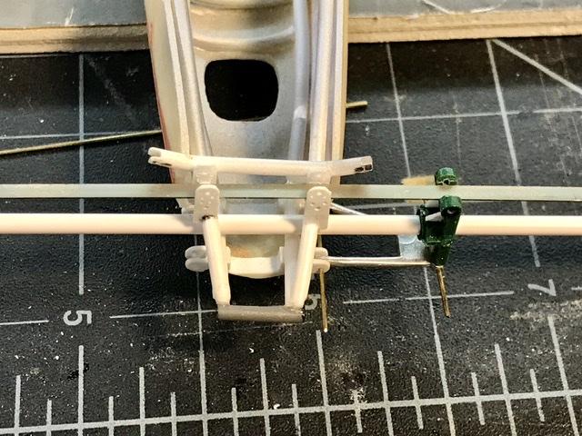
The section of the frame that sites the leaf spring gets two tabs that site the sway bar on top of the spring - liquid glued
-
Cooper barn find
absmiami replied to absmiami's topic in WIP: Other Racing: Road Racing, Land Speed Racers
In the engine bay. The right side brace interferes with the linkage to the fear box i noticed that at least some of these cars were made without the brace - so out it comes ....
-
Cooper barn find
absmiami replied to absmiami's topic in WIP: Other Racing: Road Racing, Land Speed Racers
Department of Corrections the frame cross member in the foot well is in the wrong place - too close to the location of the pedals - sure to break some ankles if the cooper hit something... so I removed it with a small cutting burr and liquid glued its replacement about a quarter inch farther back now I can make and locate the pedals ...
-
Cooper barn find
absmiami replied to absmiami's topic in WIP: Other Racing: Road Racing, Land Speed Racers
Some more ...
-
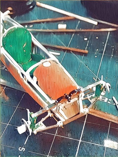
Cooper barn find
absmiami replied to absmiami's topic in WIP: Other Racing: Road Racing, Land Speed Racers
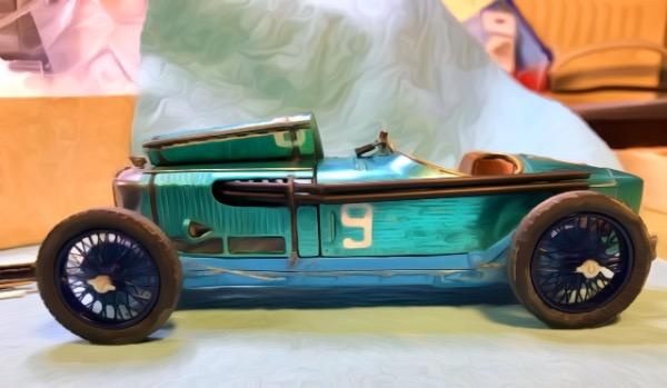
And thanks gramps ... previous photo run through the BeCasso app ...
-
Cooper barn find
absmiami replied to absmiami's topic in WIP: Other Racing: Road Racing, Land Speed Racers
And thanks gramps ... -
Cooper barn find
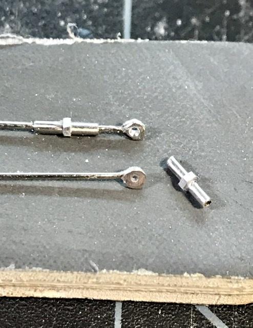
absmiami replied to absmiami's topic in WIP: Other Racing: Road Racing, Land Speed Racers
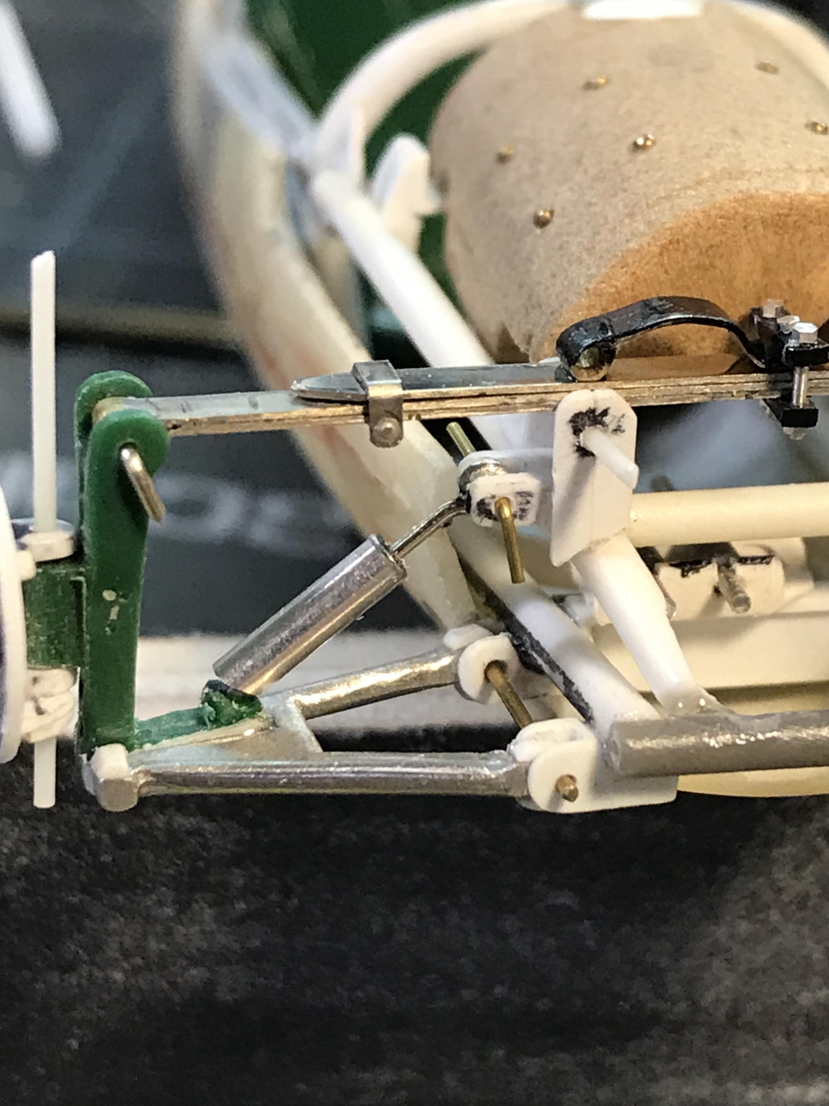
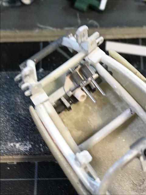
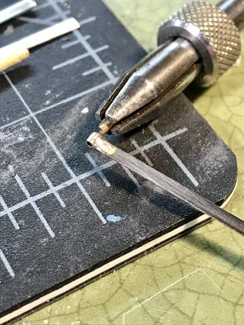
RC. Thanks I always conspire to be a perspiration to the forum Tie rod components nickel tube about .034 With a stray rb motion nut nickel rod .020 the rod end is bent w pliers to form then filled with solder and then drilled per the link to the shifter will add a couple more nuts when assembling
-
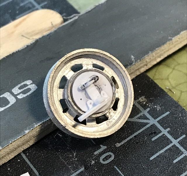
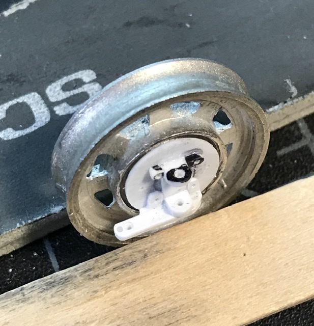
Cooper barn find
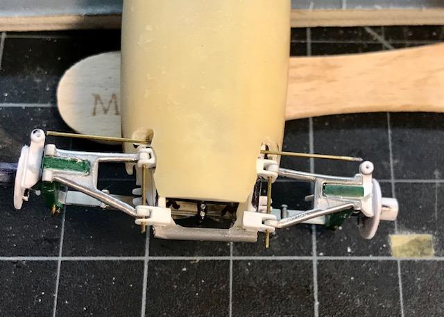
absmiami replied to absmiami's topic in WIP: Other Racing: Road Racing, Land Speed Racers
so the right wheel backing plate/hub assembly now has a friend for the left wheel ... they are attached to the spindle to check fit and operation …. the fourth picture has a brass rod in place to check the run of the tie rod and its relationship with the steering arms next is a beer run then tie rod assembly - then some work on the wheels and then some work on the pedals ….
-
Cooper barn find
absmiami replied to absmiami's topic in WIP: Other Racing: Road Racing, Land Speed Racers
I haven’t gotten this much done in one weekend in years ... my workshop is sick of seeing me ... ... and my bench is a disaster again ... -
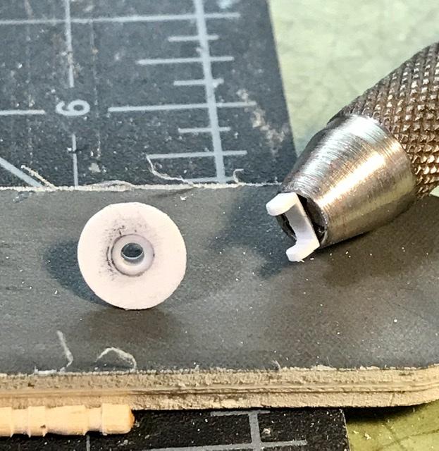
Cooper barn find
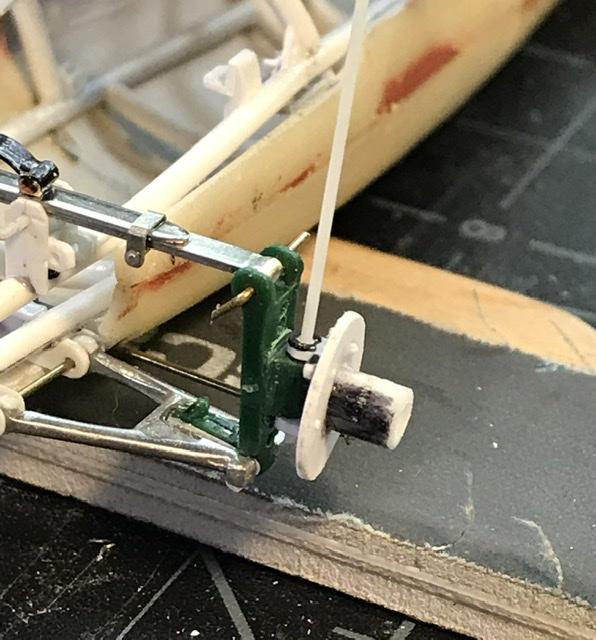
absmiami replied to absmiami's topic in WIP: Other Racing: Road Racing, Land Speed Racers
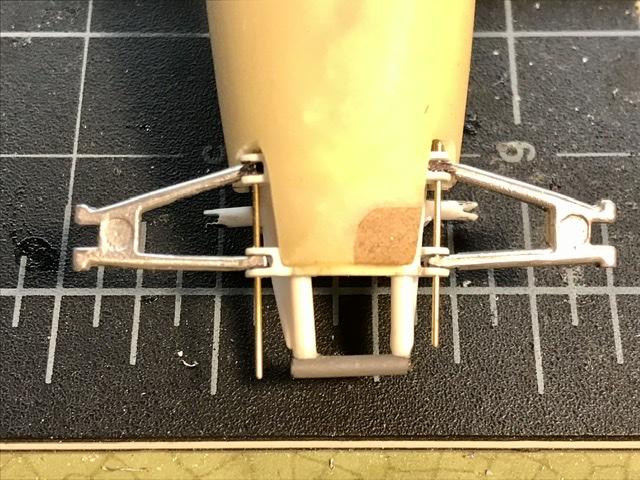
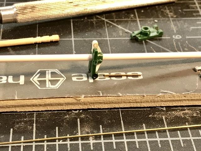
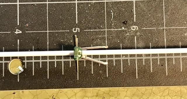
So far so good ... the hub carrier is held to the upright and can pivot on the pin - which at this point is simply a section of .025 evergreen rod next I’ll make the assembly for the right wheel and see if everything points in the right direction
-
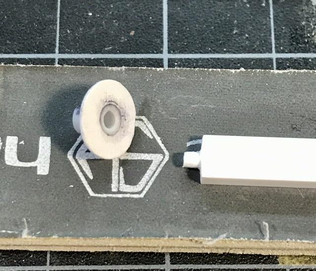
Cooper barn find
absmiami replied to absmiami's topic in WIP: Other Racing: Road Racing, Land Speed Racers
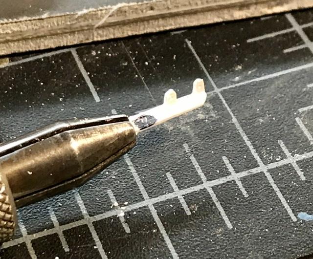
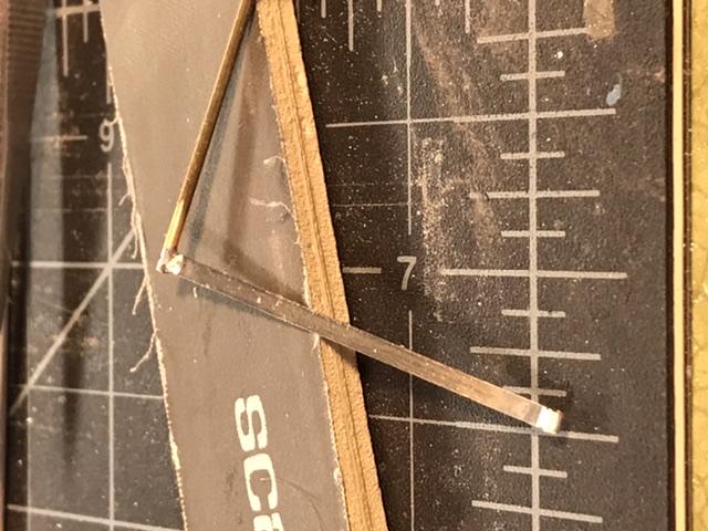
Evergreen sheet, bar, tube files, sanding sticks and some real small holes for bolts the steering arm is filed from.080 L shape evergreen with a second piece of .015 by .060 bar to reinforce the steering arm the arm is then glued w Tamiya liquid glue to the backing plate this glue was used for the whole assembly I like the way that this glue fuses the parts for a strong bond
-
Cooper barn find
absmiami replied to absmiami's topic in WIP: Other Racing: Road Racing, Land Speed Racers
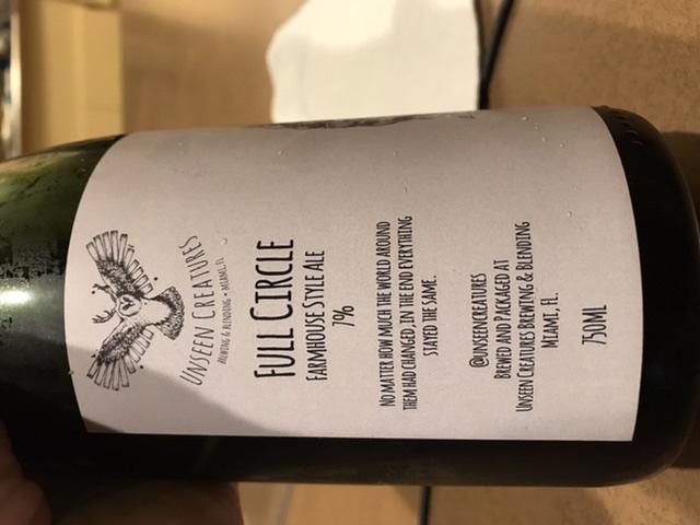
Thanks The bottle has a removable vinyl (?) adhesive label maybe I can is it for masking material ?? you never know ... or I could make a scale Unseen Creatures beer truck .... Hmmmm ....
-
Cooper barn find
absmiami replied to absmiami's topic in WIP: Other Racing: Road Racing, Land Speed Racers
Next some work on the wheels and the backing plates and the steering kingpins ... that beer was good ...
-
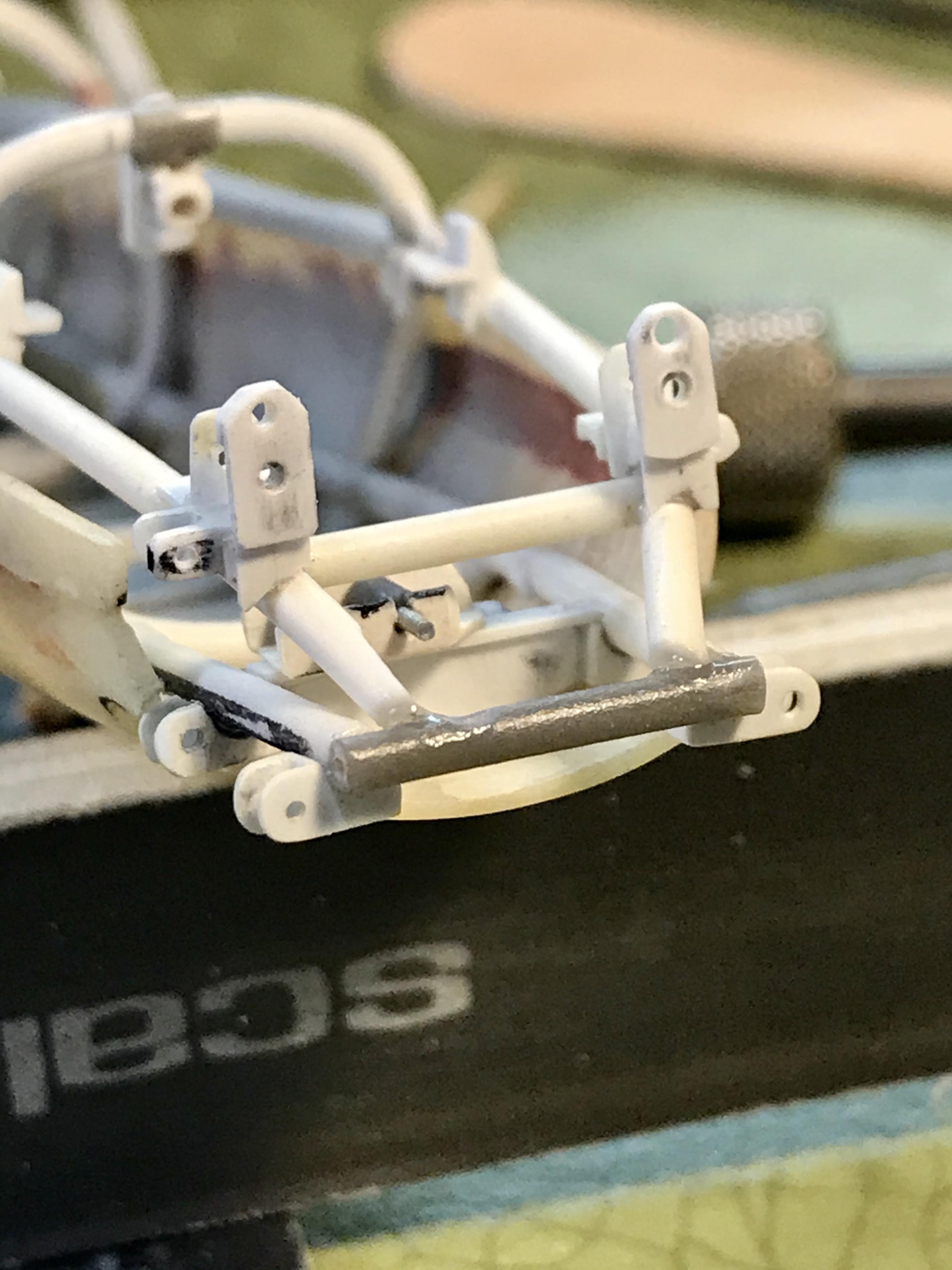
Cooper barn find
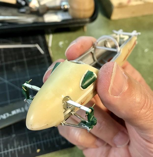
absmiami replied to absmiami's topic in WIP: Other Racing: Road Racing, Land Speed Racers
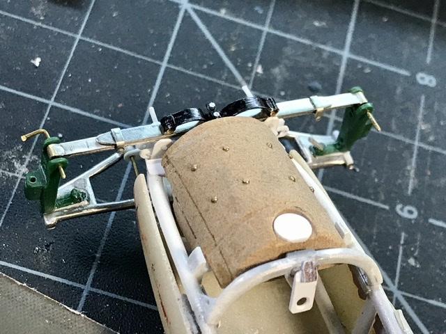
All of the cooper suspensions- til 1960 - used a sway bar or anti roll bar that perched on top of the leaf spring ... that’s the black curly Q thing above the spring the center locating bracket is made from evergreen bar - .020 by .040 - and RB motion aluminum .025 bolts n nuts ... and there is a shackle bent from some nickel bar on either side of the spring ...
-
Cooper barn find
absmiami replied to absmiami's topic in WIP: Other Racing: Road Racing, Land Speed Racers
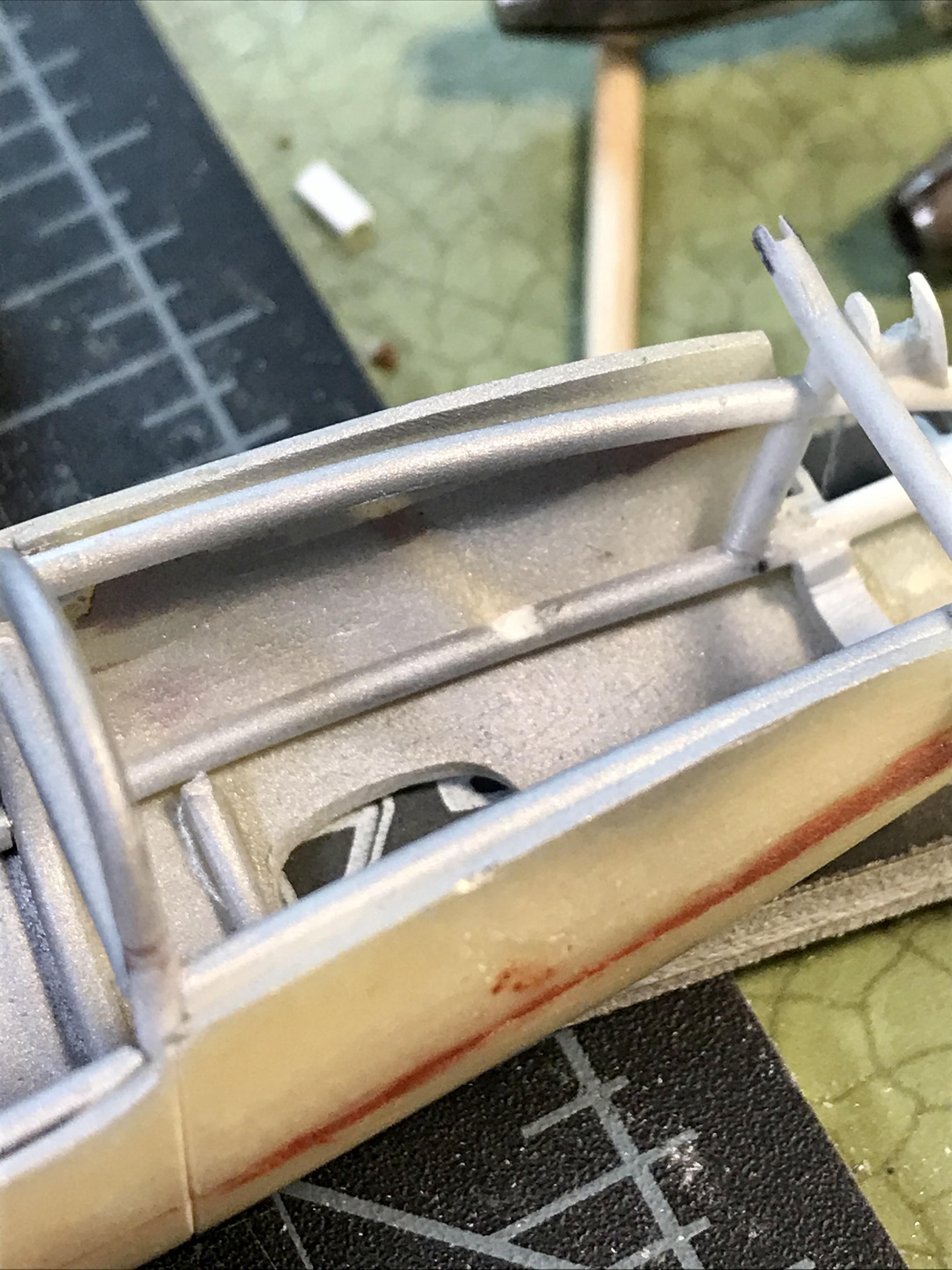
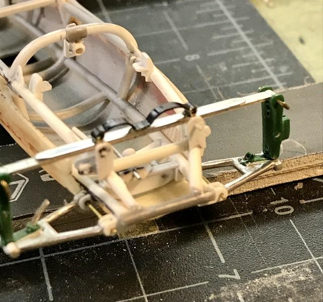
Once the spring leafs - 3 - were soldered and the opening in the nose was corrected it was time to add some hardware to the lead spring ...
-
Cooper barn find
absmiami replied to absmiami's topic in WIP: Other Racing: Road Racing, Land Speed Racers
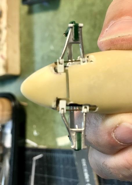
Soldering on the flammable balsa board again don’t try this at home once the spring is pinned to the uprights I realized that I had to enlarge the openings in the nose but that’s easier than reducing the size of the cut out - right?
-
Cooper barn find
absmiami replied to absmiami's topic in WIP: Other Racing: Road Racing, Land Speed Racers
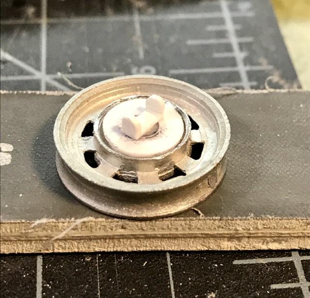
Unseen creatures is a new craft brewery in south miami very good might as well support the local brewers while things are .... as they are ..... the next few parts are in nickel silver measuring cutting filing sanding and then soldering
-
Cooper barn find
absmiami replied to absmiami's topic in WIP: Other Racing: Road Racing, Land Speed Racers
-
Cooper barn find
absmiami replied to absmiami's topic in WIP: Other Racing: Road Racing, Land Speed Racers
time for a beer run not much open here - but the local breweries are still - as is my business - which I appreciate [both...]