absmiami
-
Posts
4,780 -
Joined
-
Last visited
Content Type
Profiles
Forums
Events
Gallery
Everything posted by absmiami
-
Mmmm .... exotics .....

-
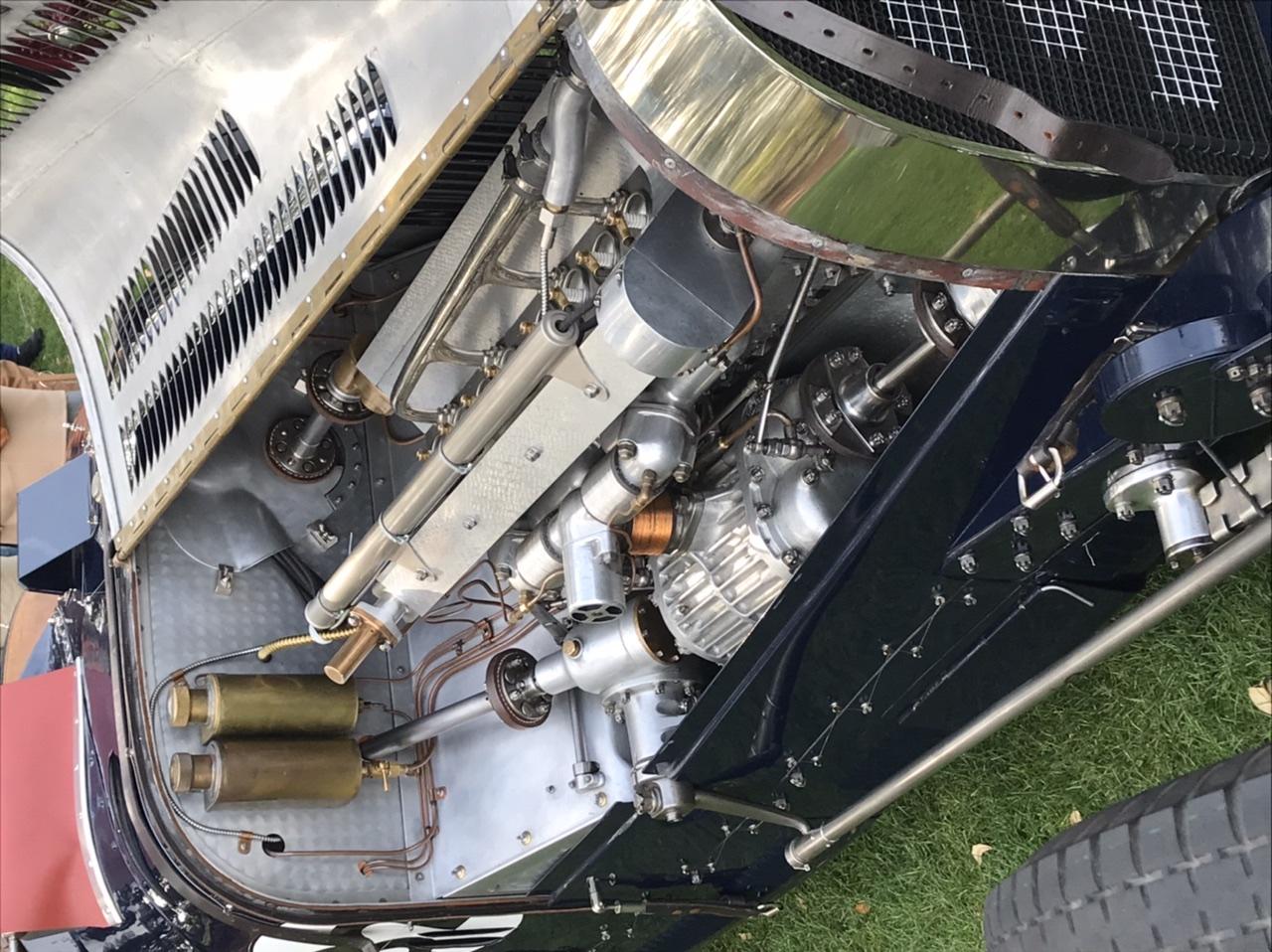
Off to Amelia island never know .... might see some .... old racing engines ....
-
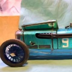
Cooper barn find
absmiami replied to absmiami's topic in WIP: Other Racing: Road Racing, Land Speed Racers
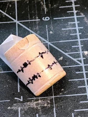
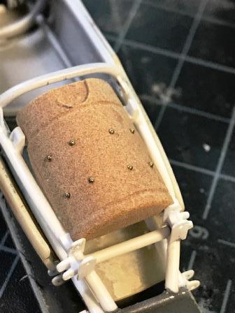
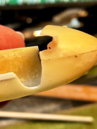
the alu fuel tank is perched above the driver's legs made from renshape - I'm adding the rivets before painting rivet holes are marked on some parafilm - 3M - just so I can re-mark - I'm just eyeballing the placement of holes - without placing marks in the surface of the tank the fuel tank cap sits in the depressed semi circle - and is accessible in front of the dash hoop ...
-
Cooper barn find
absmiami replied to absmiami's topic in WIP: Other Racing: Road Racing, Land Speed Racers
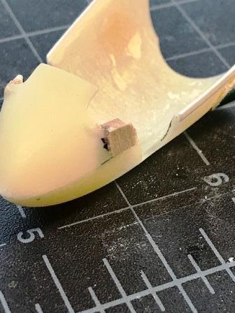
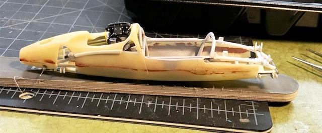
there's lots going on in front of the driving compartment so I'm hinging the forward clip - but I've got to add a small section of renshape to the lower corners of the clip for this purpose the scrap renshape plug is glued on with CA - which will give it a chemical bond with the adjoining resin - and then sanded with sanding sticks and files ... the parts have to be precise because they hinge right next to the pick-ups for the front suspension arms ….. this will be delicate - I'll have to be careful with this hinge I'll reinforce them with small metal rings ….
-
Cooper barn find
absmiami replied to absmiami's topic in WIP: Other Racing: Road Racing, Land Speed Racers
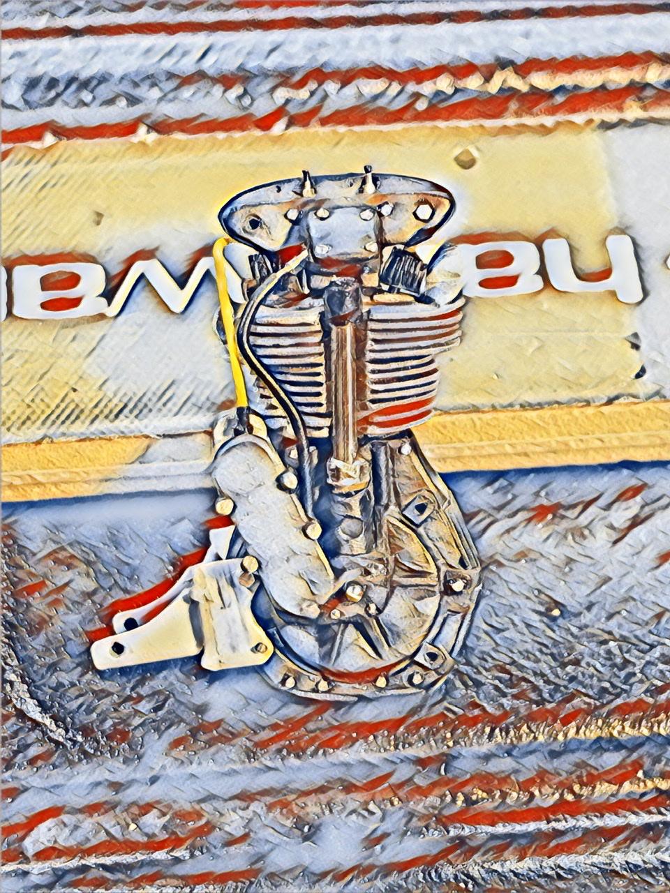
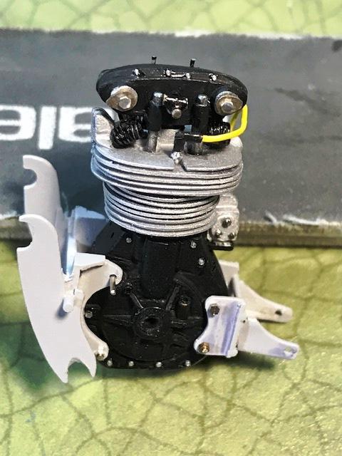
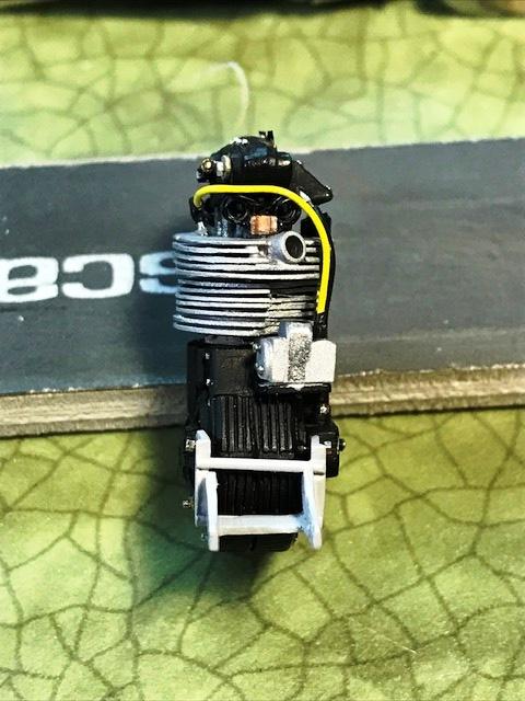
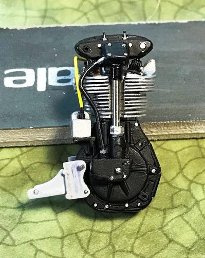
the Norton engine is back from the engine builder - the carbureter is still at the carb resto shop ... the engine is in for a test fit so I can trim and fit the engine cover - almost done it will pivot on a nickel silver rod - think it's .015
-
Some more “art” ...
-
Oh no you really want the workbench. Story? maybe after a beer or two ......
-
the front engine brace is now attached with some .013 nickel rod and RB bolts and the timing chain cover is glued on to the crank case and the side of the plug distributor - if there is only one plug - is this a "distributor"? the carb needs an intake trumpet and some fuel wires before it is attached ... there are at least 2 oil lines running into and out of the crank case - possibly more - based upon photos of the crank case that I glommed from the 'net ... still figuring that out ...
-
got the cam box on - with the valves and valve springs sitting on top of the head and barrel. and the rear engine brace is attached. The shaft running down to (up to?) crank case is the only polished part on the engine the spark plug is fr RB Motion, as are the boots for the plug and the distributor the plug wire dimension is .016 - which is perhaps slightly over-sized - .013 would have been more precise - but I did not have any yellow .013 plug wire - Detail Master makes them - and I didn't want to stop the build to order the correct size for an engine with just one spark plug ! have to replace a couple of engine bolts that went AWOL ...
-
whilst pondering the Ferrari I got some paint onto the Norton Cooper engine flat, dull, and flat ... the "head and barrel" was painted with alclad fl aluminum and the crank case was painted with Tamiya flat black then added the bolt detail - mostly RB Motion - sizes .015 and .017 the first picture has a vertical shaft housing that runs from the crank case up to the cam box - made from 1.2 Mil nickel silver rod with some added detail top and bottom - will replace the white metal casting that is included in the Deeks kit - it's a very good part - but I modified it and it ended up to be to short for my needs … once I paint and attach the engine brackets I can attach the cam box and valve springs, and some other parts ….. its finally starting to look like an engine - but one that clearly has an 75 year old design …...
-
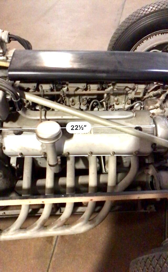
Both the 166 and the 212 had the Colombo small displacement V12 learning how to use a measurement app on my camera phone .... this shows the length of the cam cover on the small displacement 12 ....
-
Nothing yet on simeone website but since mistakes on the internet never get corrected - I think the Ferrari in question is a 166 F2 and not the 212 but the differences are slight I’ll post some more pics later this week .....
-
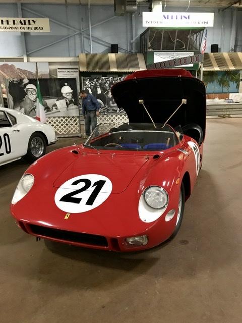
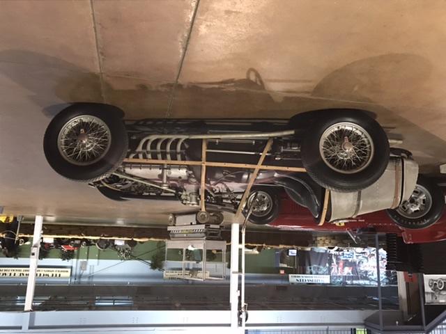
So while I’m wandering around Pennsylvania I made my annual trip trek to the simeone museum in philly and I happened upon the 1963 lemans winner ...... just to enjoy the contrast .....
-
Or just flip my phone around ???
-
Guess things are a bit upside down right now really need to learn how to use my phone ...
-
Thanks for the post Good to hear from you wish I wasn’t 1500 miles away fr my workshop will try this when I’m back hope the photo fr my trip to the simeone loads right side up .....
-
Saturday at the simeone museum in philly. Amazing display of rare Ferraris owned by chinetti jr the bardahl Indy Ferrari the lemans winning Ferrari 250 p a gp Ferrari F2 without the body panels. I think a 212 GP and several others saw staff set up the cars for display today wetinthepants some photos next week go! go!
-
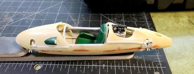
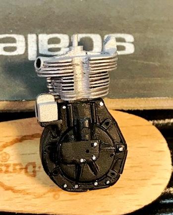
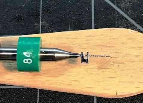
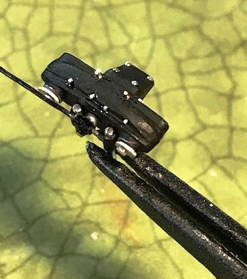
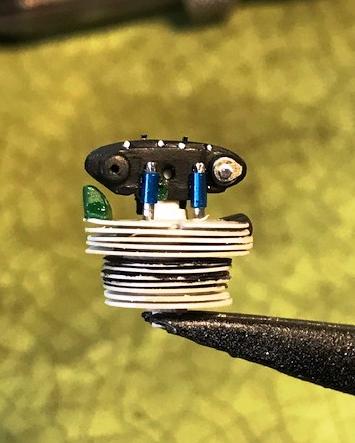
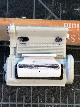
love that printed Cord dash …. the exposed valve springs which sit on top of the "head and Barrel" - that's what it's called in the parts catalog on line for www.worksracing.co.uk - made from .009 steel wire - wound around a 2-56 bolt and painted with a sharpie the springs are glued to a small clip-like part made from some evergreen with size 84 holes drilled for the stems of the valves per this same online catalog - the top of the engine - which I called a rocker casting - is more properly called a cam box ... not shown in the photos - there will be two more springs perched on the other side of the head and barrel ... even though the springs are very small - everything will be a tight fit and need part adjustments when assembled ... soon - I might actually start to paint some things ...
-
almost forgot.... don't try this at home balsa wood is indeed combustible ...
-
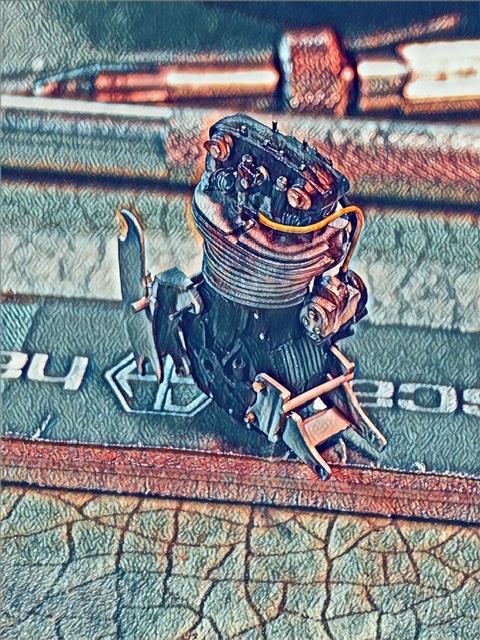
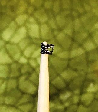
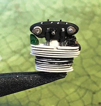
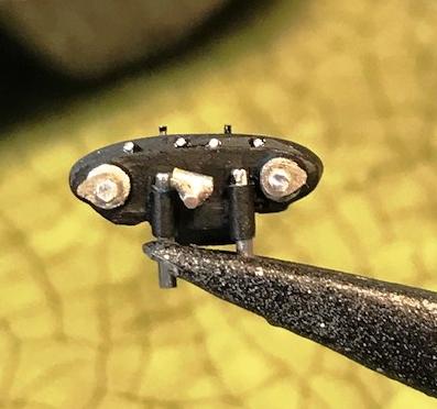
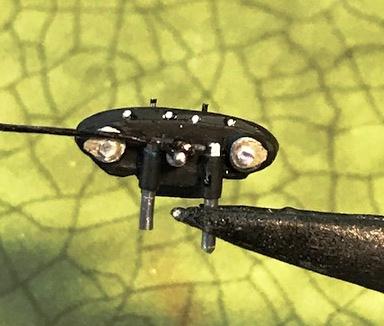
the tach line runs into the rocker housing in an elbow fitting made from .060 mm tubing soldered to a slightly smaller nickel rod - finished with files and sanding sticks and sharpie painted black OK the rocker housing is almost done. in between this housing and the top of the cylinder head are four exposed valve springs - two on each side - tickling the exposed rocker valves running down into the top of the cyl head I've always wanted to build an engine with exposed valve springs …. that's next ….
-
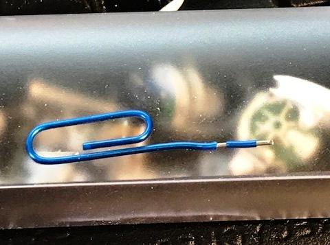
paper clips … big fan - though sometimes I forget how handy they are this one has a vinyl coating - which when painted will appear to be part of the rocker casting with the pins protruding down into the top of the cylinder head ...
-
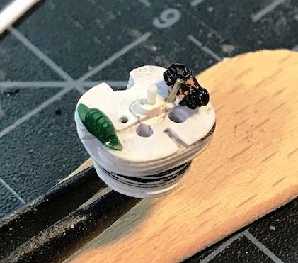
made two pear shaped parts that sit on either side of the rocker housing made of filed nickel silver strip with two RB bolts can't do this w/out the small part holder ...
-
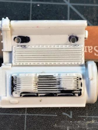
thank you Nitro: As was done on the right side of the crank case - I had to remove the wonderful finned crank case side plate because the 255's - or most of them - used simpler, less elegant plates. Hated to do it …. the AMT kit actually has the correct engine plate and breather on the chrome tree - but it is too short to use with Etzel's correctly dimensioned block …. In place of the fins - removed with a diamond coated rotary sander and an exacto blade - is a plate and breather made from Evergreen strips and bars - liquid glued together, filed and sanded - 4 pieces . to be painted or finished in a dark metal shade - maybe gun metal or darker - not sure this will be surrounded by bolts to be added after I paint the block ...
-
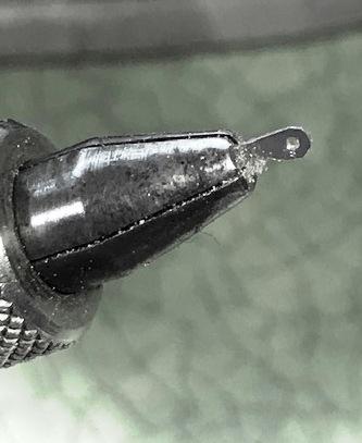
correction - the cap screws are .012 across they might also find there way onto some instrument dashes ….. that's very small
-
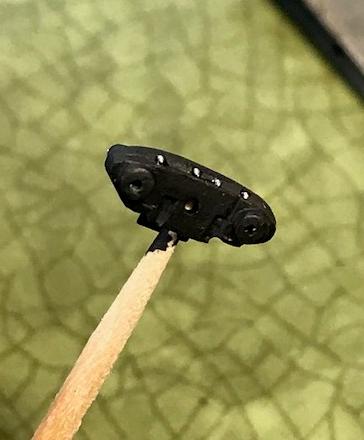
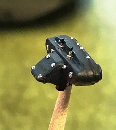
back to the Cooper F III engine briefly ... I had ordered the RB Motion 20th sc DFV valve cover detail set - which includes some absurdly tiny cap screws for the outer rim of the valve covers... they are 0.12 across -- with stem size is about .0010 …. anyone who orders these things and intends to use them needs professional help …. which is why I ordered two sets …. before tackling the DFV engine again I decided to use four of these things on the Cooper Norton cylinder head - which was sawed apart from the engine fin casting - which I discarded - and drilled/modified for bolts screws and other stuff the hardware is from RB Motion, Scale Hardware, and other random sources - the .060 MM screws have been sitting inside a small plastic box for years - can't remember who produced them ... - and brush painted w Floquil steam power black there's more to add - but this is a start - this part sticks up out of the engine bay - completely exposed - so I am adding as much detail as I can the small cap screws need special handling - and magnification installation was done over a black tray - because you WILL drop these things several times - so when the cap screws fall onto a black tray you just tweeze them up and try again …. - if you don't use a black surface the dropped screws will leave the planet - you will never see them again ... in case you were wondering what to do with those neat black plastic sushi trays that you get with your supermarket sushi - you can wash them first - but that is optional …..