RCprofile.JPG.6b95b19b856bf00a3becd6aeaaa48f3b.JPG)
Ian McLaren
-
Posts
1,360 -
Joined
-
Last visited
Content Type
Profiles
Forums
Events
Gallery
Everything posted by Ian McLaren
-
Daniel the chassis looks great, the wheel and tire combo works very well and suits the era. The stance is very believeable and just has that "right" look. Excellent progress!
-
RCprofile.thumb.JPG.1691ea753d0f0897fdc1b2510cf06775.JPG)
full detail 1/16th Gordie Bonin BubbleUp Trans Am Funnycar
Ian McLaren replied to Ian McLaren's topic in WIP: Drag Racing Models
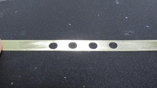
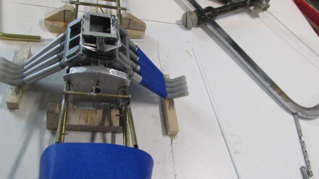
First of the header flanges drilled for the pipes, these serve two purposes, one is to add detail to the headers (even though the LPH1320 has superb details cast in) and second to act as part of assembly jig to set the pipe spacing at the head face while soldering. The head itself can't be used due to the heat involved. The spacing of the holes is 8.8MM C to C, to match the holes in the LPH1320 Keith Black printed heads
- 190 replies
-
- 2
-

-
- scratch built
- brass chassis
- (and 1 more)
-
full detail 1/16th Gordie Bonin BubbleUp Trans Am Funnycar
Ian McLaren replied to Ian McLaren's topic in WIP: Drag Racing Models
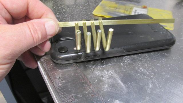
Well it's official, I'm going with scratch built brass headers. Jig is set up and header height and exit positions have been determined. Test bending the first brass pipe to lock down the degrees of bend required to get the proper rear sweep and outward angle of the pipe exits. Should have all eight pipes bent and rough cut to size later today. I want to have the actual header fabrication jigs built in the next couple of days and the headers done by the end of the weekend .
- 190 replies
-
- 1
-
-
- scratch built
- brass chassis
- (and 1 more)
-
’72 Dodge Demon Drag Racer 1/25 scale
Ian McLaren replied to AmericanMuscleFan's topic in WIP: Drag Racing Models
Hello Francis. I hope you are having a good and prosperous summer, we are all patiently awaiting your next update, be well my friend -
full detail 1/16th Gordie Bonin BubbleUp Trans Am Funnycar
Ian McLaren replied to Ian McLaren's topic in WIP: Drag Racing Models
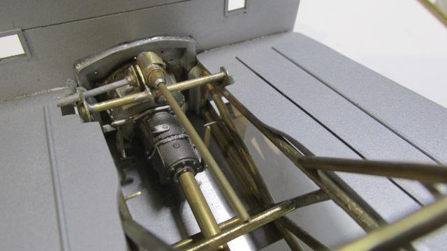
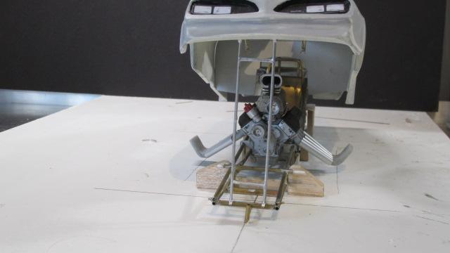
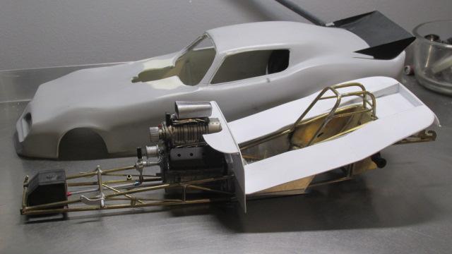
Test fitting the steering and other major drivers compartment assemblies to confirm it all fits together
- 190 replies
-
- 2
-
-
- scratch built
- brass chassis
- (and 1 more)
-
Yup those look just fine, they are a cool addition not often seen!
-
Daniel, I forgot there is a scale difference, you are putting so much detail into the 55, I was regarding it as a 1/16th when doing my calculations, the correct number for what I was aiming for in 1/25 would be .05".
-
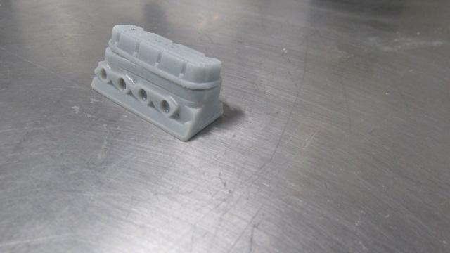
As much as I remember the spacer itself was 1.25" tall and used two .025 reinforced valve cover gaskets, one below and one above. The ones in my model photo are oversized at .092 tall but they tend to warp. To repair that I sand them down to close to where you are I think (080") as per this photo or a scale 1.28". Hard to tell when everything is the same color but to my eye it might have to be a bit shorter. But the .080 I think may be workable.
-
The reason for the thicker spacers on the BBC was with the solid roller camshafts and required spring pressures the rocker arm studs would flex and eventually snap off and the pressured s also played havock with valve lash. Jomar solved both problems with their girdle the studs would support each other through the u-bolts that also locked down the valve adjustment. They made valve adjustment a little more tedious but the reliabilty gains were well worth the extra effort
-
Absolutely a great model, all areas very well done, excellent attention to detail and scale. You should be very proud of this project!
-
Some how it figures it would be you who is the only other guy to put Jomar stud girdle spacers under his BBC valve covers. I have a set for my next build as per the photos below. The car we raced in the early70s, I just love the authenticity you put into your models! I appologise for the huge photo but it was sent to me as one image but does show of the spacers quite well
-
full detail 1/16th Gordie Bonin BubbleUp Trans Am Funnycar
Ian McLaren replied to Ian McLaren's topic in WIP: Drag Racing Models
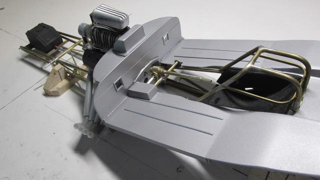
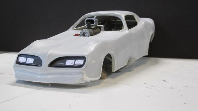
All of the major pieces now fit together including the windshield, after a couple of channel adjustments were made. One more coat of primer and a sanding with 1500 grit will see the body ready for the white base coat.
- 190 replies
-
- 3
-
-
- scratch built
- brass chassis
- (and 1 more)
-
full detail 1/16th Gordie Bonin BubbleUp Trans Am Funnycar
Ian McLaren replied to Ian McLaren's topic in WIP: Drag Racing Models
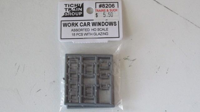
Unsolicited tip for 1/16th modelers. After tearing my hair out trying to get 1/16th scale funnycar fire windows to look right, I found a cheap and exceptionally easy solution at a model railroad shop and they even come with precut glazing and scale out to 4 inches square.
- 190 replies
-
- 3
-
-
- scratch built
- brass chassis
- (and 1 more)
-
full detail 1/16th Gordie Bonin BubbleUp Trans Am Funnycar
Ian McLaren replied to Ian McLaren's topic in WIP: Drag Racing Models
Working on cleaning up the body for the final primer coat so that the base white can be applied, permanent front motor mounts completed,working on decals for the front grills and headlamps these are just test shots on regular paper so that sizing for the final decals can be determined.
- 190 replies
-
- 3
-
-
- scratch built
- brass chassis
- (and 1 more)
-
full detail 1/16th Gordie Bonin BubbleUp Trans Am Funnycar
Ian McLaren replied to Ian McLaren's topic in WIP: Drag Racing Models
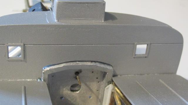
I spent most of yesterday cleaning up and reshaping the windshield retaining flange as well as transfering the new shape to a piece of clear polyester sheet. I also created a transition from the flange to the top of the body tin work right at the front. The windshield fit is pretty good but I will do some additional clean up during the final finishing phase.
- 190 replies
-
- 2
-
-
- scratch built
- brass chassis
- (and 1 more)
-
full detail 1/16th Gordie Bonin BubbleUp Trans Am Funnycar
Ian McLaren replied to Ian McLaren's topic in WIP: Drag Racing Models
Thanks Daniel, yes everything wants to run into everything else, what is a 1/4 inch clearance in real life is virtaully touching in 1/16th. Yes I'm pretty happy with the tin, it was my intention to use the plastic as just a mockup and pattern for brass or aluminum, But in as much as the real car had semi gloss black anodized aluminum there isn't a realy good argument for using either metal to replace the current piece.- 190 replies
-
- 1
-
-
- scratch built
- brass chassis
- (and 1 more)
-
full detail 1/16th Gordie Bonin BubbleUp Trans Am Funnycar
Ian McLaren replied to Ian McLaren's topic in WIP: Drag Racing Models
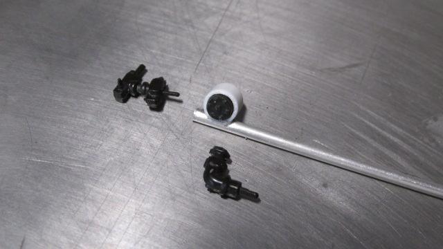
Not a lot has happened lately but some progress, windshield has been templated (tape, then paper and now styrene) and ready to cut the clear part, interiour tin in final template stage and new fuel pump built (Hilborn for now but may switch Enderlie as it is the more likely choice back then, still checking photos)
- 190 replies
-
- 2
-
-
- scratch built
- brass chassis
- (and 1 more)
-
full detail 1/16th Gordie Bonin BubbleUp Trans Am Funnycar
Ian McLaren replied to Ian McLaren's topic in WIP: Drag Racing Models
Thank you John it's all good now and I have made some progress, the next little while should show some substancial changes now that several of the small assemblies have been completed. -
full detail 1/16th Gordie Bonin BubbleUp Trans Am Funnycar
Ian McLaren replied to Ian McLaren's topic in WIP: Drag Racing Models
Thanks Daniel, yes it was and I'm am happy with the enine now. Since then life has kind of out ranked modeling but I have made some small advances.- 190 replies
-
- 1
-
-
- scratch built
- brass chassis
- (and 1 more)
-
full detail 1/16th Gordie Bonin BubbleUp Trans Am Funnycar
Ian McLaren replied to Ian McLaren's topic in WIP: Drag Racing Models
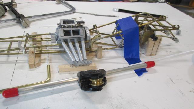
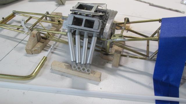
Now with the rear motor plate location set, the power train can start to be positioned and angles set for the coupler shaft.
- 190 replies
-
- 2
-
-
- scratch built
- brass chassis
- (and 1 more)
-
Great progress, wheelie bars (if you can call them that) perfectly period correct, love the wheel color overall and the purple should be a winner. How the hell did you letter the front Firestones?
-
full detail 1/16th Gordie Bonin BubbleUp Trans Am Funnycar
Ian McLaren replied to Ian McLaren's topic in WIP: Drag Racing Models
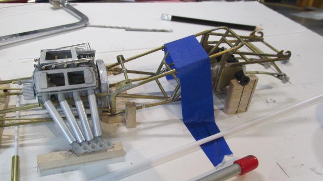
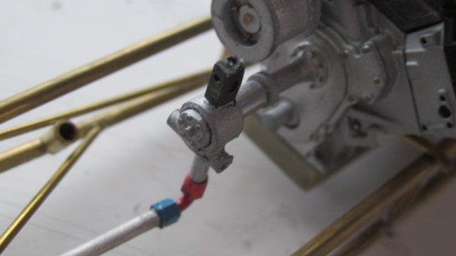
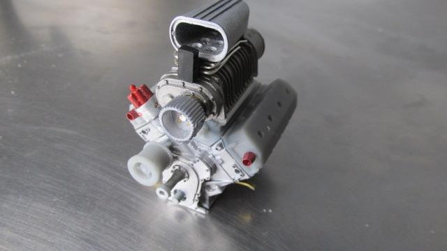
A little more progress, mag finish now on the blower, fuel distribution block for both the hat and port injectors are built and installed as are all of the fuel hard lines. Waiting for fittings before fully plumbing the engine and also working on a larger fuel pump as per the original car. system
- 190 replies
-
- 3
-
-
- scratch built
- brass chassis
- (and 1 more)
-
full detail 1/16th Gordie Bonin BubbleUp Trans Am Funnycar
Ian McLaren replied to Ian McLaren's topic in WIP: Drag Racing Models
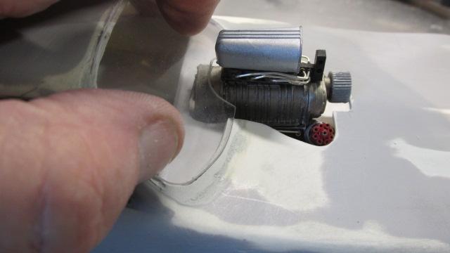
After an involuntary two week modeling layoff I'm back on the Bonin car and I'm focusing on going back and upgrading a lot of what I had already done starting with the engine. New and improved 14-71 Ed Pink style blower still needs the magnesium finish applied but the basic part is much improved, I scrapped the previous injector and redid the plumbing, and the hat is now much closer to scale. Some how I managed to model the entirely wrong magneto for this car, I knew it had a Mallory Super Mag in it and I already had the remote coil in the parts tray. How I put all of the time and effort into building a creditable Vertex mag and then looking at the motor for weeks is beyond me. Thankfully a very knowledgable friend pointed out the error, so the motor now has an all metal Super Mag in place which I put together yesterday, and instantly what has been nagging me about the motor disappeared. Next is the port nozzels and lines and the unique upper plumbing that was on the Bonin car in 78. I'm already much happier with the current result.
- 190 replies
-
- 2
-
-
- scratch built
- brass chassis
- (and 1 more)
-
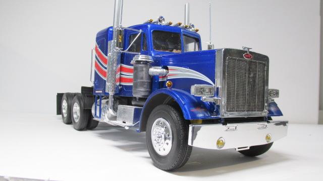
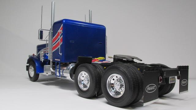
IT"S DONE! Who would have thought this would be my most eventful model built to date. Firstly it was commisioned by my grandson to give to his grandma (other side) as a memorial to her departed husband who actually had just started to build this model (not much more than unboxing it). Secondly this is essentually my first truck model (and I had very little knowledge in this area). This is about as close to an out of the box build as I will every get with the only changes and additions being, all of the clear parts (missing from the box), front drive shaft changed for aluminum tube (original was very badly deformed), additions included trailer uncoupleing lever, air brake hoses, photo etched seat belts (a safety feature), rear license plate bracket and upgrading the exhaust stacks with aluminum tubing ( I just had too) LOL. Paint is out of the can Tamiya Mica Blue overcoated with Tamiya Pearl clear and two coats of Tamiya clear. Lastly I had to take five days off in the middle due to getting a pacemaker. So while I was honoured and pleased to build this for my grandson! ----------- No More Trucks!
- 6 replies
-
- 3
-
-
- out of the box
- first truck
- (and 1 more)
-
A guy is away for a week and you have advance this project greatly, the front suspension and axle a great and I see you've rediscovered the engine turning secret. Your well on your way to another great model. Well done!