
my66s55
-
Posts
1,395 -
Joined
-
Last visited
Content Type
Profiles
Forums
Events
Gallery
Everything posted by my66s55
-
1935 LaSalle convertible coupe - 3d printed at home Aug. 30
my66s55 replied to my66s55's topic in WIP: Model Cars
The improvement of the supports for printing did make the inside come out better with a little effort. -
1935 LaSalle convertible coupe - 3d printed at home Aug. 30
my66s55 replied to my66s55's topic in WIP: Model Cars
This is it's current condition after going through the surface finishing. It still needs a little more work. -
1935 LaSalle convertible coupe - 3d printed at home Aug. 30
my66s55 replied to my66s55's topic in WIP: Model Cars
The body is made up of 3 sections. I'll start with the rear from the door jams back. The first time I printed it, it was made from five separate prints and the rear fenders were separate. Then, the slicing software was upgraded and the support improved so that it could easily be done in one print. These are some print in process. -
1935 LaSalle convertible coupe - 3d printed at home Aug. 30
my66s55 replied to my66s55's topic in WIP: Model Cars
I don't know how many more parts I have to print to complete this project. I say that because its always changing. Here is an example. The first pic is the wheel printed on the fdm printer. There are three pieces so there are three prints required to get the best result. then of coarse, you have to do the surface smoothing. The second pic is the same wheel printed on the high def dlp printer. What you see is exactly as it came from the printer except that I put a light coat of primer on to make it visible for detail. -
3D printing growing as we speak
my66s55 replied to bbowser's topic in General Automotive Talk (Trucks and Cars)
Nothing new. This type thing has been going on around the world for years. Same type products, different city, different show. -
1935 LaSalle convertible coupe - 3d printed at home Aug. 30
my66s55 replied to my66s55's topic in WIP: Model Cars
The stl. files are mirrored and the process is repeated. Next, they go thru the same finishing process shown in an above post. A center connecting piece is then created and the fenders assembled. The final product: -
1935 LaSalle convertible coupe - 3d printed at home Aug. 30
my66s55 replied to my66s55's topic in WIP: Model Cars
The inner half of the drivers side. And the 1st pic is the section from the inner fender to the hood. -
1935 LaSalle convertible coupe - 3d printed at home Aug. 30
my66s55 replied to my66s55's topic in WIP: Model Cars
As I mentioned in my first post here, I attempted to scratch build this car in a coupe. I was stopped dead when I couldn't get the front fenders to even come close to looking the same. 3d printing fixed that. Here are the front fenders. Note that they are in 3 parts and solid. That's the way I could get the most accurate print. I used a motor tool to hollow them out and then ca glued them together. The outer part of the drivers side fender. -
50
-
1935 LaSalle convertible coupe - 3d printed at home Aug. 30
my66s55 replied to my66s55's topic in WIP: Model Cars
That's because the engine parts could be printed flat on the printer bed and didn't require any support material. -
1935 LaSalle convertible coupe - 3d printed at home Aug. 30
my66s55 replied to my66s55's topic in WIP: Model Cars
Then, the finished product assembled and resin cast. -
1935 LaSalle convertible coupe - 3d printed at home Aug. 30
my66s55 replied to my66s55's topic in WIP: Model Cars
Then the 4 prints plus the dead and front plate . -
1935 LaSalle convertible coupe - 3d printed at home Aug. 30
my66s55 replied to my66s55's topic in WIP: Model Cars
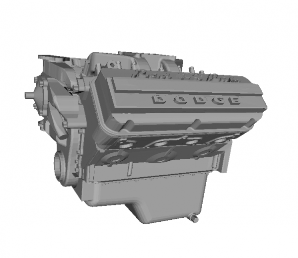
Yes, it is Dominik. It does get better though. watch and see. Making the engine block. Again, 4 separate prints on the fdm machine to get the best parts. The stl. files of complete engine. -
1935 LaSalle convertible coupe - 3d printed at home Aug. 30
my66s55 replied to my66s55's topic in WIP: Model Cars
-
1935 LaSalle convertible coupe - 3d printed at home Aug. 30
my66s55 replied to my66s55's topic in WIP: Model Cars
So, I've got a rough sided piece of styrene plastic that I want to get into the shape of a radiator coweling. After approximately 25 minute of sanding off of the support material, I still have to continue to do body w One coat of Bondo is added and left to set up. Than sanded. After two more light applications, I have one half of the part done. -
1935 LaSalle convertible coupe - 3d printed at home Aug. 30
my66s55 replied to my66s55's topic in WIP: Model Cars
Yes, whole car bodies have been printed on dlp machines. They were a smaller scale, but complete. I printed out the doors jams on back of this 35 LaSalle last January that was close to 1:25. I also started printing the frame as one peace and stopped just before the cross members. My purpose for this post and the one last January is to educated people on what is really going on and to hopefully peak enough interest that some will pick it up. -
1935 LaSalle convertible coupe - 3d printed at home Aug. 30
my66s55 replied to my66s55's topic in WIP: Model Cars
I spent a good deal of yesterday printing and finishing the radiator coweling in order to show what it takes to get a finished part From an fdm filament machine. Printing the parts: And then what it looks like from the bottom with the support material still attached. It has to be sanded down to totally remove this added material. -
I couldn't agree more. Different scale, different display shelf.
-
1935 LaSalle convertible coupe - 3d printed at home Aug. 30
my66s55 replied to my66s55's topic in WIP: Model Cars
Welcome to the forum Chris. I would tend to agree with you on most of your post. The part about 10 years to get to a point of high detail usable parts is not correct. It's already here. My second printer that I finished building and did my first prints on this past Christmas Day is a dlp uv resin curing photolithic machine. At that time, I made this post "3d printed LS engine block." look it up. It's in the general section. I have since made improvements to the machine and it keeps getting better. If you stay tuned to this post, I will get to the front suspension and I believe you will be suitably impressed as i'm going to show the two printing process results side by side. -
1935 LaSalle convertible coupe - 3d printed at home Aug. 30
my66s55 replied to my66s55's topic in WIP: Model Cars
This type 3d printer uses filament plastic. There are different types of plastic and as I mentioned earlier, I use h.i.p.s. The pellets are used by a d.i.y. person who has a machine to melt them down and produce the filament. -
1935 LaSalle convertible coupe - 3d printed at home Aug. 30
my66s55 replied to my66s55's topic in WIP: Model Cars
This is a tough one. If I had the same files that made these chassis parts and printed with the same nozzle diameter at the same layer height and the same speed, I would guess about 8 hours. Part of the print process is the heating up and cooling down of the heated bed. It takes time to heat up to 180 degrees to print and then cool back down to room temp to remove the part from the bed. Each frame rail took 1 hr and 15 minutes just for the printing. The first frame rails I printed came out like this and were totally a waste. -
1935 LaSalle convertible coupe - 3d printed at home Aug. 30
my66s55 replied to my66s55's topic in WIP: Model Cars
Both Fisher Body and LaSalle service manuels are available in the internet. I also have a decent 1934 lube chart. All are very detailed. -
1935 LaSalle convertible coupe - 3d printed at home Aug. 30
my66s55 replied to my66s55's topic in WIP: Model Cars
This were my end results -
1935 LaSalle convertible coupe - 3d printed at home Aug. 30
my66s55 replied to my66s55's topic in WIP: Model Cars
and more -
1935 LaSalle convertible coupe - 3d printed at home Aug. 30
my66s55 replied to my66s55's topic in WIP: Model Cars
The frame consists of 16 separate pieces. The following are the stl. files that were used to print them.