ShakyCraftsman
-
Posts
797 -
Joined
-
Last visited
Content Type
Profiles
Forums
Events
Gallery
Everything posted by ShakyCraftsman
-
 Hey Brenton Your rig is looking real nice, like the maroon color. On the rims & tanks you can add a lite coat of dull coat to tone down the bright chrome. I use a semi gloss clear acrylic (Tamiya), not sure if you can get it in a spray can?🤔. On the tires the AMT tires (newer ones) are a 10:00-20 or 11:00-20 tire, there an older style. The Revell ones are probably 12:00R-22.5's so yeah they are bigger. Any other questions feel free to ask, this forum is good for that. Ron G
 -
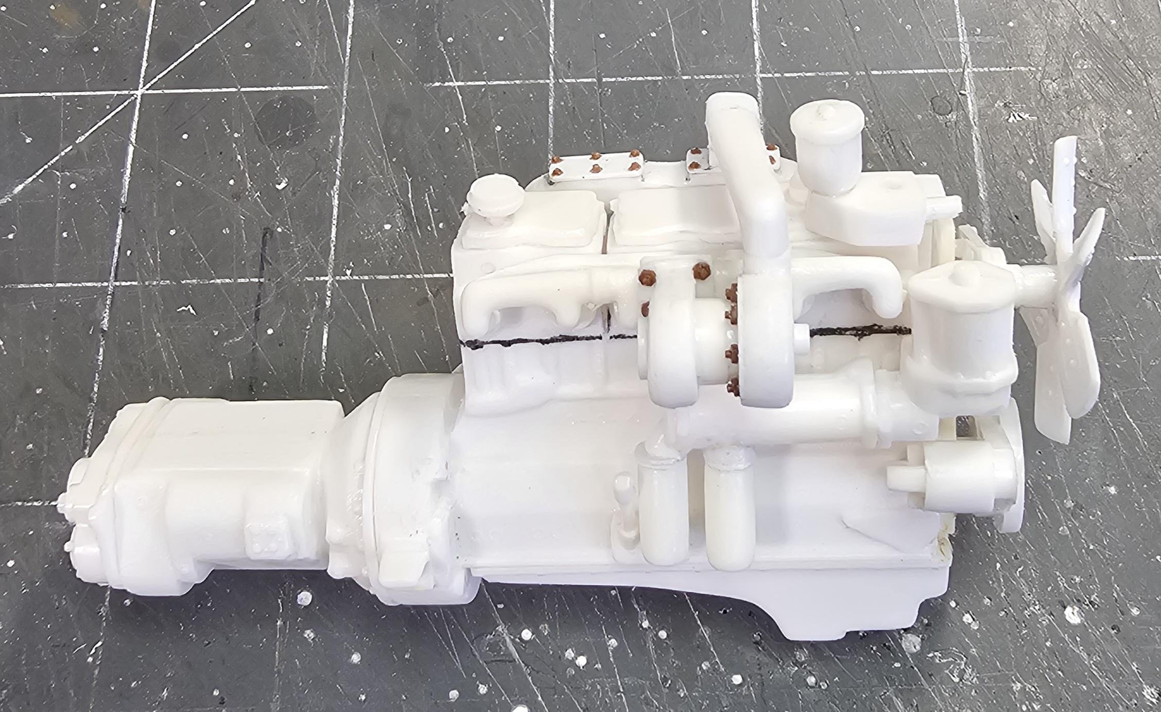
Hey everyone I did some more work on the NTC-290 Cummins. Added details to it. Also just for your information the Revell NTC-475 Cummins does NOT come with a starter moter! You need to steel one from another kit or scratch build one. I'm actually thinking I'm gonna use the NTC-290 instead of the NTC-475 in the Autocar. This view shows the turbos that I moved down to the correct position. Also you can see the Tichy train bolts I added to the turbos. The little brown things. This view shows that I moved the starter to the left side of the engine. This view shows the Tichy bolts I added to the intercooler top plates. You can also see the turbo bolts. This view shows the intake tube on top of the intercooler I scratch built for the turbo. Another view of the turbo intake pipe and turbos. This view shows that you don't get a starter with the Revell NTC-475 Cummins. This view shows the starter I scratch built for another Revell NTC-475 Cummins. Well that's it for now be back soon. Ron G

-
Yupp, it's for the AMT/Italeri 378 kits. Ron G
-
Hey Gary You know that Casey at model truck forum (the guy you got the fenders from) has a 359 long hood for the ROG Peterbilt and the snap Peterbilt, they might fit your cab. And if you are looking for a 379exhd, you can get that from Paul at ST Supply, I know I have one. Ron G
-
AMT "Miller" GMC Astro 95
ShakyCraftsman replied to Goodwrench3's topic in WIP: Model Trucks: Big Rigs and Heavy Equipment
He Jeff That sounds great. Do you know when the next show is in the Detroit or Flint area? Ron G -
All my prayers go to him and he's family. 🙏😇 Ron G
-
AMT "Miller" GMC Astro 95
ShakyCraftsman replied to Goodwrench3's topic in WIP: Model Trucks: Big Rigs and Heavy Equipment
Hey Jeff Any more progress on this build? Ron G -
Hey Gary Send me a PM
-
Hey Scott I have the MicroMark hinge, I used it on my 1/16 Peterbilt, but its to big for 1/25 scale. I also have the Model Garage PE hinge, just didn't want to screw around with PE. Thanks for answering my question. Ron G
-
Hey all Not really an update just pictures of the NTC-475 and the kits NHC-250 that I turned into a NTC-290. This view shows the Revell Cummins NTC-475 on top and the kits NHC-250 that I made into a NTC-290 I still.need to make a connecting pipe from the turbo to the intercooler. This view shows the other side of the engines. Ron G
-
Yes, but he is in the hospital and his site is down and may not come back. You can also get a C-15 from Paul at ST Supply. Ron G
-
Do you have a number?
-
Hey Gary The only twin turbo engines I know of are the Revell Cummins NTC-475 TT and Jeremy's resin Cat C-15 Acert. There not to hard to build, at least the Revell one isn't, hardest part is keeping everything lined up while the glue dries. The Cat is alot trickier, there are NO instructions to go by. I have some pictures I got from Jeremy for the C-15 to show how to go about assembling it. If you want I can PM them to you. Ron G
-
Yupp!
-
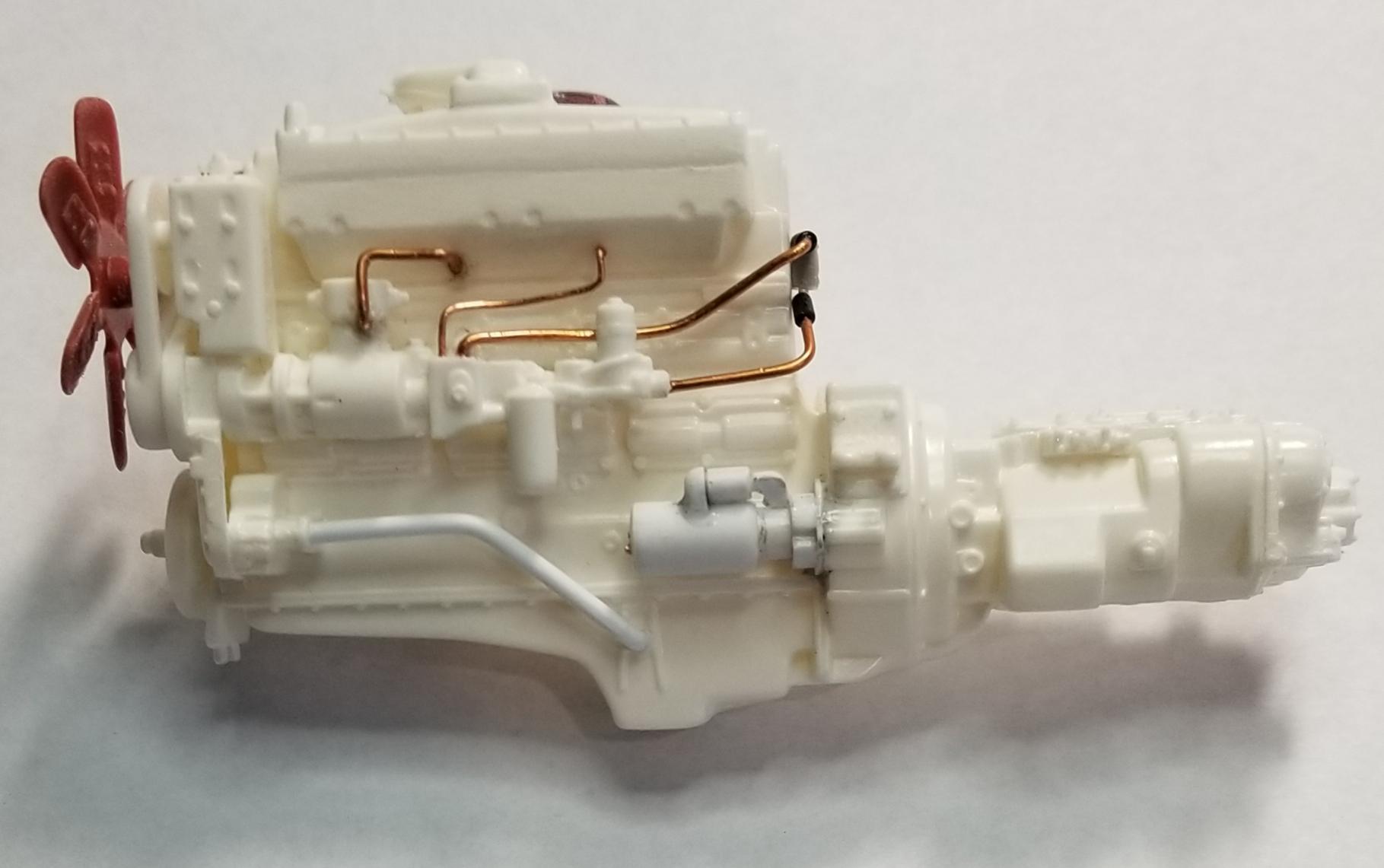
Hey all More work done on the Autocar. This is a picture of Matt's truck. This view shows the 475 assembled and the pipe I added to the oil pan and the front of the engine. This view shows the other side of the 475 with the twin turbos. This view shows the engine with some pre detail paint added. Well that's it for now be back with more soon. Ron G
-
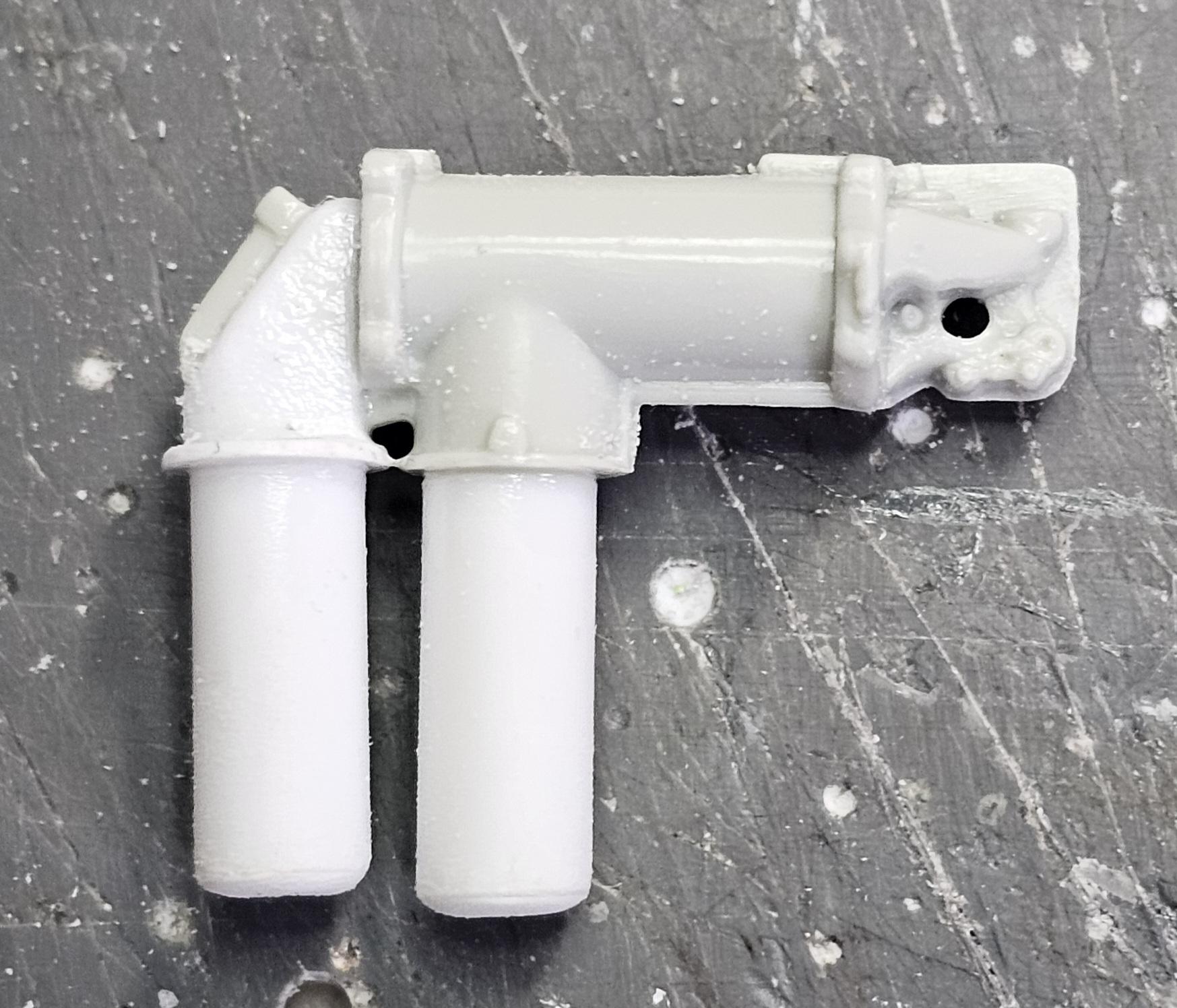
Hey all So, just as Matt's going to do, I'm replacing the small cam Cummins NHC-250 with a Revell Cummins NTC-475 TT. Although Matt is using a big cam 400 (both 855's). This view shows the kit 250 on the left and the 475 on the right. Something other side. Amt on top Revell on the bottom. This view shows the air compressor/fuel pump on the left and the oil cooler on the right. This view shows that I filled in the back of these pieces to make them look more realistic. This view shows the oil cooler after I made it into a twin filter version. Back side of the oil cooler. This view shows the oil cooler mounted to the engine. It also shows the pipe I added to the front of the engine. This view shows the air compressor/fuel pump mounted on the engine. Ron G
-
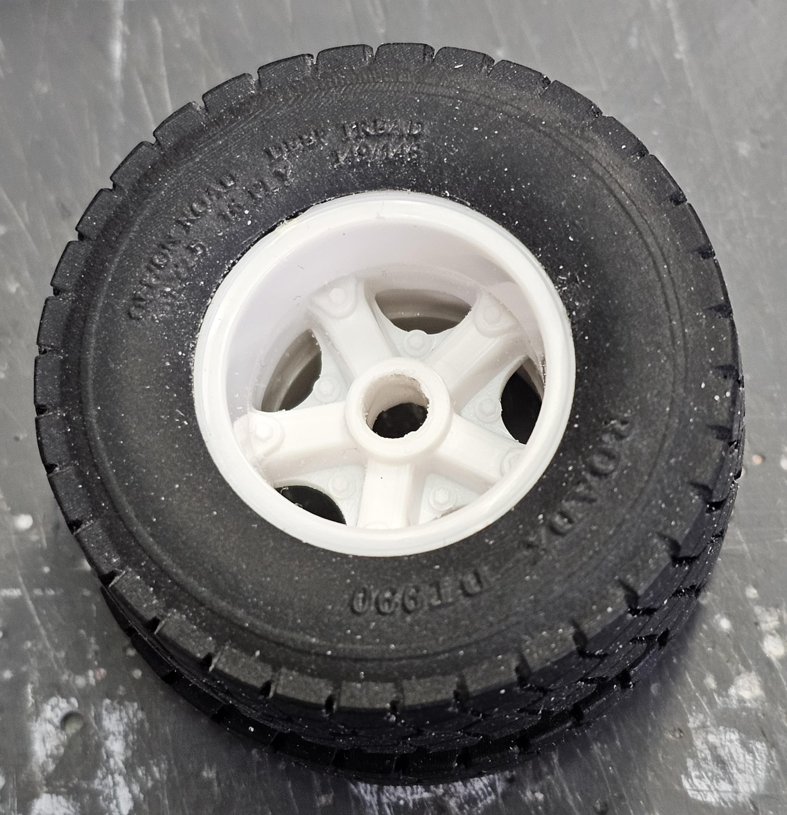
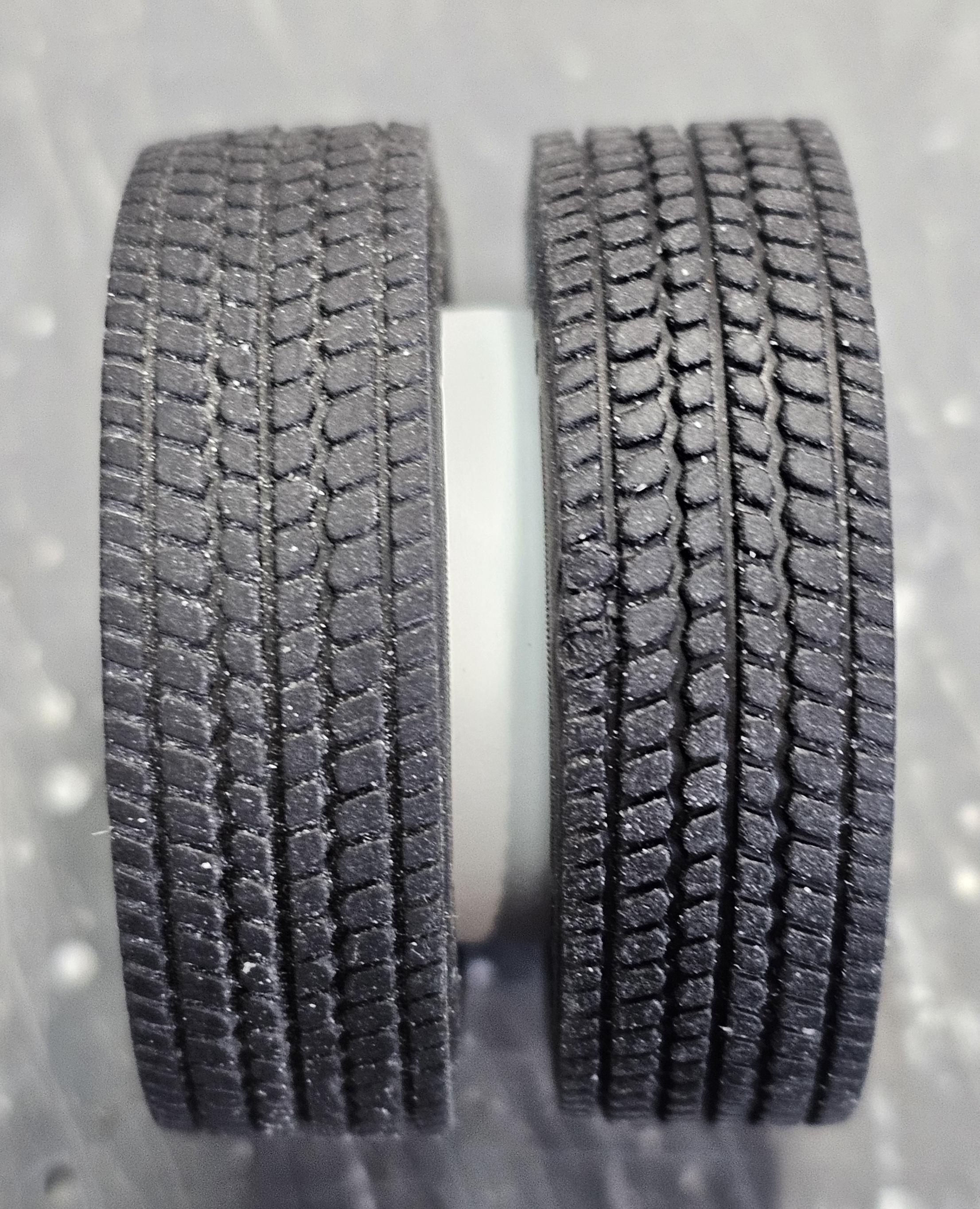
Hello Everybody Okay, before everyone goes crazy. I didn't want to start this build right now. I received the AMT Autocar DC-9964B dump truck kit from Amazon. I was originally going to build Stallone's truck from "Over the Top". While doing research for it I came across "Diesel Creeks" videos on his (Matt) 1980 DK-64 Constructor and after watching the videos I decided to make a kinda version of Matt's truck. I actually just went to the bench to trial fit some tires to the Autocar's rims to see if they fit. They are the 22.5 RoadX TD990 from Paul at ST Supply. I wanted to see if they would fit the rims and voila! They fit. As you can see they fit good and tight. View looking at the tread. View looking at the back. Like I said they fit good. But I think they are to tall and aggressive for the truck I want to build. So, as I was trying the tire fit, I started to look for tires that would work. And digging through my stash I found some that I think will work just fine. This turned into more investigation into my version of Matt's truck.
-
Hey Tom I just found this build and I went through all 10 pages. You Sir are a fantastic Imagineer! Your skills are up there with the best on here. I do have a question how ever, how did you make the piano hinges on your doors? Did you buy them? Scratch build them? If you made them could you list what you used please. Thanks Ron G
-
Mo'luminum?
ShakyCraftsman replied to ShakyCraftsman's topic in WIP: Model Trucks: Big Rigs and Heavy Equipment
That really sucks! He made some assume parts for trucks. Sadly another aftermarket provider bits the dust. 😥😢 Ron G -
Mo'luminum?
ShakyCraftsman replied to ShakyCraftsman's topic in WIP: Model Trucks: Big Rigs and Heavy Equipment
Wow! That's terrible. Hope he recovers soon. All my best. Ron G -
Hey all Anyone know what happened to Mo'luminum? The site says he's not taking any orders now? And I really need some of his pintle hooks.🫤 Ron G
-
Hey Bill I'm going to be doing almost the same thing, as soon as I finish a few builds. I'm using the AMT Autocar dc-9964b dump truck kit. I'm putting a Revell Cummins NTC-475 in it, kinda like what Matt is doing. It will be a Heavyhaul tractor. If you have any questions just ask, this forum is great for that. Ron G
-
Hey Gary Just because a person or company can 3D print a part, doesn't mean they know anything about engineering it. Alot of people design there parts in scale, instead of one to one and then printing it to scale. This generates all lot of mistakes, or errorors in translation. I was an Automotive/Aircraft CAD designer for 30+ years, so I know what I'm saying, plus my son owned a 3D printing business that I helped in designing stuff for him. Ron G
-
Thanks everyone. Ron G
-
I think they look perfect on your KW! Ron G