-
Posts
797 -
Joined
-
Last visited
Content Type
Profiles
Forums
Events
Gallery
Everything posted by ShakyCraftsman
-
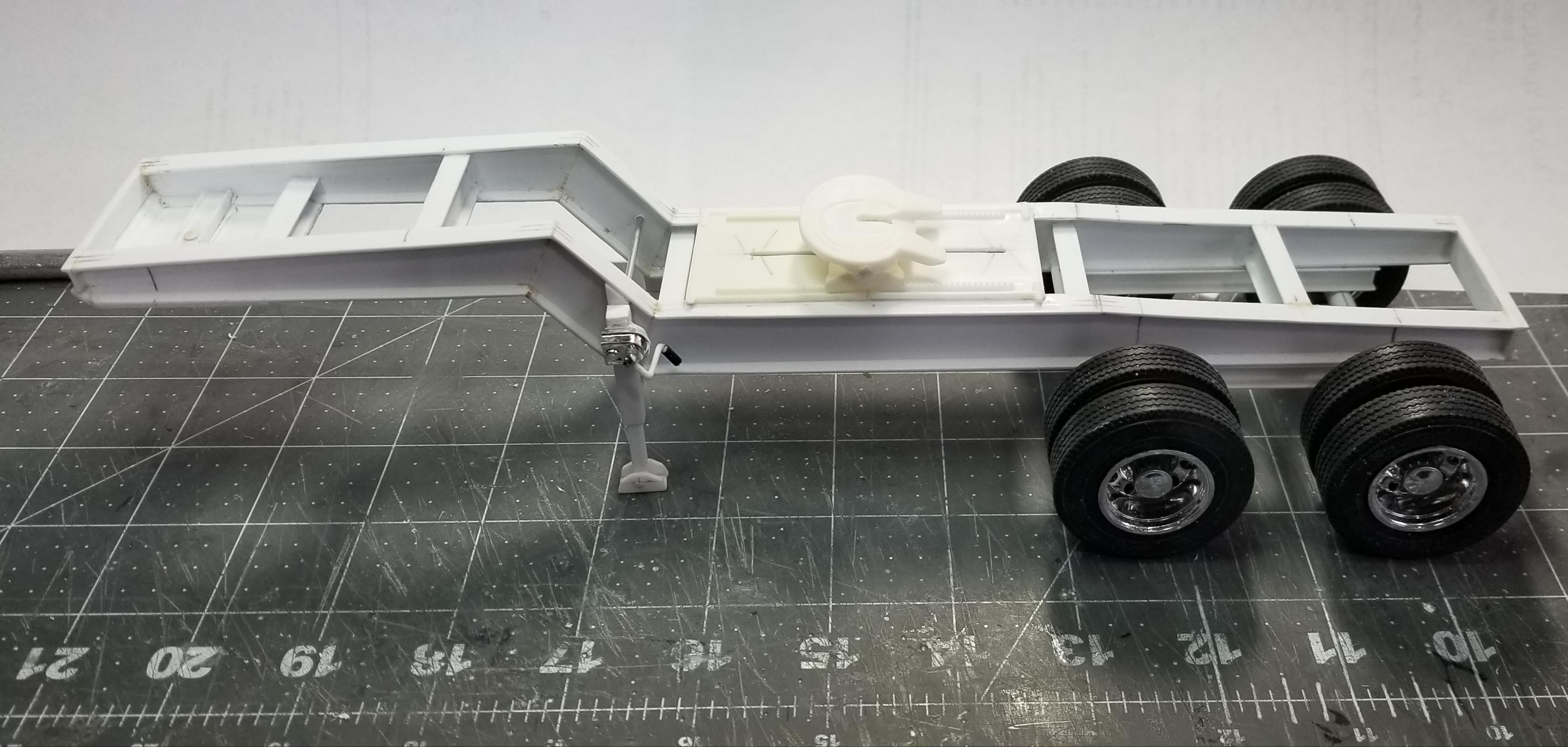
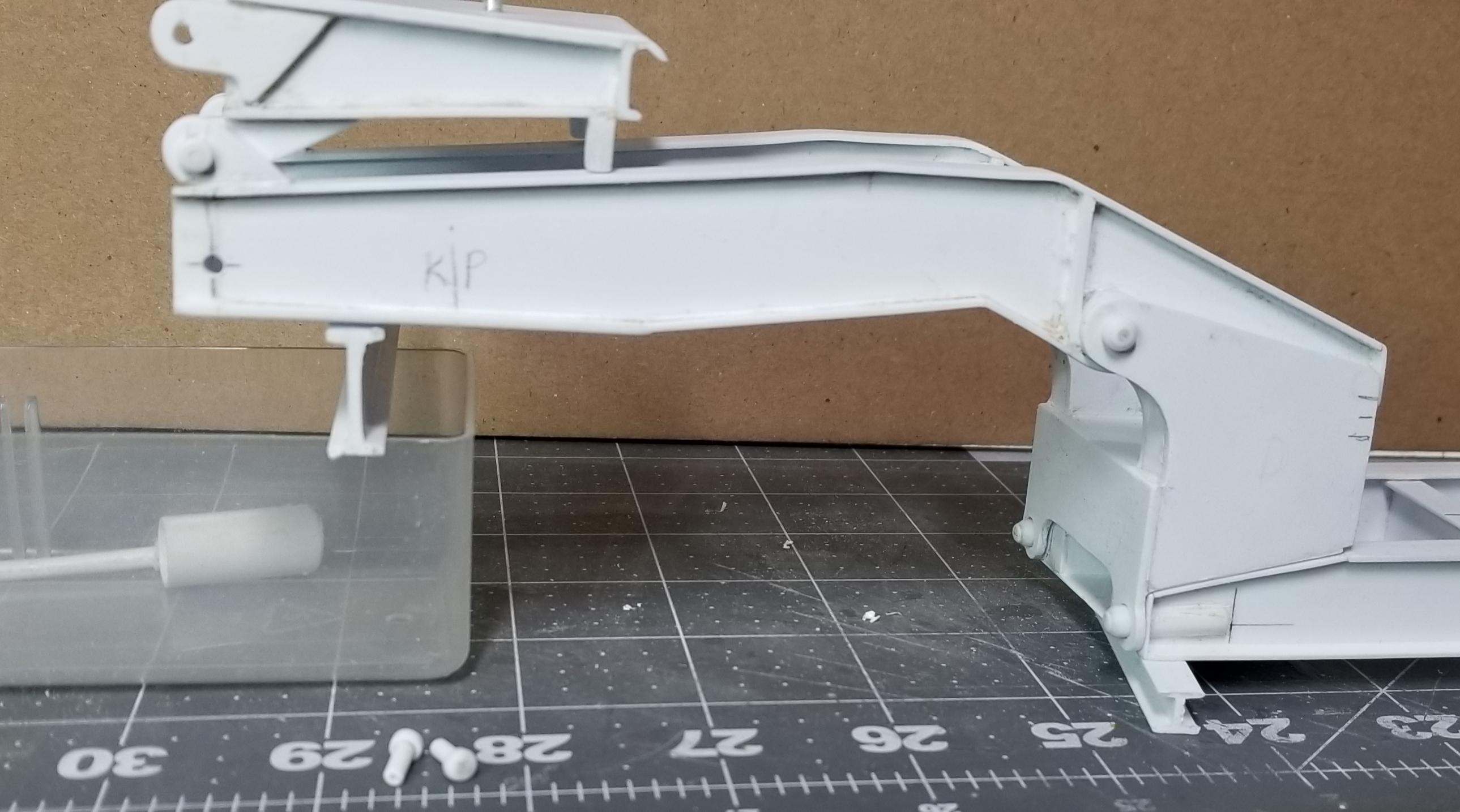
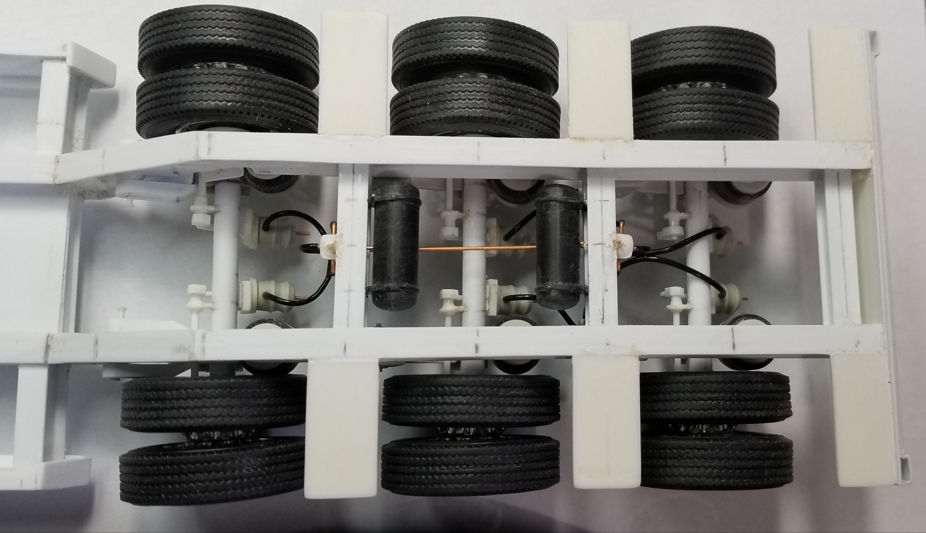
Hey Ron This is my Heavy Haul trailer set-up. About 80% scratch built. It's a XL SPECIALIZED XL120 RGN Lowboy, Jeep and Stinger. That's my attempt at trying to scratch build a Cat 374F excavator sitting on the trailer. This view shows the whole set-up. It's about 5 feet long! This is the load equalizing stinger. This view is the jeep. This view shows the flippable gooseneck. This view shows the trailer deck. This view shows the trailer rear suspension. (I know the brakes are caged, I've since fixed this). I'm not trying to appropriate your post. Just showing what you can do by scratch building one.😁😉👍 One of these days I'm going to have to finish it. Ron G
-
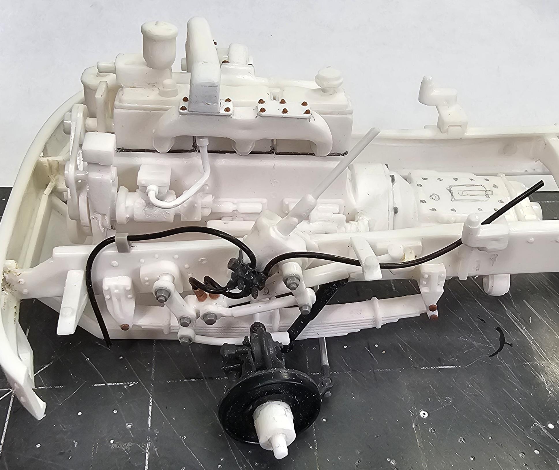
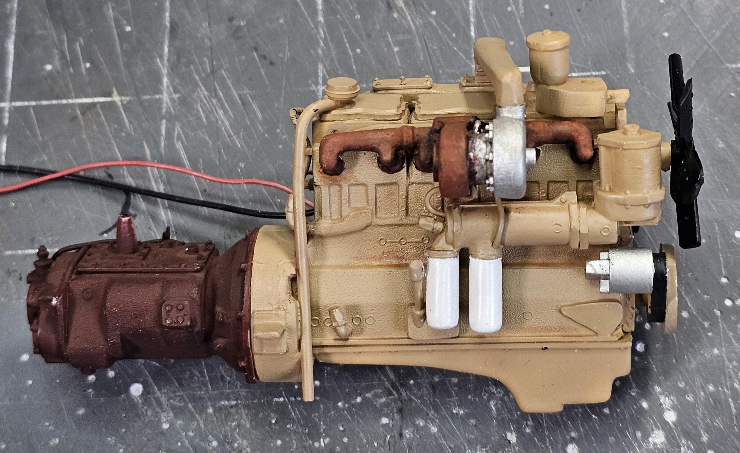
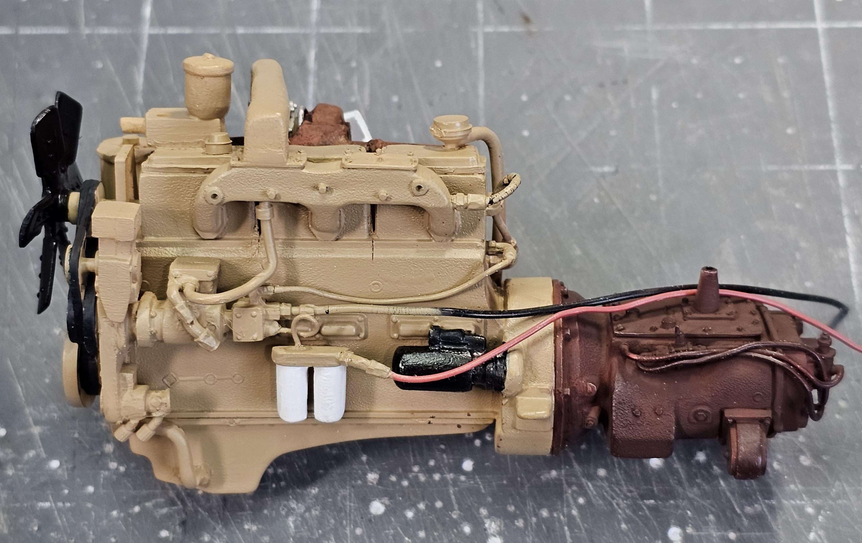
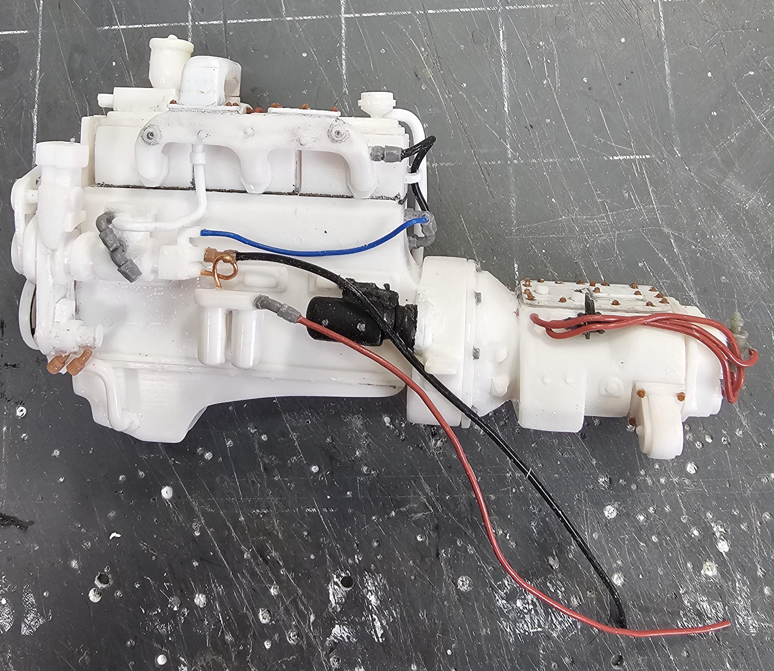
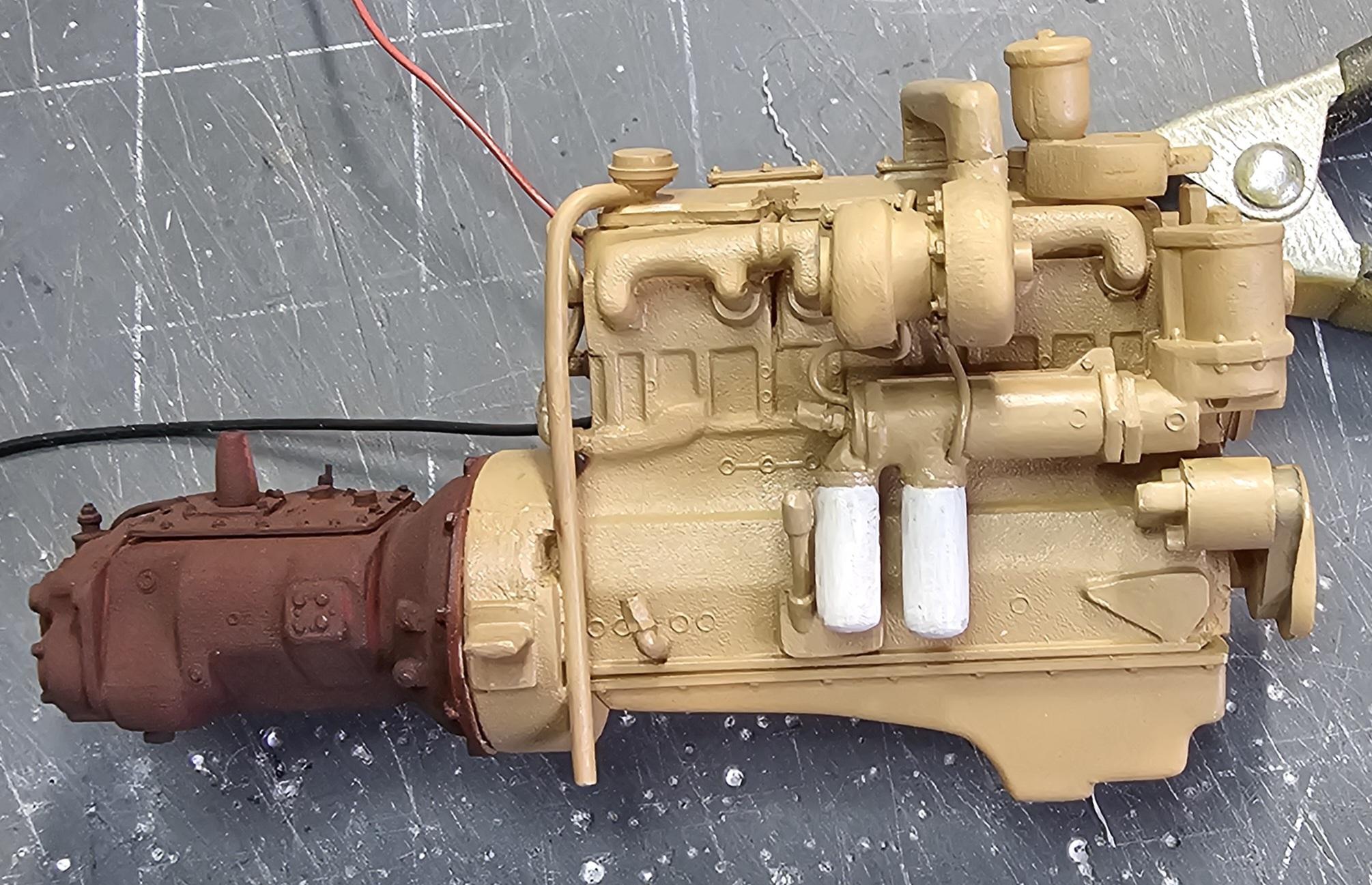
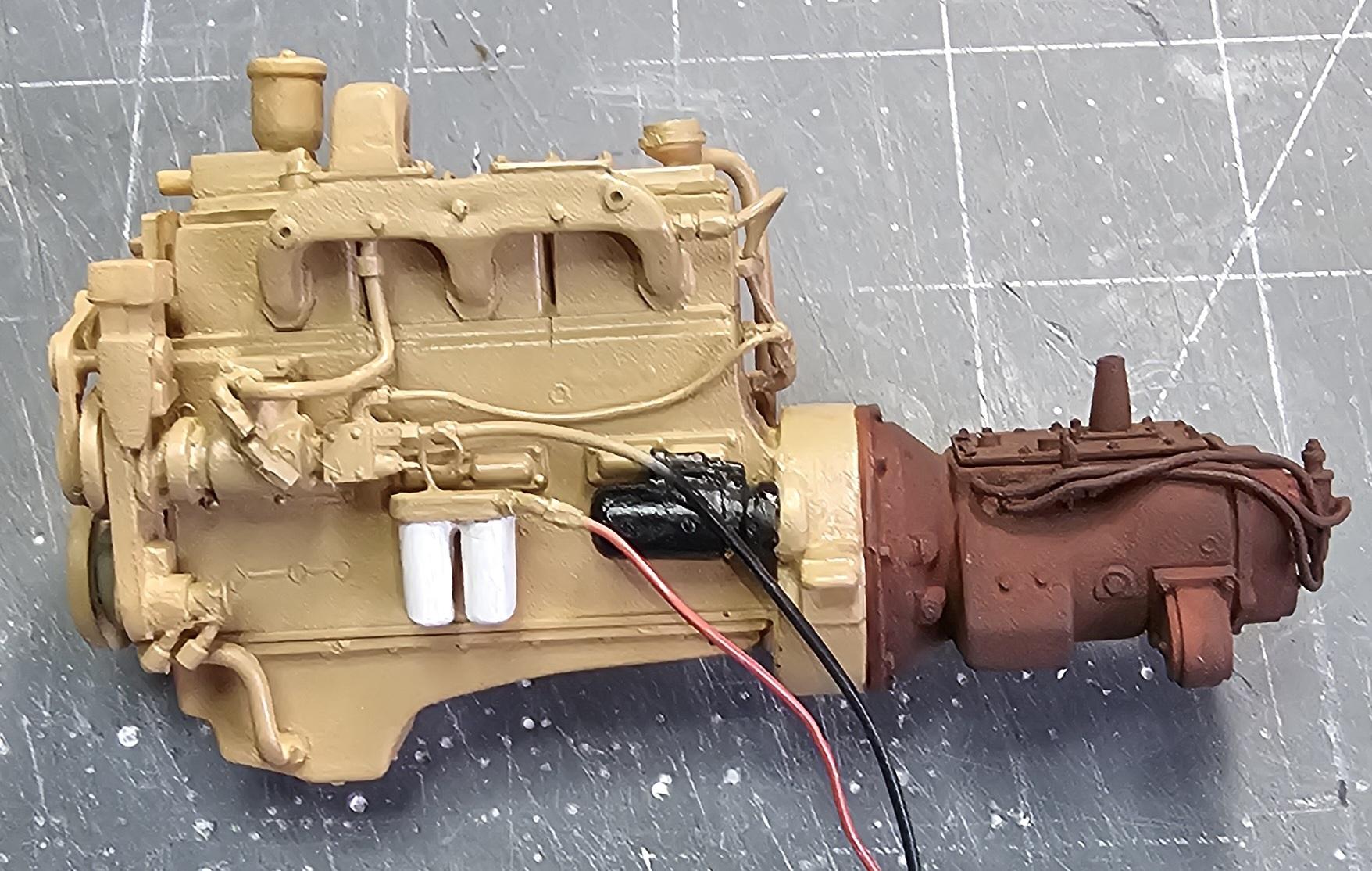
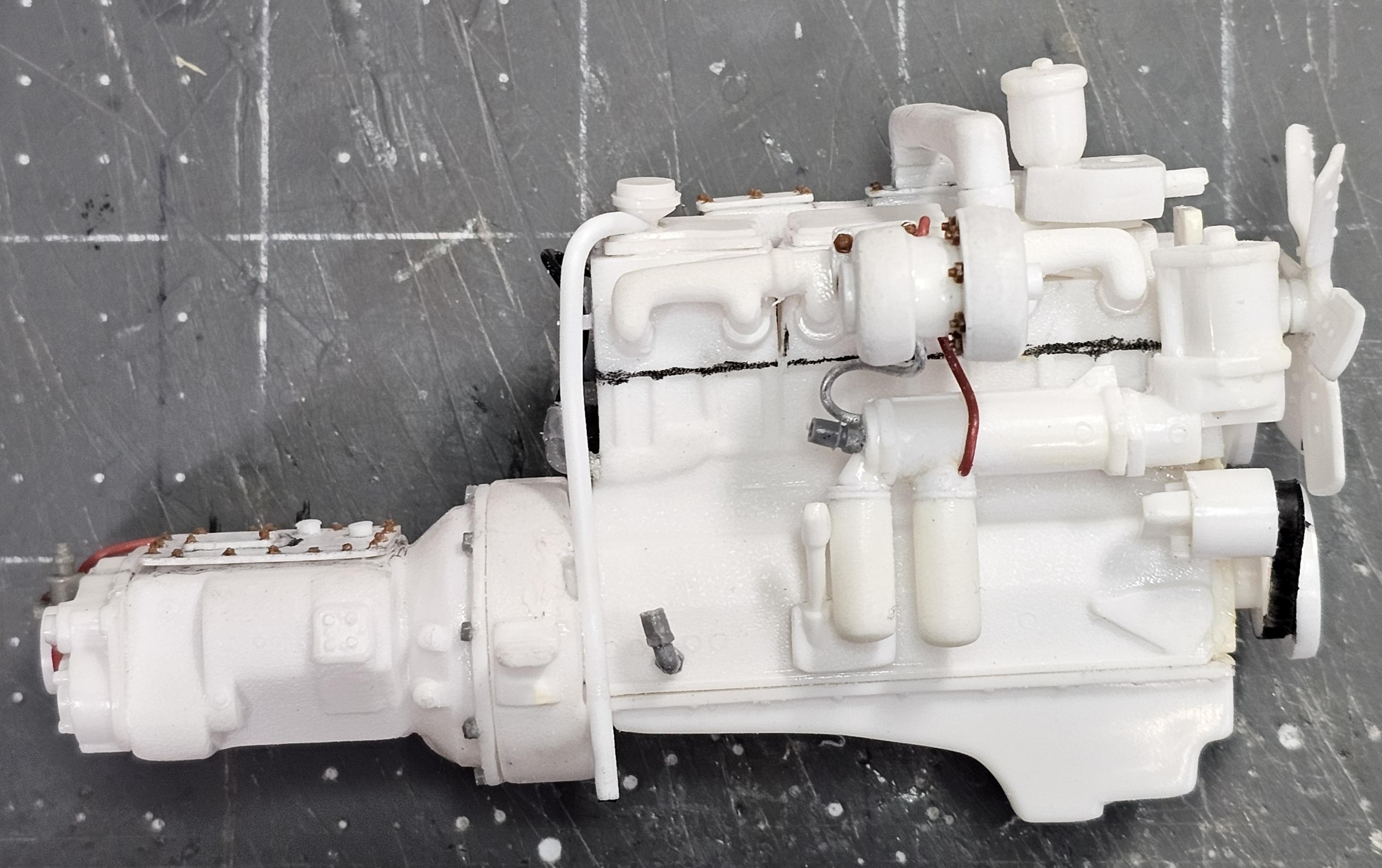
Hey all I didn't get much done today on the Autocar. I have an eye condition that acts up every now and then. It makes every thing blurry, so I can't model.😫😢 I did manage to get the NTC-290 Cummins painting finished before my eyes crapped out. All that it needs now is some weathering and plumbing and it will be all set. Front view of the engine showing the fan & belts. Passenger side view shows the oil filters, alternator & turbos. This view shows the fuel filters & a little of the fan belts. Top down view of the engine showing the rusting on the exhaust turbo. View from the front. And this is it in place in the frame. I think it looks the part. Oh, I also made a drive shaft out of some left overs from the KFS front drive axle kit I used on my Alberta oilfield bed truck build. These are real nice drive shafts. Pretty good detail to them. Well that's it for today be back soon. Ron G
-
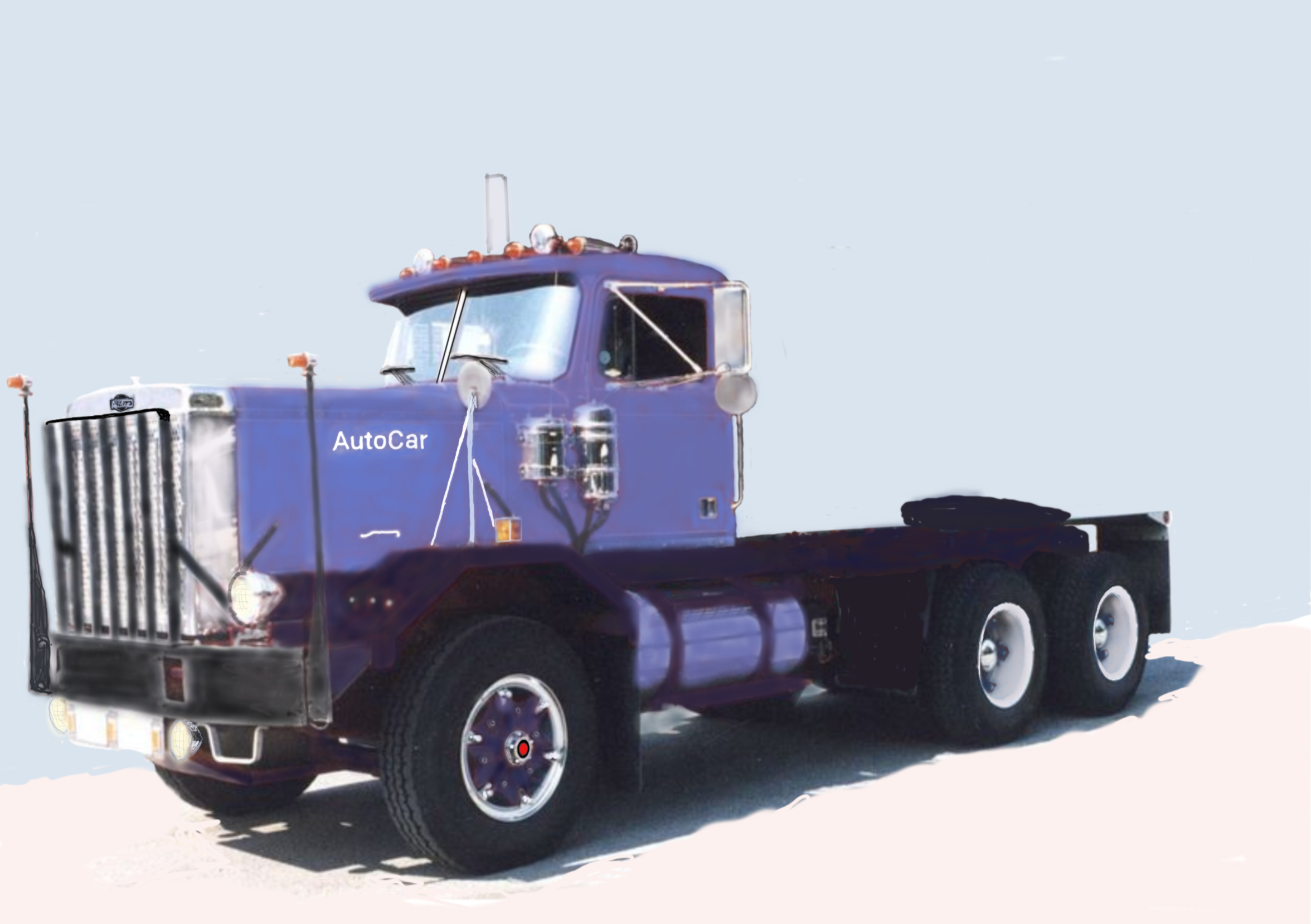
Hey all Didn't work on the Autocar model today, but I did work on the paint scheme for it. This picture shows a very traditional Autocar paint scheme. At least in the East it is. This picture is the one I am leaning towards the most. This is a possibility orange and brown. This is also a possibility L. blue & D. blue. This is a variation on the one I like,but with the colors reversed. Well I have alot of thinking to do cause I'm at the frame painting stage. I'll be back soon with my decision. Ron G
-
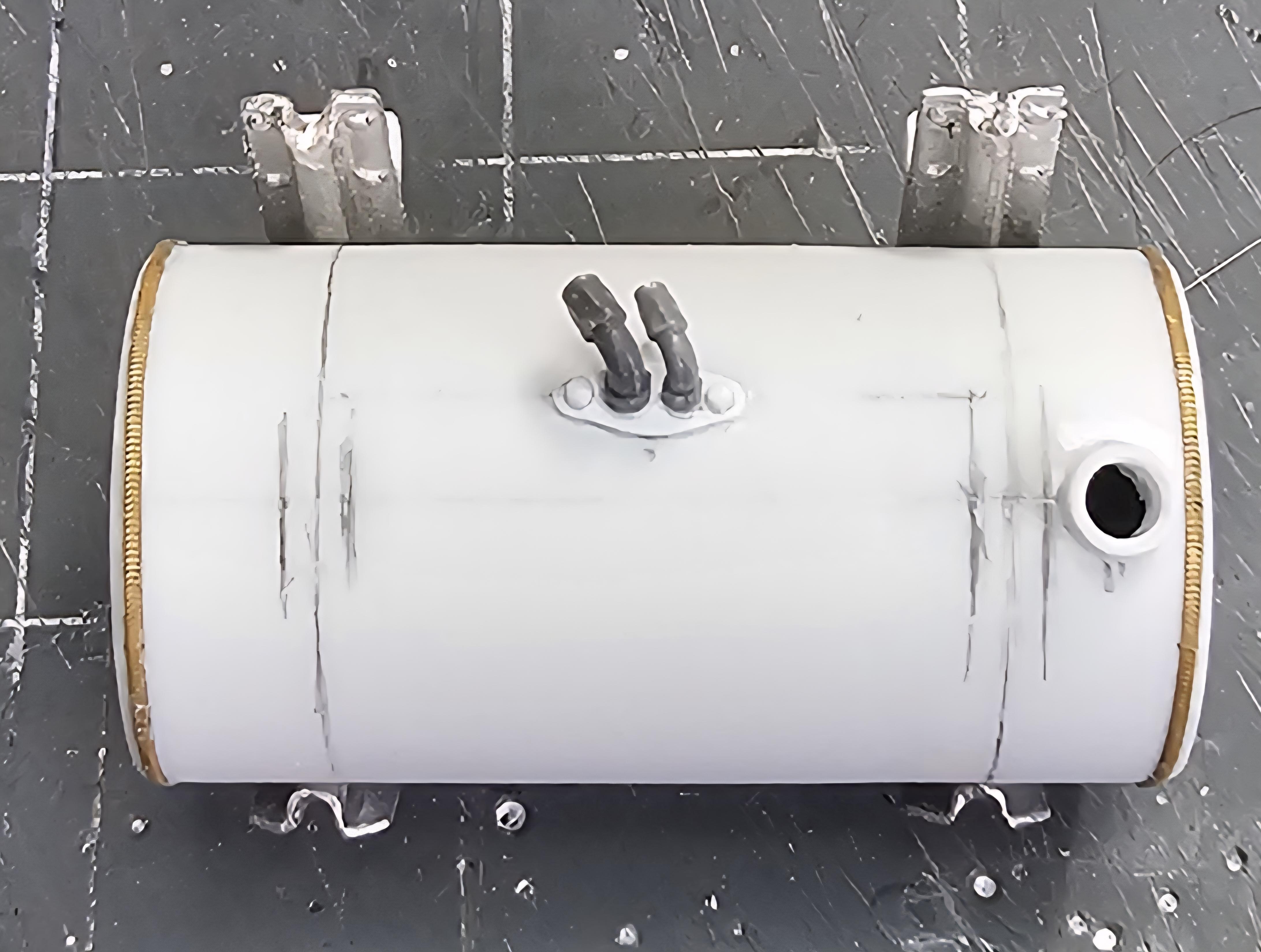
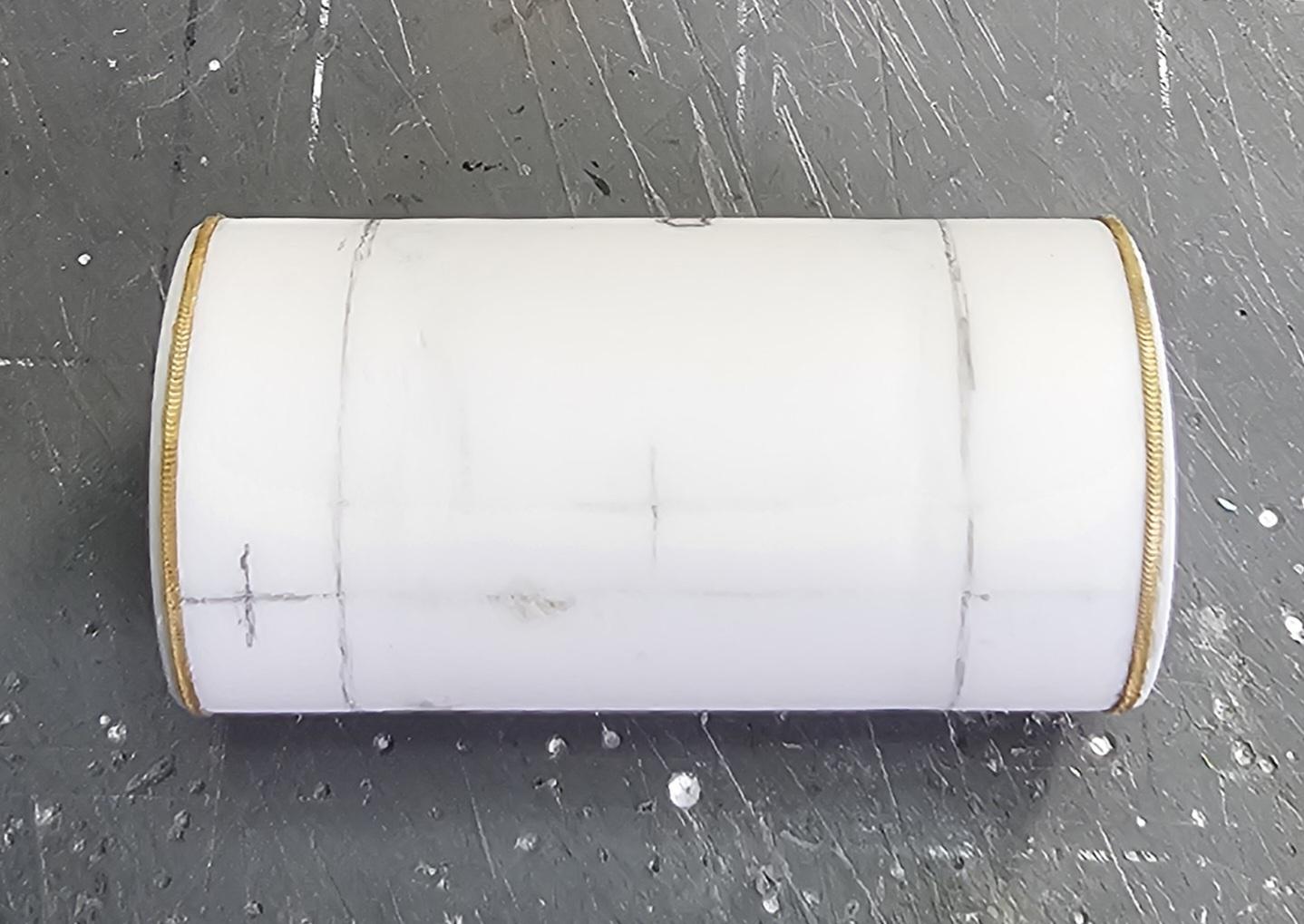
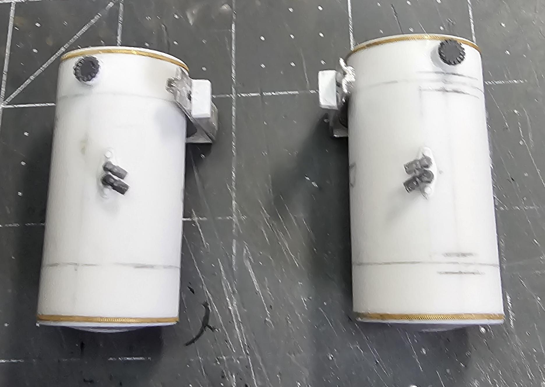
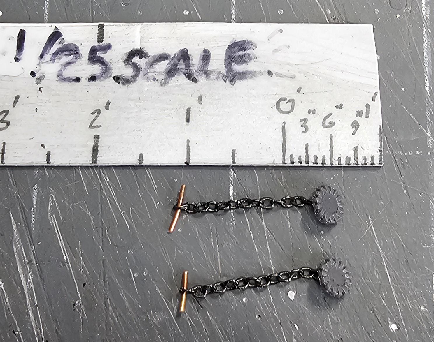
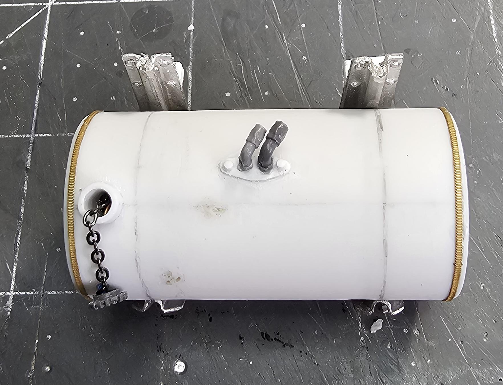
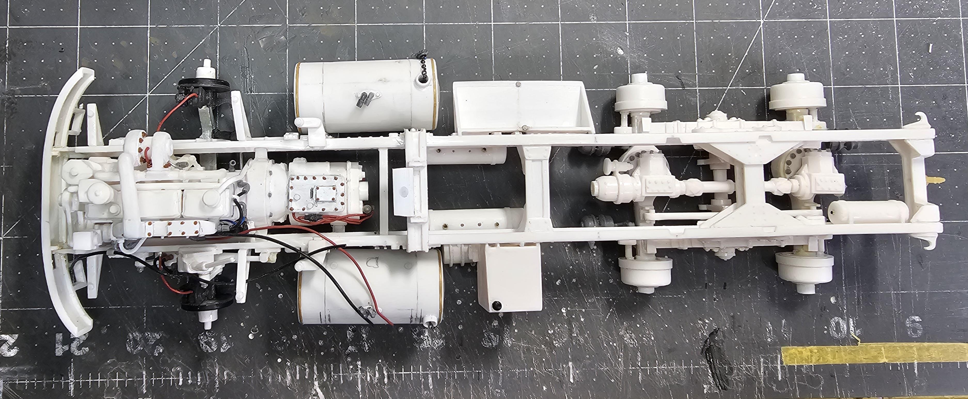
Hello Everybody Well I got some more work done on this build. I worked on the fuel tanks, power steering reservoir and lubrafiner, hood and the engine. This view shows the drivers side fuel tank with the brass weld beads and fuel fittings that I added. This view shows the drain fitting on the bottom of the fuel tank. This view shows the tank before adding fittings and fuel filler neck. This view shows both fuel tanks done and ready for paint or dull aluminuming. This view shows the tanks with there fuel caps. This view shows the modifications I did to the fuel caps. (I know it's kinda anal...lol)😁 This View shows the cap hanging on it's chain. This view shows the cap in place. This view shows the tanks sitting on the frame. I had to bend these fittings up so that they will clear the front fender. I sprayed some Tamiya semi-gloss black on the inside of the hood. This view shows the front brake lines and fittings added to the frame. This view shows the oil drain plug and transmission drain plug I added. This view shows the black fuel feed line and the red return line added to the fuel pump & fuel filters on the engine. This view shows the shift tower I added to the transmission top cover. I got a little color added to the NTC-290 Cummins. This view shows the other side of the engine. Still more detail painting to be done plus weathering. Well that's it for now be back soon with more. Ron G
-
Hey everyone Small update today. I worked on the NTC-290 Cummins for the Autocar by adding some details and plumbing. It doesn't look like much work, but those fittings are very fiddly and time consuming. This view shows the oil lines added to the turbos. It shows the two fittings that will eventually connect to the luberfiner. Also I added a valve cover vent tube to the engine. This view shows the line added from the fuel filters to the fuel pump (loop). I also added a fitting to the fuel pump that will attach to the line from the tank. I added a fuel feed line from the pump to the head. Also a line from the block to the intake manifold all with fittings. It's hard to see but I added two flat head screws to the starter moter with a rivet making tool and sharp #11 blade (the silver dots). You can just barely see the tiny Tichy bolts I added to the PTO on the trans. This view shows the transmission shift lines and valves. Also the lines running to the head. A closer look at the starter screws. This view shows the air filter can I'm going to use for this build. It's from a Revell ROG Peterbilt kit, modified slightly. Well that's it for now be back soon with more updates. Ron G
-
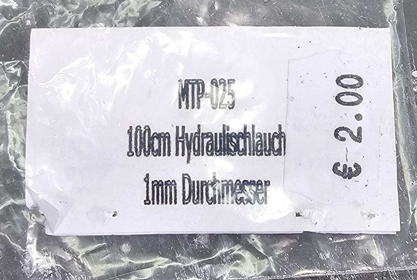
They are from CTM and are actually not hollow, they are a rubber cord to be specific. They come in their hydraulic fittings and rubber lines kit #24007. They are 1.0mm (0.984"), 1.5mm (1.476") & 1.9mm (1.870") in diameter. They also sell the 1.0mm & 1.5mm in individual packs. Thanks Pal for your comments. Ron G
-
Hello Everybody I got a little more work done on this build today. This view shows the power steering reservoir and lubrafiner temperaly attached to the cab. This view shows the battery box that I modified. I cut the two (don't know why there were two in the kit) boxes ends off and then joined them together to make a bigger box to fit all four of the batteries in it. This view shows the battery box lid and box with the kit batteries sitting in it. I took the lid and added tiny Tamiya magnets and a couple of tiny pieces of metal to it to keep it closed. This view shows the fuel tank I'm using and the brass weld beads that I'm adding to it. This view shows the batteries. I cut them in half. AMT molded them together. Dumb. This view shows the four batteries I ended up with. I'm cutting all the molded on detail off like the bottom right so I can add on better details. This view shows the step I added to the frame. This view shows the fuel tank and mounting brackets. This view shows the detail I added to the battery, just three more to do. This view shows the transmission top cover I scratch built and the Tichy bolts that I added to it. Well that's it for today be back soon. Ron G
-
If you are talking about the fittings they are these. They are from CTM (Czech Truck Models) I got them from Paul at ST Supply. If you were talking about the hinges they are from Micromark. I don't have a number, they didn't have one. They are the ones redneckrigger used on his link belt crane build. He listed the number. Check his post for number. Ron G
-
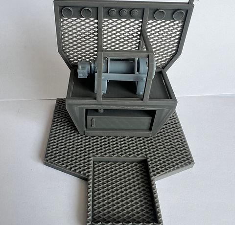
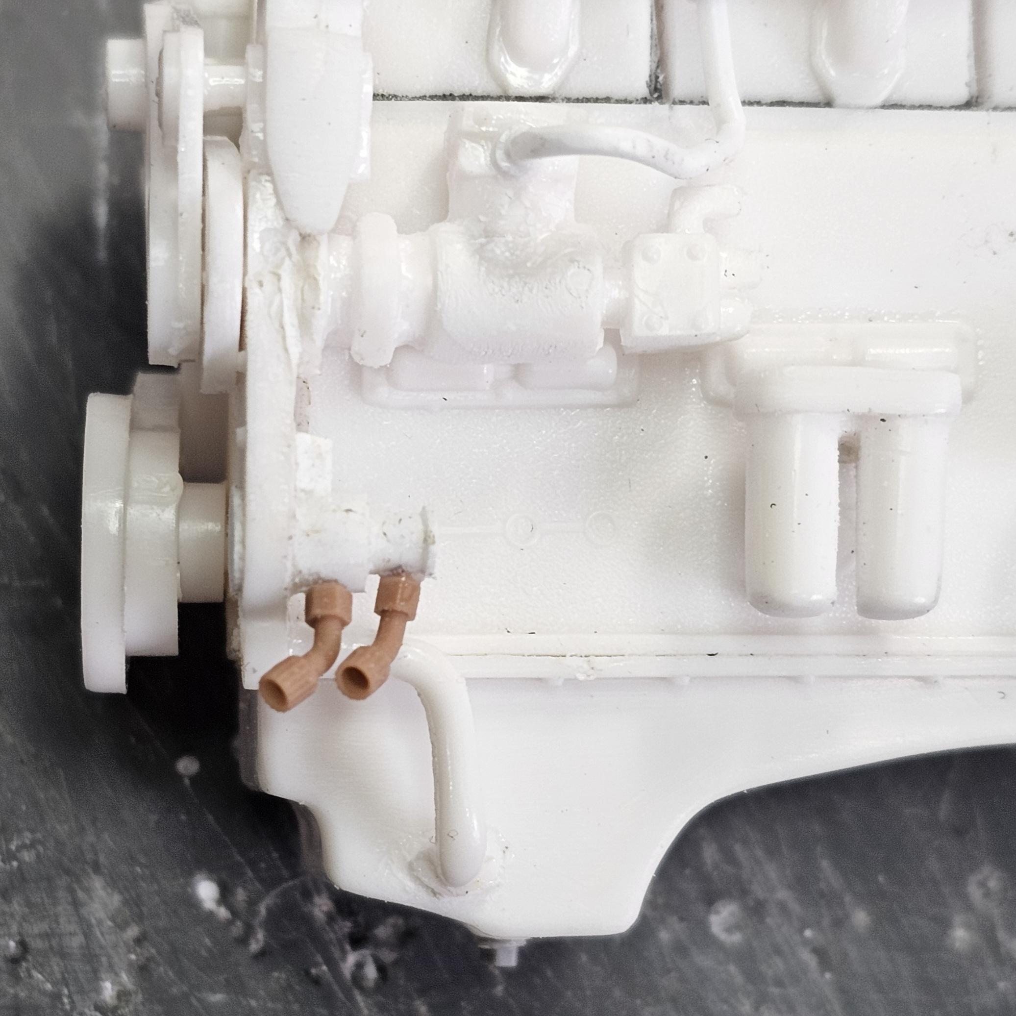
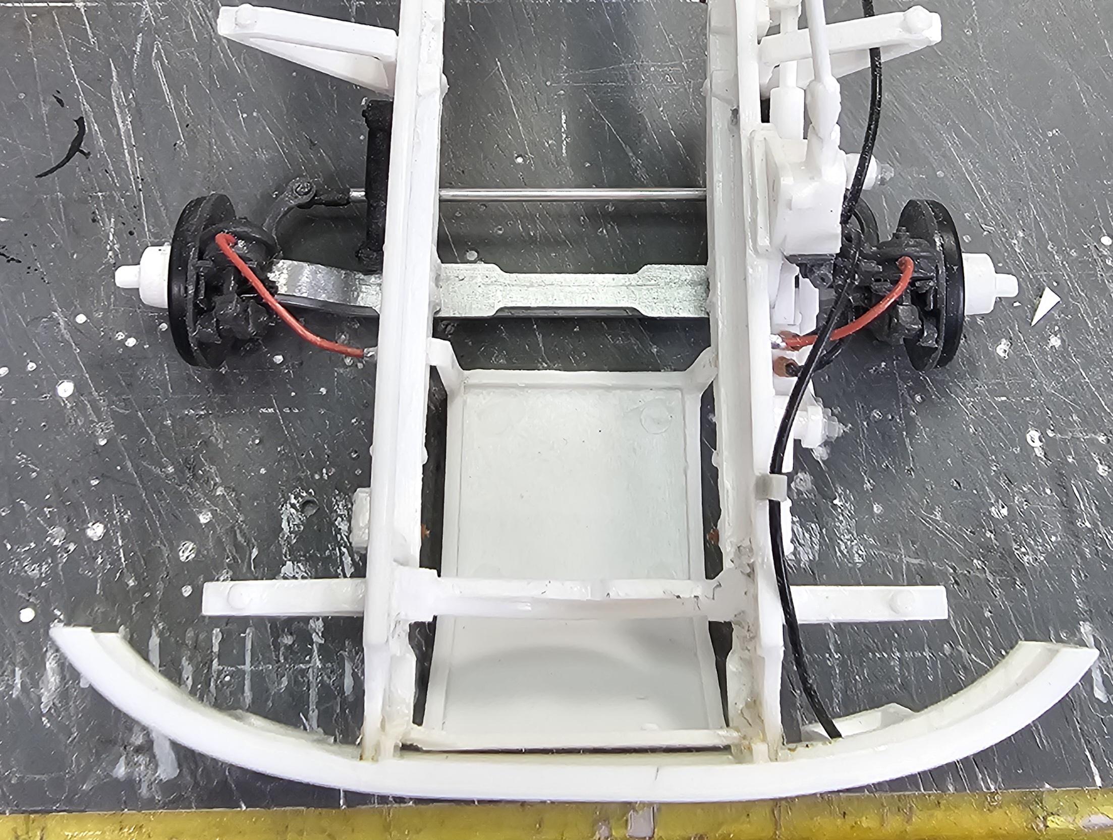
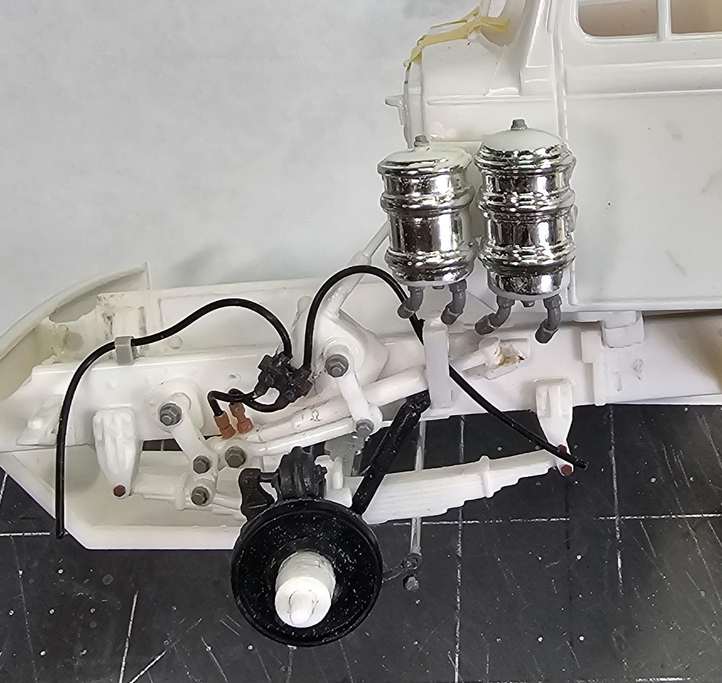
Hey all Got some more work done on this build. Started the front steering system plumbing. This view shows the floor that I added to the kit interior bucket. This view shows what the floor looks like on the truck. This view shows the parts I'm using to plumb the front steering mechanism. They are from CTM. This view shows the steering box control valves that I added. This view shows the different front wheel centers I'm thinking about using. I'm going with the oil center cap, on the right. This view shows the rear wheel center caps I'm going to use. This is the winch headache rack I'm going to be using. This view shows the headache rack. It's from 3D Concepts. This view shows the two tan hydraulic fittings I added to the front hydraulic steering assist cylinder. Also the bolt heads I added to the front steering mechanism. This view shows the hydraulic fittings I added to the hydraulic pump. This view shows the plumbing on the front steering system. I can't add more till the truck is further along. This view shows the radiator to cab bracing rods. This view shows the hood in place and open on the truck. Well that's it for now I'll be back soon with more updates. Ron G
-
Hey Tom I know exactly what you mean. No matter how good I do something it just doesn't meet my vision, to much of a perfectionist I guess.😆 It can be a curse, but also a good thing, because it makes us better modelers. Keep up the outstanding work you are doing I definitely want to see this done. Ron G
-
Yeah, I tought it was a little big, but it looks okay on your build, doesn't stand out. If you look at my Autocar build I used the little hinges (forgot what #) to make a long piano hinge for my hoods center hinge. I then used two on each side for the side hinges, worked out perfectly. All this was inspired by you and your build. Thanks Ron G






.png.5bd268fd4f46966d4175298f01b11df8.png)














.png.aef1274f97edf672cd78fb21727f6b1a.png)
