BK9300
-
Posts
1,986 -
Joined
-
Last visited
Content Type
Profiles
Forums
Events
Gallery
Everything posted by BK9300
-

Freightliner FLC
BK9300 replied to Jürgen M.'s topic in WIP: Model Trucks: Big Rigs and Heavy Equipment
Nice work, Jurgen - good ideas! -
Western Star 4900 FA plow truck
BK9300 replied to BK9300's topic in WIP: Model Trucks: Big Rigs and Heavy Equipment
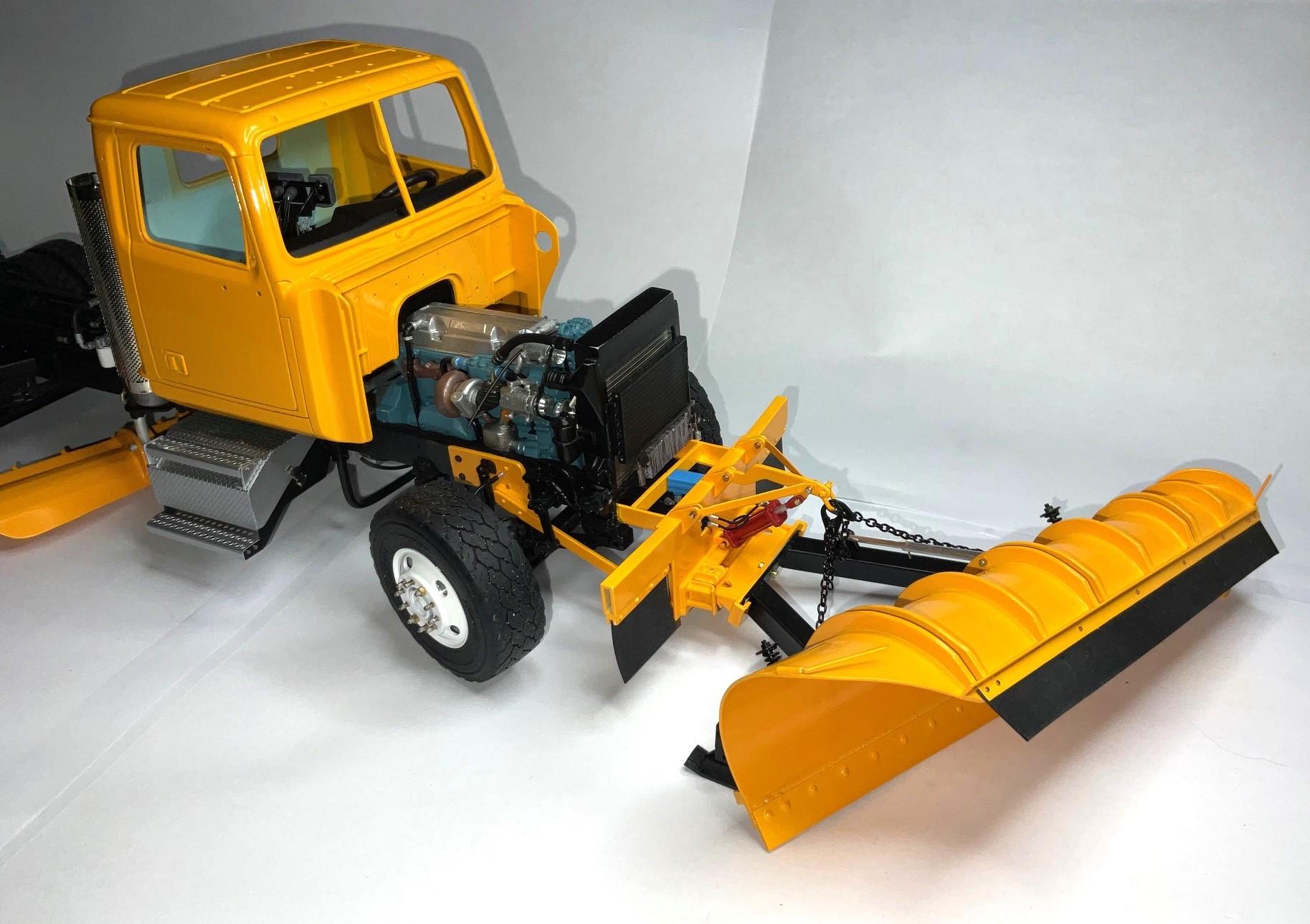
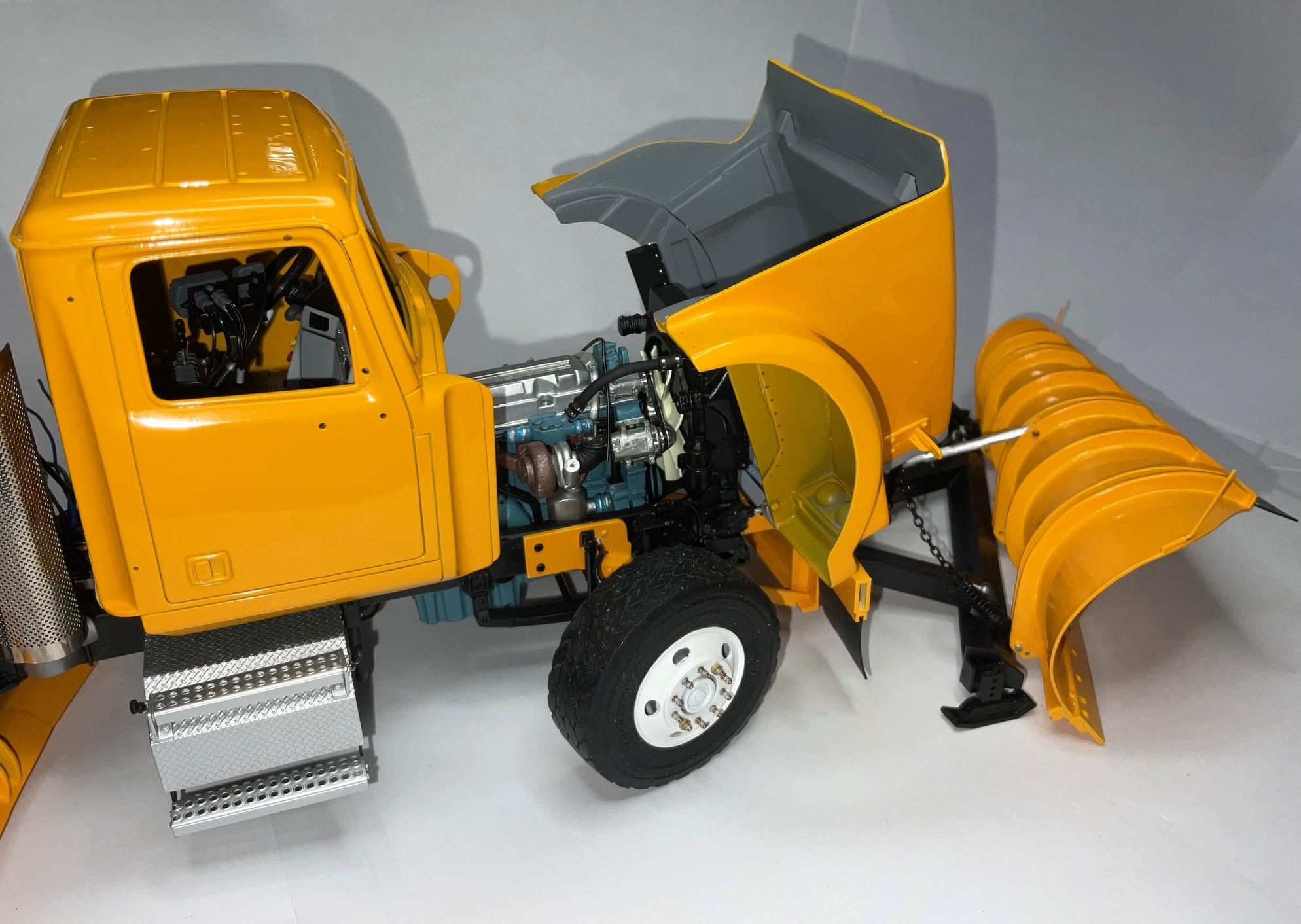
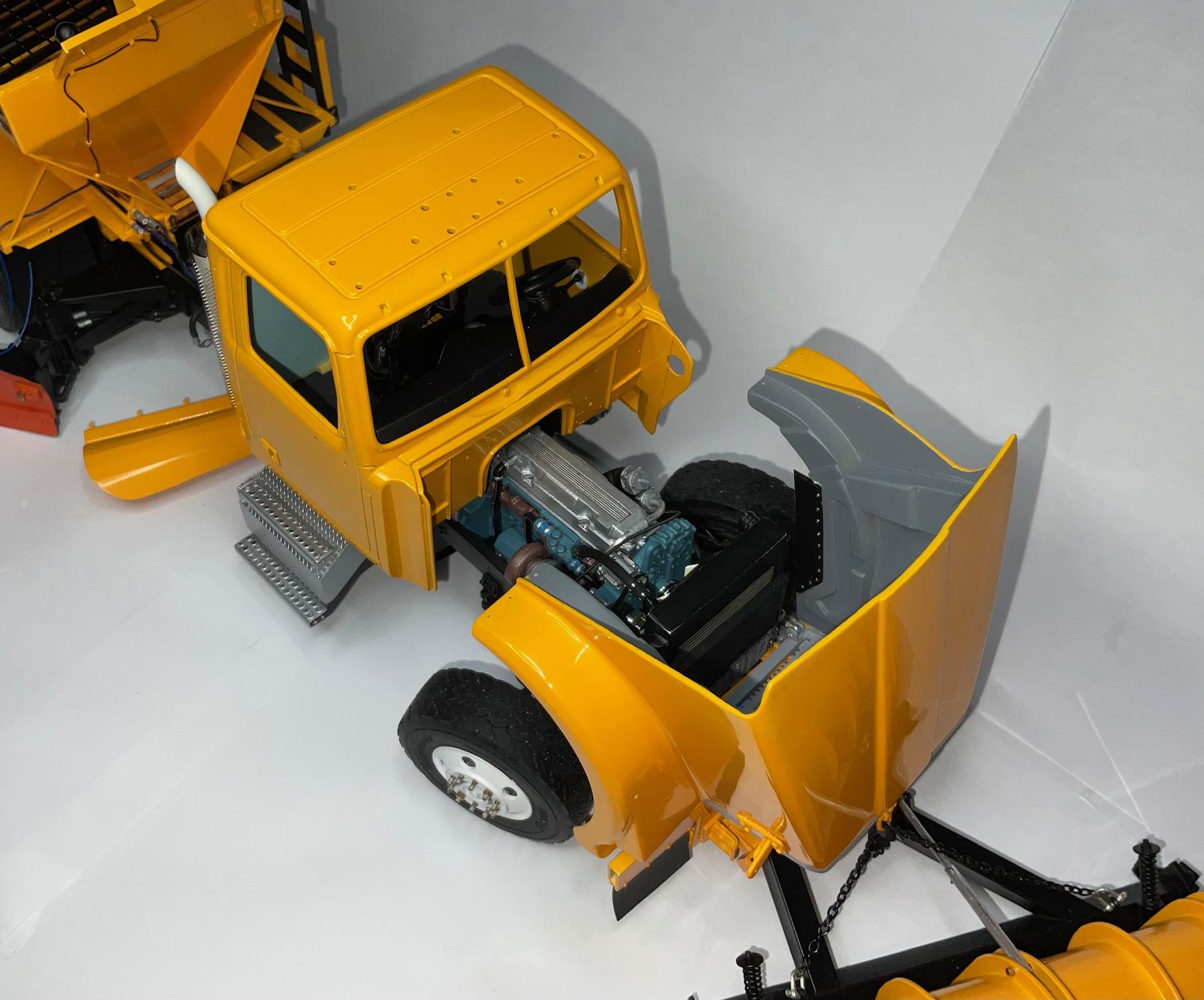
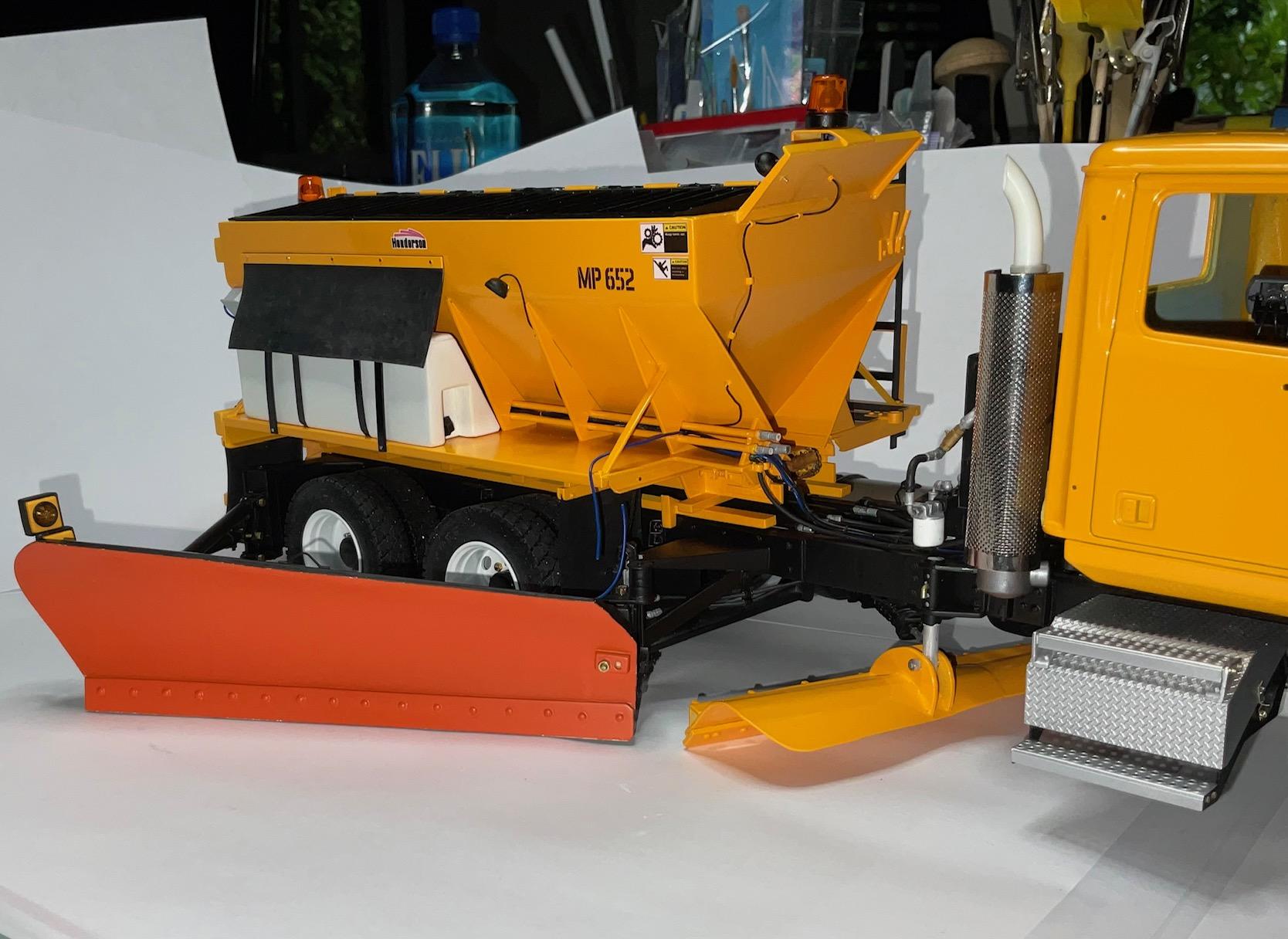
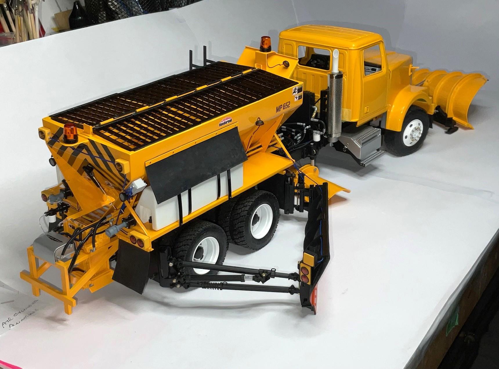
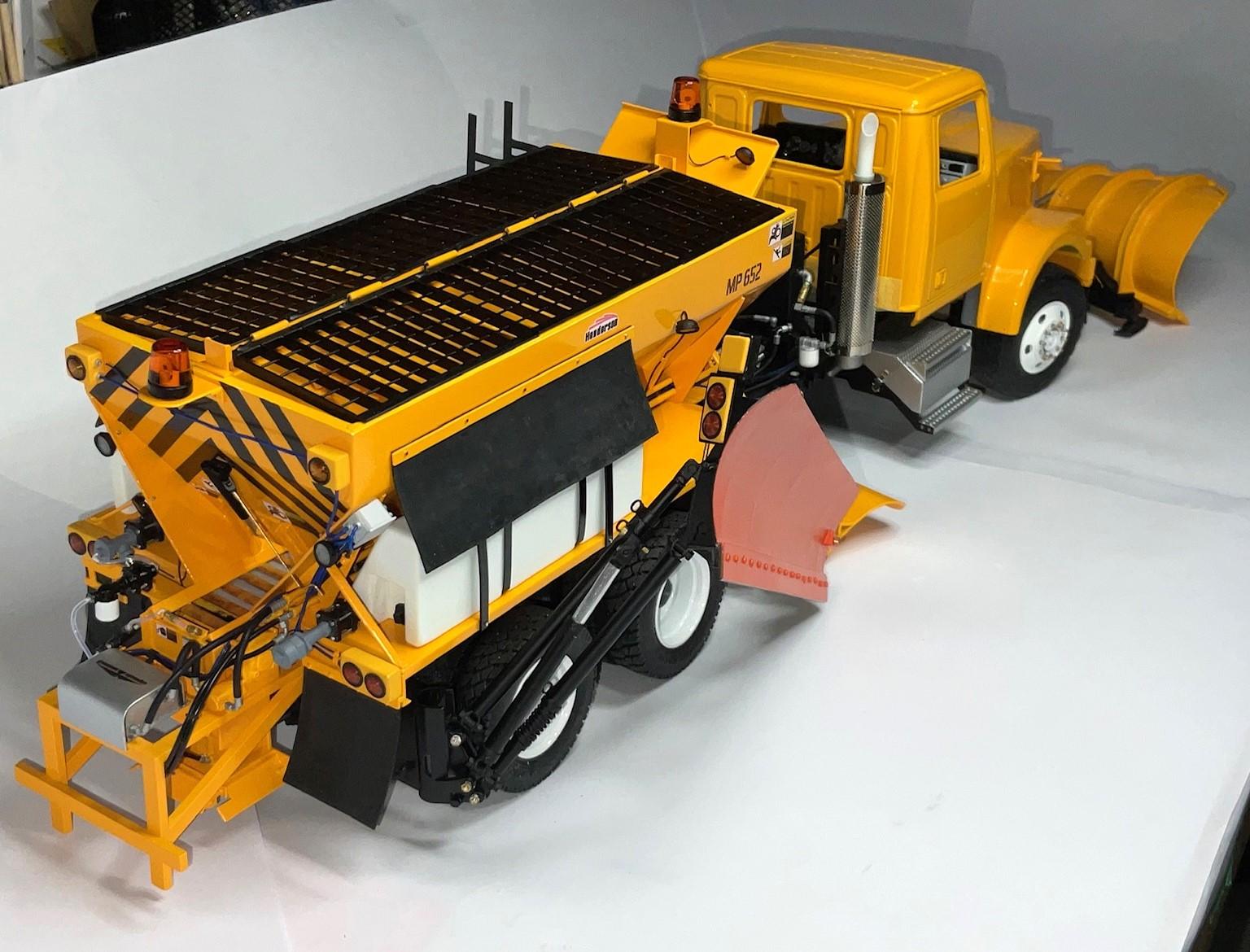
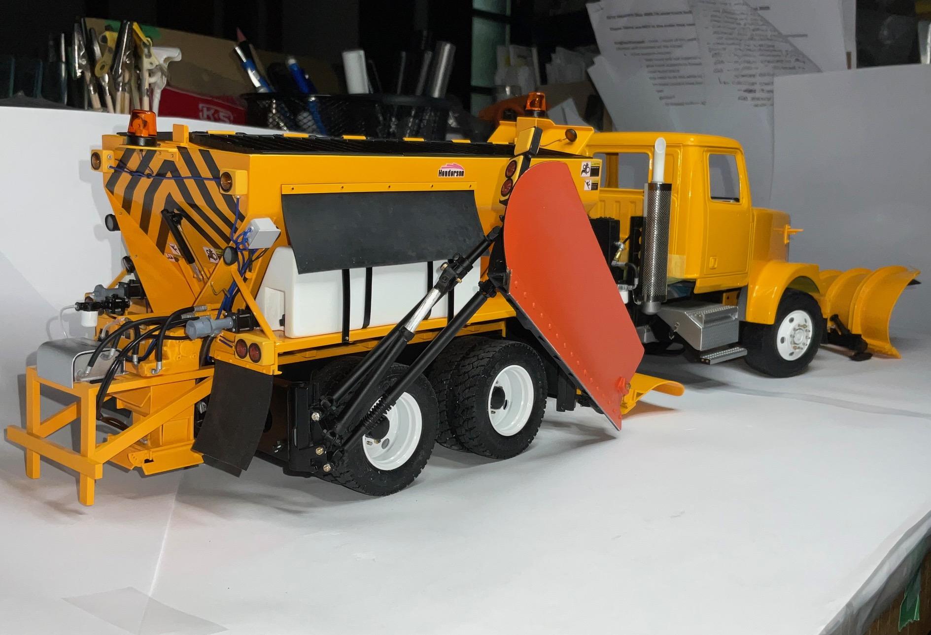
Been a rainy day here and didn't get much of anything accomplished - just wasn't sure which of several areas needing attention I should attack first. I started out, innocently enough, to mount the wing plow, because many months ago, I had a binding problem that wouldn't let the plow fold up as far as I wanted. Well, that led to me re-assembling most everything I could. This is just a bunch of pics of that effort and, after all that, I do have some clearer idea about what to do next! Pretty pleased with how this truck looks, all put together - even with more work to do yet. (because it was darker outside today, needed to use flash on iPad - I think that is what’s making the blue cast in some of the pics) - This is as close to the truck as I could get the wing plow - it's quite close to the pics I have, but maybe not all the way - Have to start in with cab detailing next week - just about there!
-
Kenworth W-925 (mild custom)
BK9300 replied to Gary Chastain's topic in WIP: Model Trucks: Big Rigs and Heavy Equipment
Fine looking truck, Gary - looks very classy! -
Kenworth W-925 (mild custom)
BK9300 replied to Gary Chastain's topic in WIP: Model Trucks: Big Rigs and Heavy Equipment
Hope that feeling doesn't last - good news is, it looks like you've taken care of those printer lines! -
Freightliner FLC
BK9300 replied to Jürgen M.'s topic in WIP: Model Trucks: Big Rigs and Heavy Equipment
Apart from printing most of your own parts, you also hand fabricate other, custom pieces to add in, too! Great progress, Jurgen, and I hear you may have another resin printed hood and cab on their way to you. Going to look wonderful. -
Like others have already said, your attention to detail, landscaping and weathering are stunning! I’d bet there isn’t a square millimeter of your diorama that hasn’t had some attention from your weathering technique(s). Hard to fathom the work that must go into something like this!
-
Western Star 4900 FA plow truck
BK9300 replied to BK9300's topic in WIP: Model Trucks: Big Rigs and Heavy Equipment
Thanks very much, guys - I appreciate it! -
65 IMPALA PRO-TOURING: what to do of an unexpected gift?
BK9300 replied to Claude Thibodeau's topic in Model Cars
Another stunner, Claude - beautiful overall, and especially like your work on the frame. -
Beautiful work on your exhaust, Daniel - those are very tiny bits to work with!
-
Awesome paint, stance, engine, and, well, awesome everything - beautiful! (carbs through the hood)
-
Western Star 4900 FA plow truck
BK9300 replied to BK9300's topic in WIP: Model Trucks: Big Rigs and Heavy Equipment
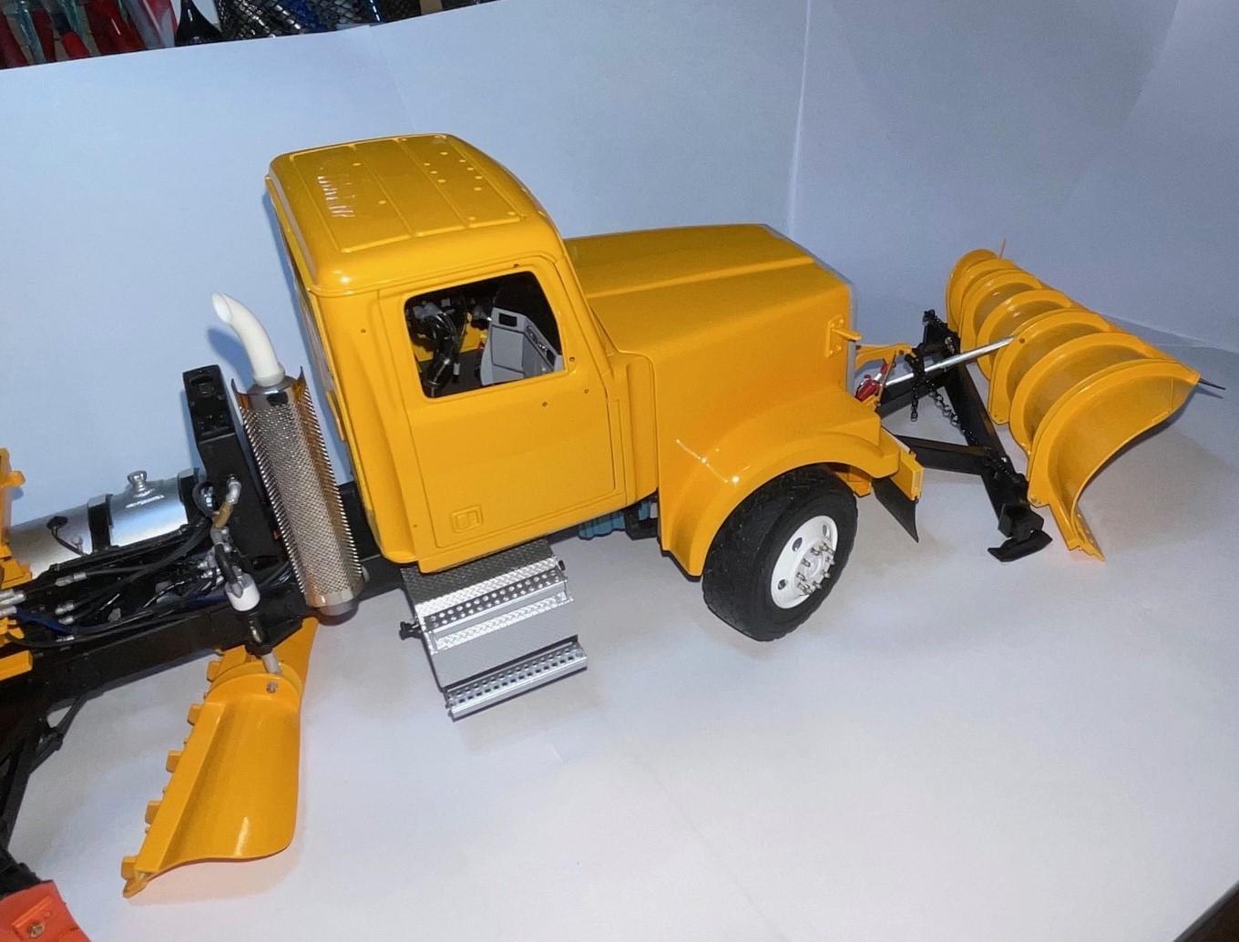
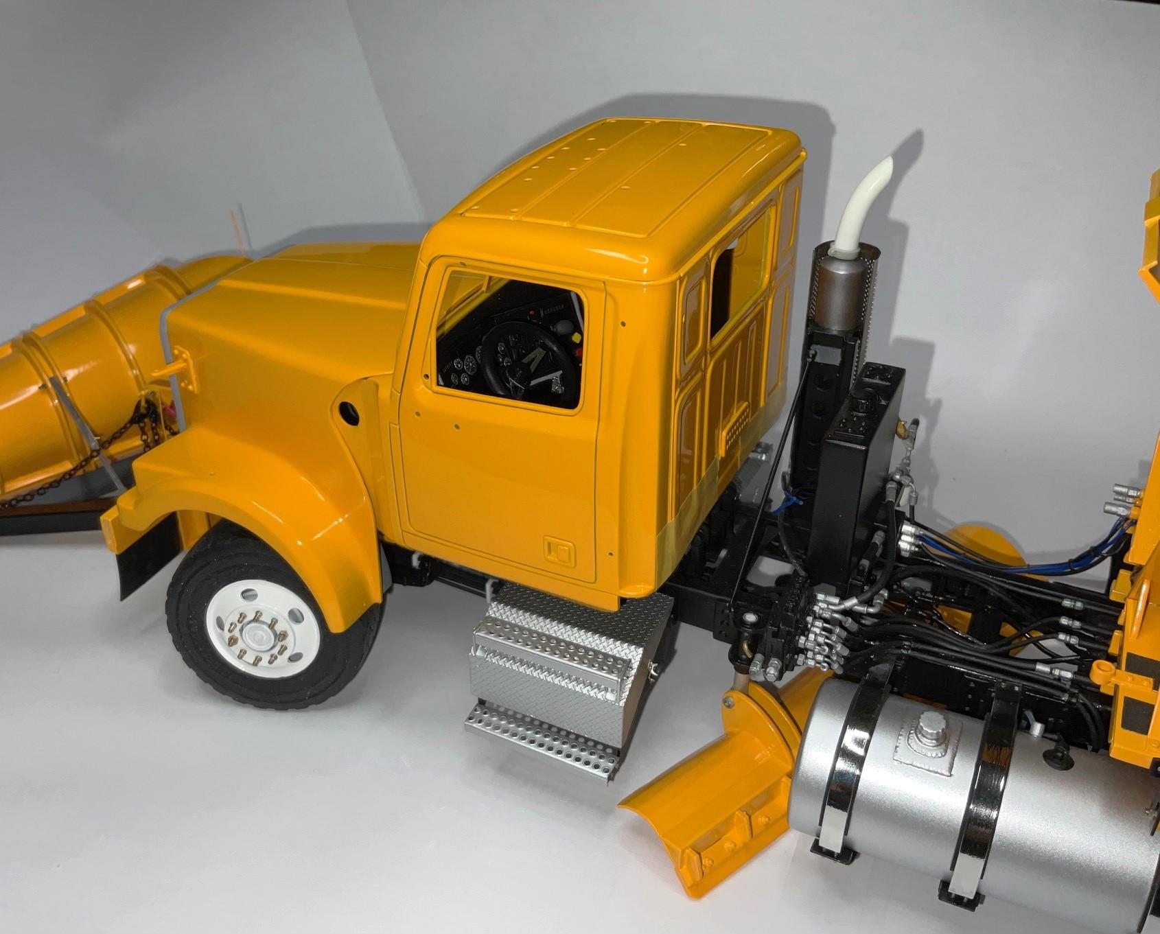
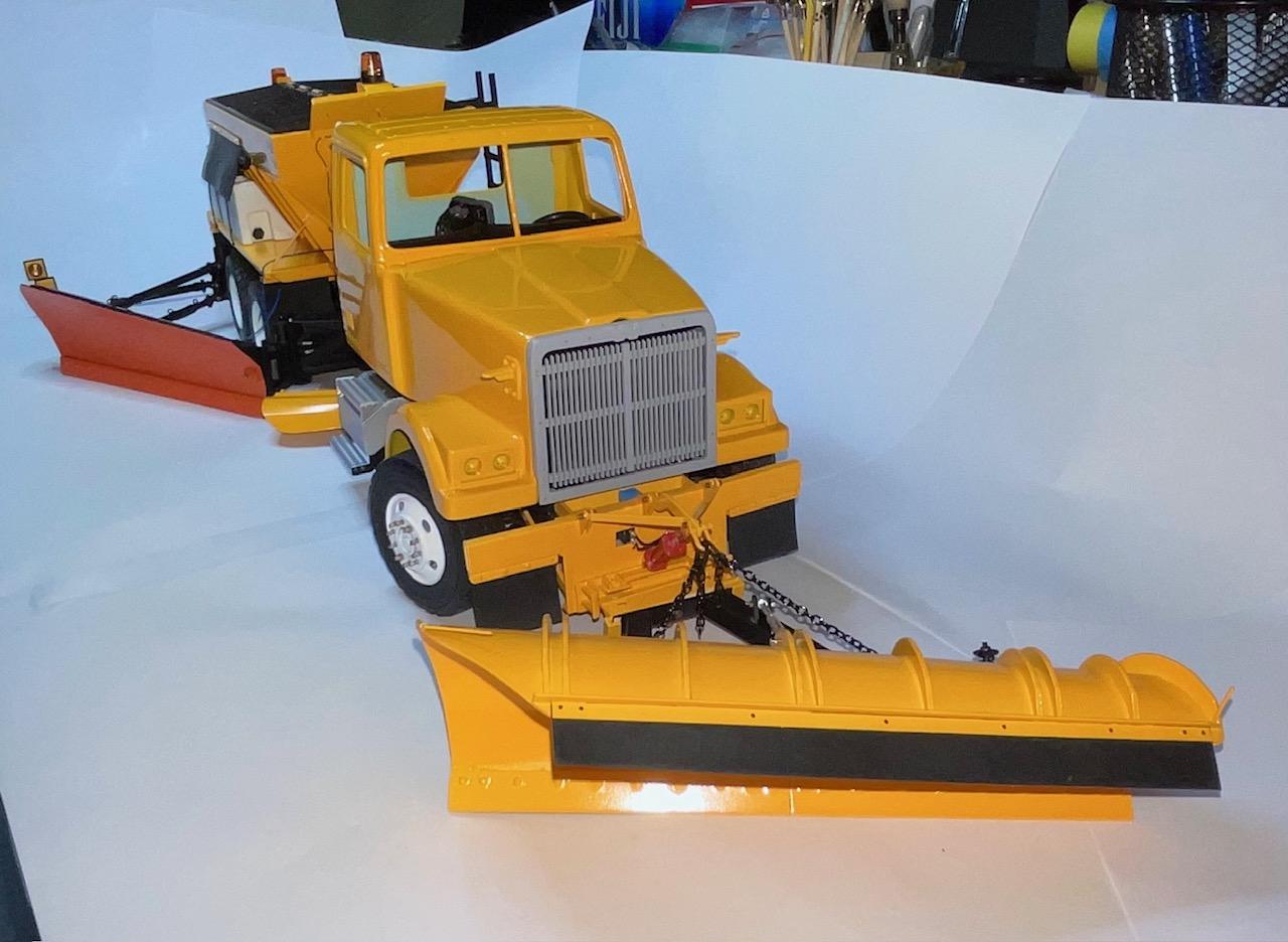
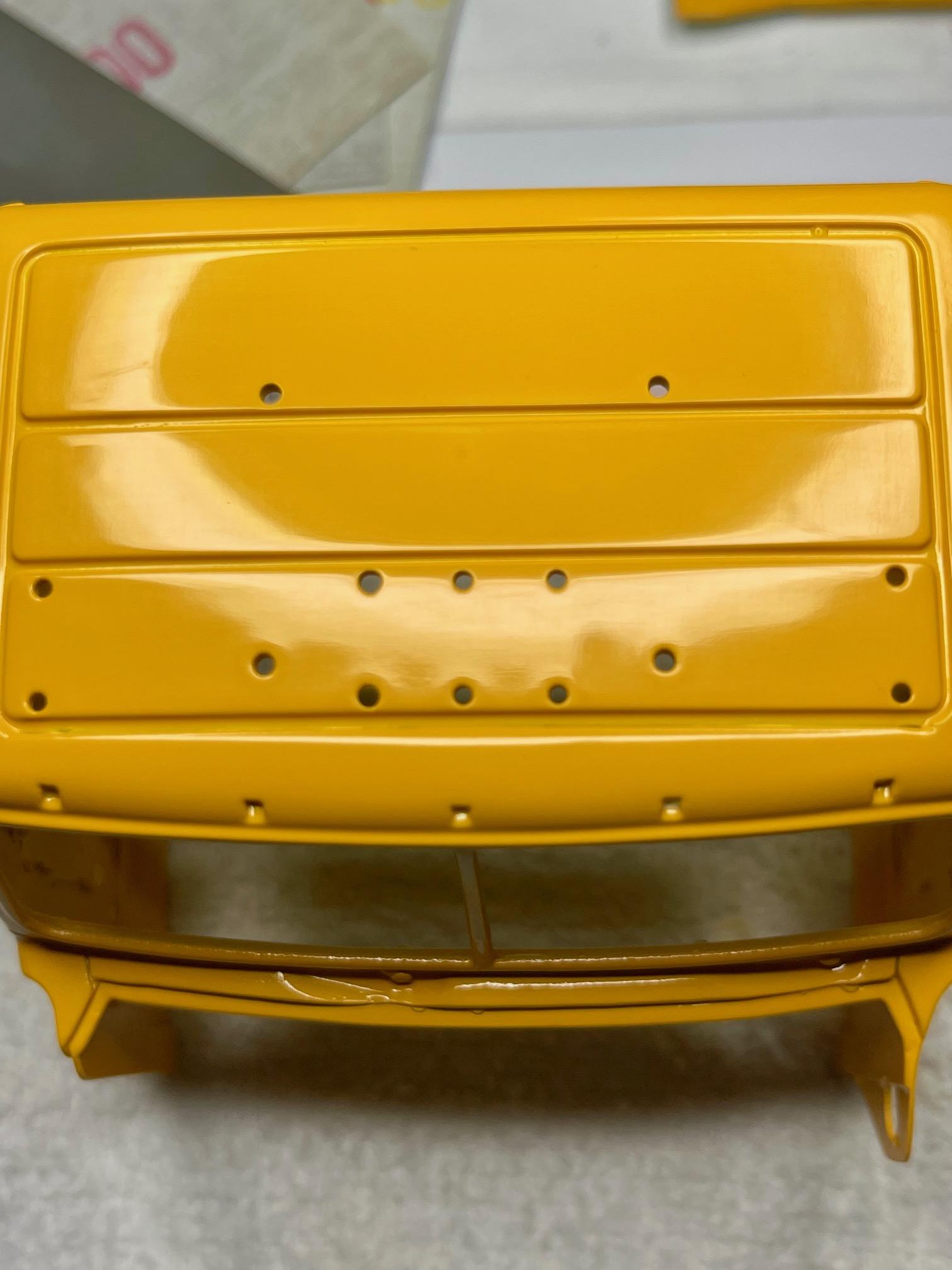
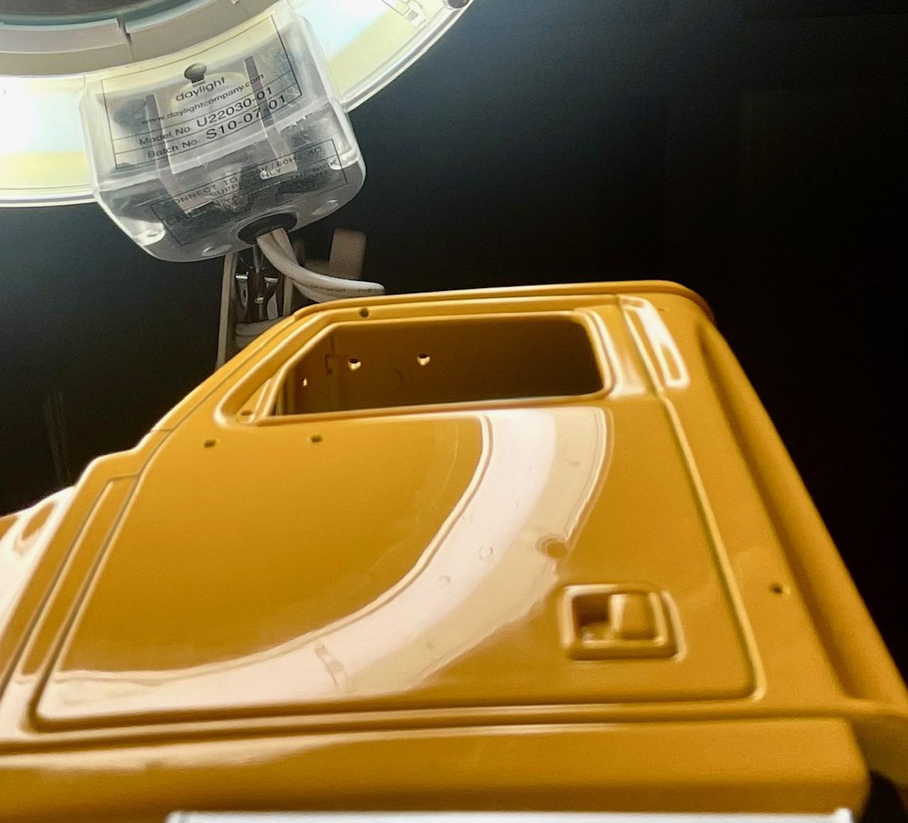
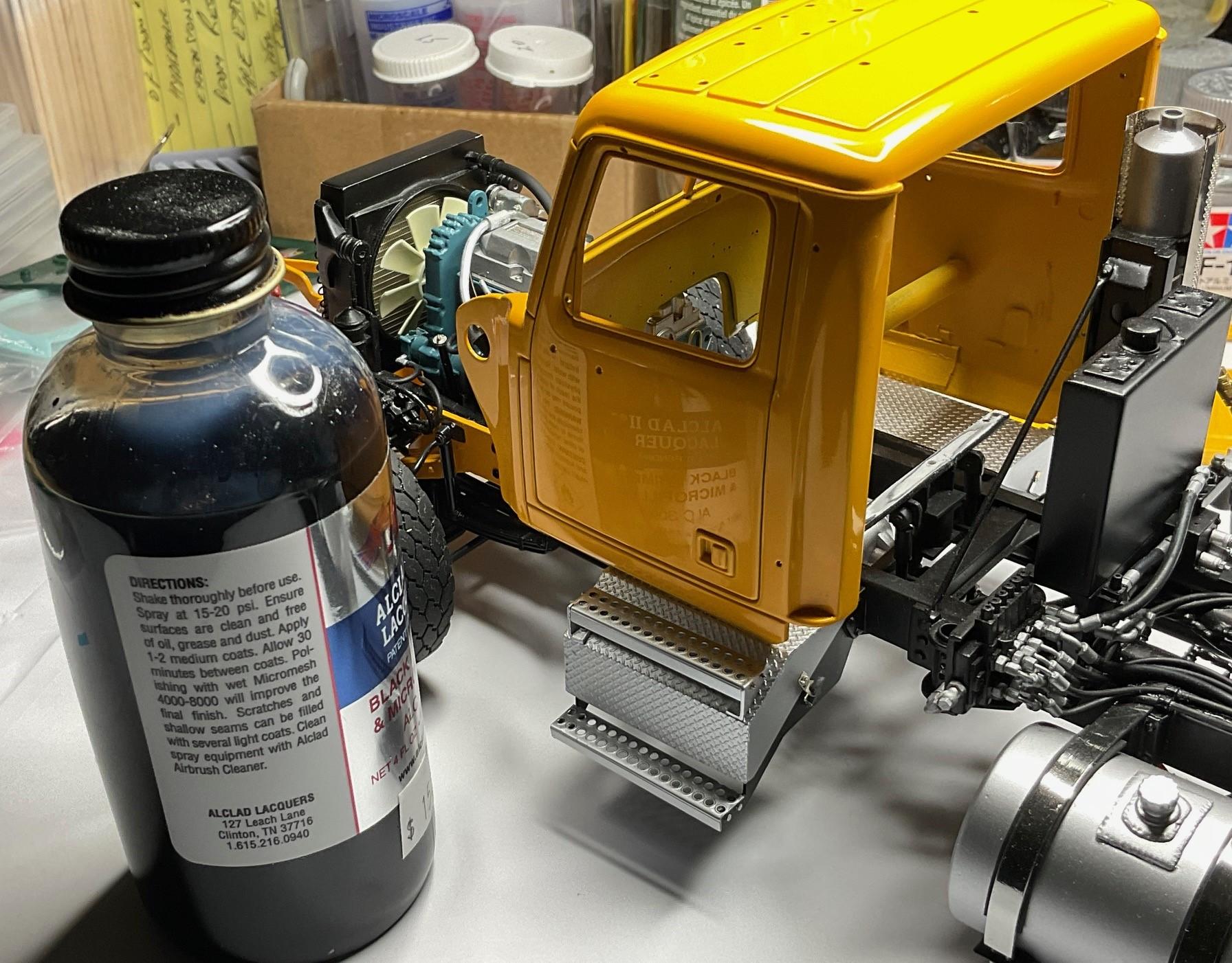
I did get a start on some polishing today, starting with the cab - figured if it messed up, it would be the easiest to re-paint if needed! Never having done polishing, apart from the test hood I did a few days ago, I had lots of fingers crossed when I started in. It's not quite as reflective as the real truck's cab finish, but best that's going to come from my bench today! This pic gives an idea of the real truck's finish - it was brand new at the time of the pic - I've got lots to learn about polishing, but I'm pleased with how the cab turned out - Hard to see in the pic, but through the polishing, I discovered a 'fish-eye' in the middle of each door - guess when I glued the temporary brace inside the cab, I used too much glue and sunk the plastic a bit. They wouldn't sand out all the way, but not going back now. . . I'm hoping the hood's finish turns out like this, too. Then, lots of detailing to be done - mask and paint rubber seals around windows, mask and chrome the door handles, finally make the air cleaner, and get on with assembling all the little parts for the hood and the cab, installing the interior, and doing the firewall wiring. No shortage of stuff left to do, but every day is closer to completion!
-
Western Star 4900 FA plow truck
BK9300 replied to BK9300's topic in WIP: Model Trucks: Big Rigs and Heavy Equipment
I'm thinking you're not giving yourself the credit you are due - pretty awesome scratch building going on in your thread! Thanks, Tom. -
Western Star 4900 FA plow truck
BK9300 replied to BK9300's topic in WIP: Model Trucks: Big Rigs and Heavy Equipment
Well, then, it's settled - no Professor for me! -
Service Truck Kitbash
BK9300 replied to PHPaul's topic in WIP: Model Trucks: Big Rigs and Heavy Equipment
I agree with Gary - good to see your progress on this! How are you finding the Fusion Chrome to work with? -
Kenworth W-925 (mild custom)
BK9300 replied to Gary Chastain's topic in WIP: Model Trucks: Big Rigs and Heavy Equipment
I’m confident you’ll get it to your liking - looks really close right now. -
Kenworth Hustler garbage truck
BK9300 replied to Rbray47's topic in WIP: Model Trucks: Big Rigs and Heavy Equipment
Very precise work, Randy, and the cab looks amazing in primer! -
Freightliner FLC
BK9300 replied to Jürgen M.'s topic in WIP: Model Trucks: Big Rigs and Heavy Equipment
Making good progress, Jurgen! -
Link-Belt HC-218 Truck Crane
BK9300 replied to redneckrigger's topic in WIP: Model Trucks: Big Rigs and Heavy Equipment
Pretty darn impressive, Tom - even more so, once attached to the rest of your model! -
Western Star 4900 FA plow truck
BK9300 replied to BK9300's topic in WIP: Model Trucks: Big Rigs and Heavy Equipment
‘In for a penny…’, I guess - thanks, Steve! -
Farm Floater Truck 1/24th scale
BK9300 replied to Randy D's topic in WIP: Model Trucks: Big Rigs and Heavy Equipment
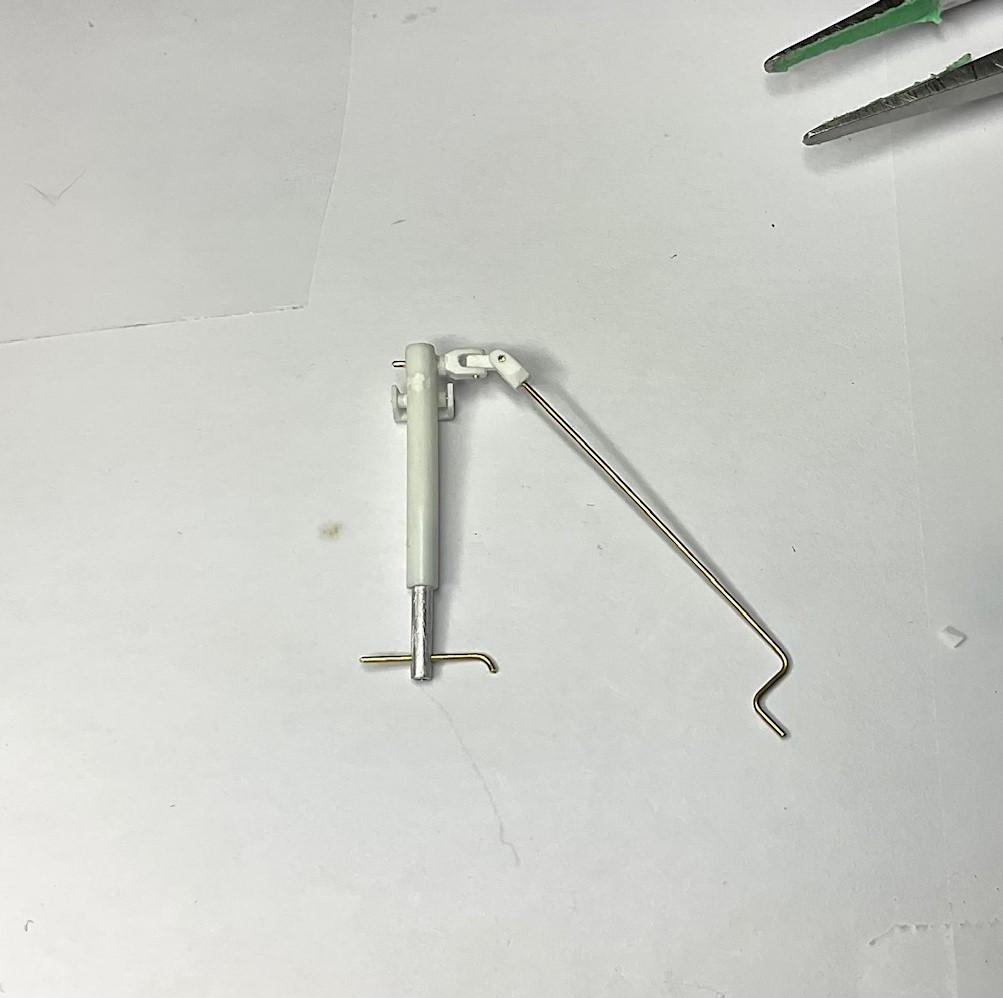
Wonderful work, Randy! I note those mechanical lever arms in the close up pics of the hinging section of the sprayer bar - I have a few of those to make next build, too. More to learn about! Always look forward to your updates. -
Western Star 4900 FA plow truck
BK9300 replied to BK9300's topic in WIP: Model Trucks: Big Rigs and Heavy Equipment
Thanks, Jurgen - don’t think I could fit tutorials into my day! Thanks a lot, Daniel! The black does sort of tone down the size of the u-joint, and that’s a good thing. -
Western Star 4900 FA plow truck
BK9300 replied to BK9300's topic in WIP: Model Trucks: Big Rigs and Heavy Equipment
Not sure about the professor - I hear student’s protest a lot these days! -
Western Star 4900 FA plow truck
BK9300 replied to BK9300's topic in WIP: Model Trucks: Big Rigs and Heavy Equipment
Very generous comments, Gary - thanks! -
Chuck Samuel's 65 El Camino (NMCA fastest street car shootout)
BK9300 replied to keviiin86's topic in WIP: Drag Racing Models
Excellent work! -
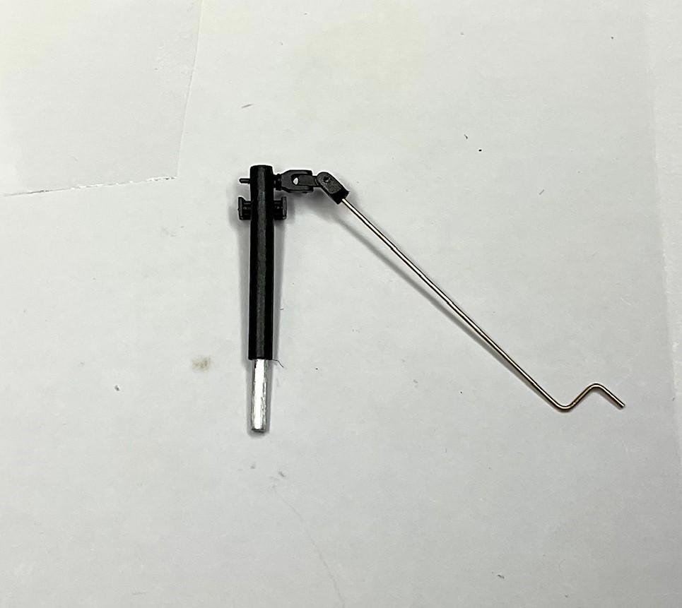
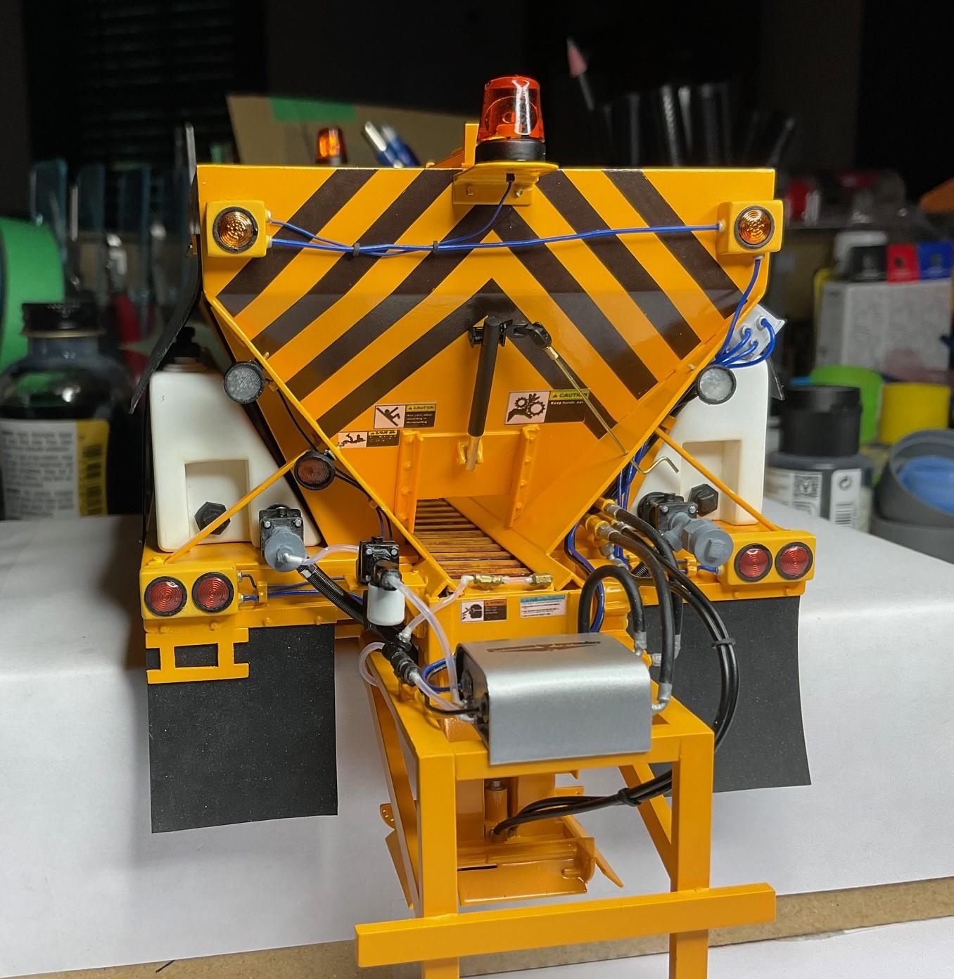
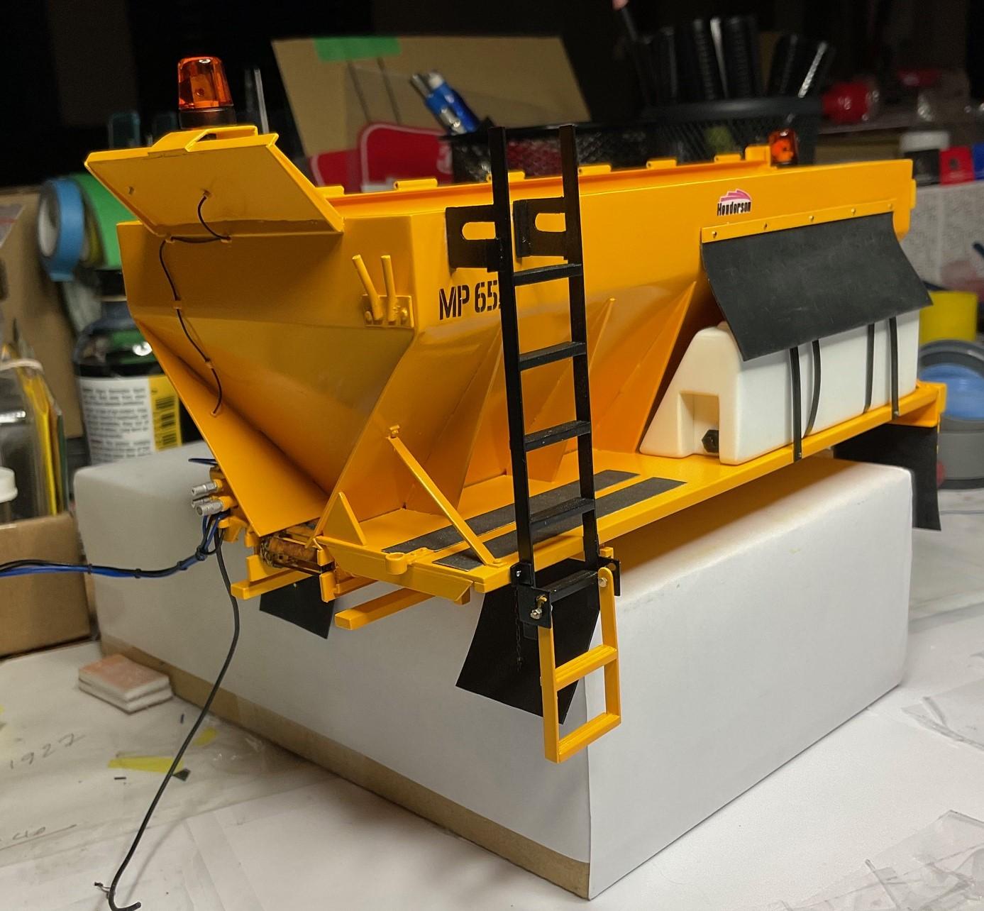
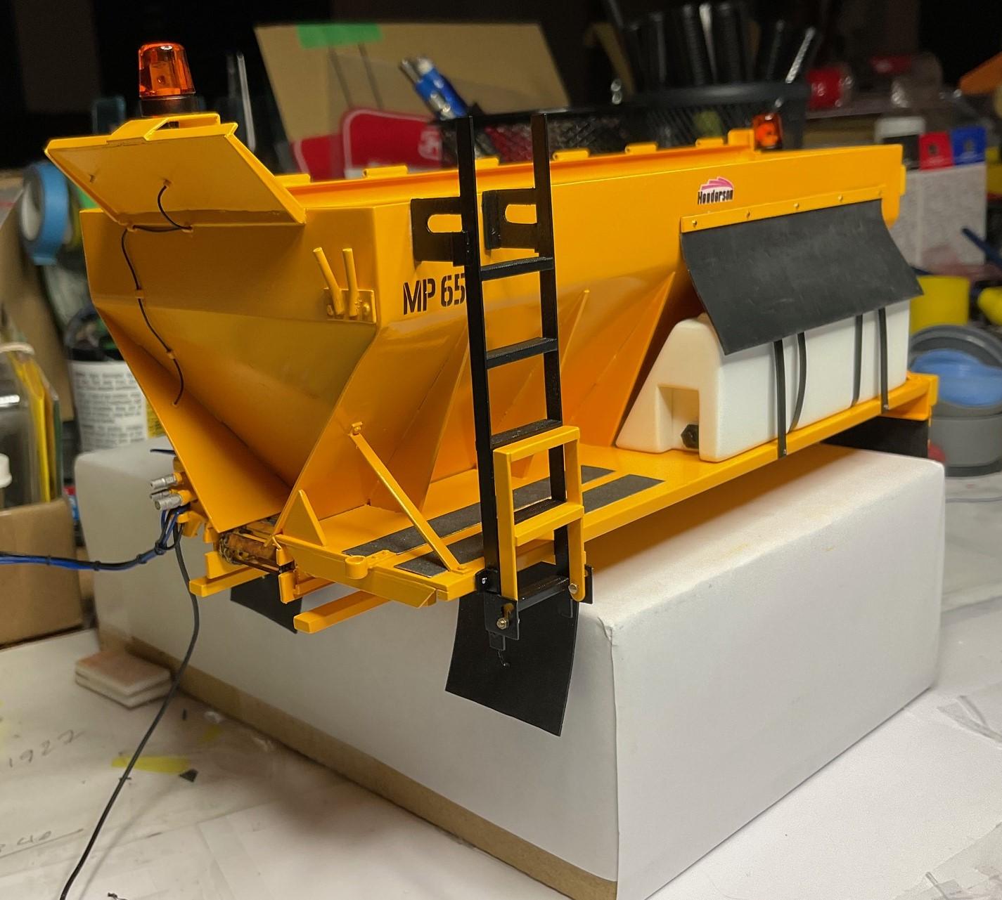
Western Star 4900 FA plow truck
BK9300 replied to BK9300's topic in WIP: Model Trucks: Big Rigs and Heavy Equipment
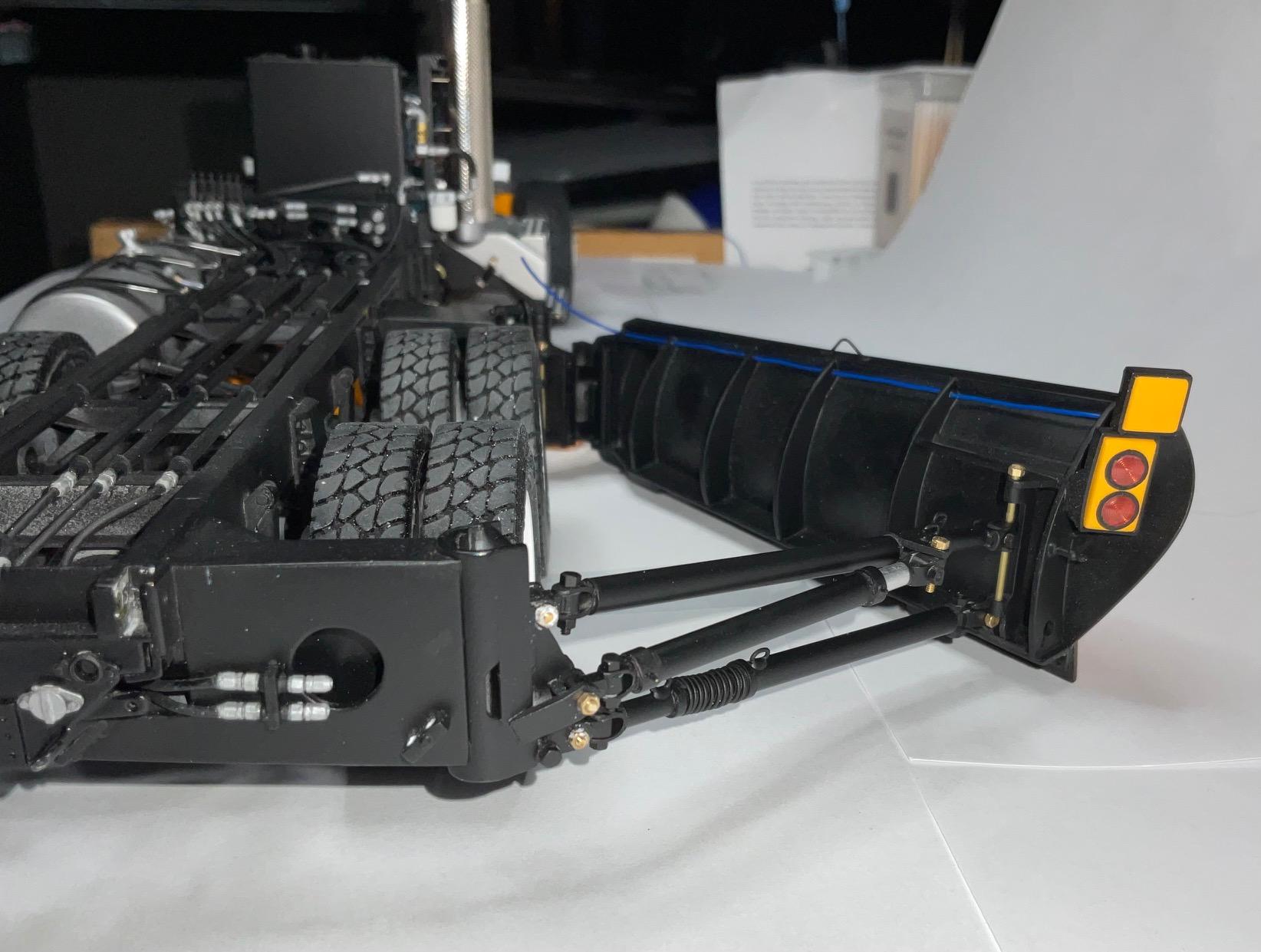
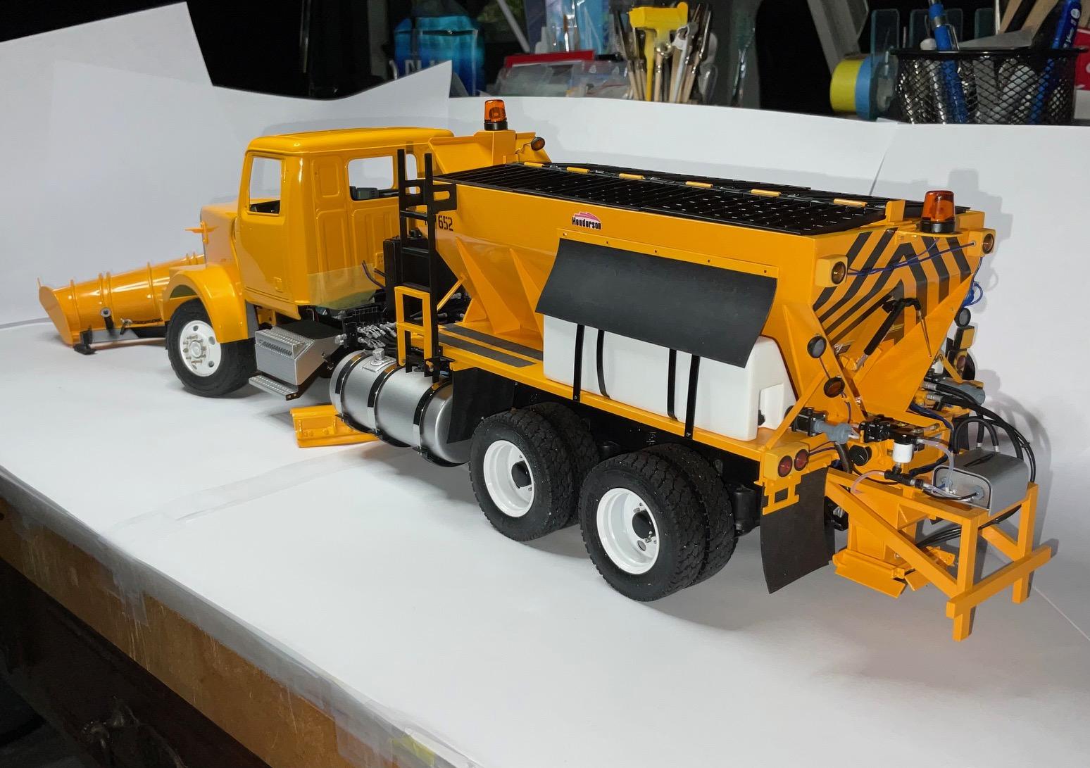
Milestone day - apart from attaching the sander to the truck frame, I'm calling the sander finished! This little item was 4 hours worth of effort - I think the universal is big for scale, but I'm confident I couldn't have made it smaller! Cylinder, hand crank, glued in place - Ladder glued in place and functioning - Won't put the screens back on top until the sander is mounted on truck. Now, I can get back to the cab and hood polishing. I promise, no more pics of the sander until it's on the truck!