
Scott Colmer
-
Posts
1,665 -
Joined
-
Last visited
Content Type
Profiles
Forums
Events
Gallery
Everything posted by Scott Colmer
-
 Excellent work on the louver press, Daniel. I really enjoyed watching you figure this one out. Definitely an idea I'll have to steal one day! Fantastic! Scott
 -
Hello from Far Northern California
Scott Colmer replied to 2doors3pedals's topic in Welcome! Introduce Yourself
Welcome back to the hobby, Dave. I used to live in Sacramento many years ago. I really liked it there. Scott -
JT, Kurt, Jeff, and Brian, thanks for the encouragement! Francis, I agree, Pinning scratch built pieces is cleaner and it also helps keep things in alignment for item interplay and less surprises during final assembly. My second choice is liquid tape, but it is messy. Here is where I am today: I've got the firewall made and pinned. The front and rear doghouses are made, but the front still need to be trimmed up. I have a question into Louie on rounding the corners on the front doghouse. Waiting for a response. The challenge was figuring out how it went since I never saw the pieces in place. I finally figured out that there is an inside dog house and and outside dog house on either side of the firewall. Louie conferment this. Here are the pics I used and then the near finished pieces. Next up is the interior hardware. Louie made a custom chain drive transfer case to move the steering column to the right about a foot. I remember it and had one picture of it. You can also see s foot bar and a brake pedal. Here is the transfer case. I'll add bolt detail after it is painted. I wanted to capture the chain drive even though it will be barely visible. The solution was to find the best chain drive in my kits (mini bike from the Vandal) and cast it using silly putty for a mold and my two-part resin. I was getting ready to make the brake pedal when I noticed the the roll bar was not true in a couple parts. The passenger upper hoop was out of alignment as were the two rear frame extension. So this morning I have been prying the connections apart and correcting the alignment. I can't figure how I let that stuff go in the first place. I also had to relocate the steering box back into the firewall so it will line up with the transfer case. Thanks for looking and commenting!
-
64 Dodge D100 Pickup Pro Street
Scott Colmer replied to AmericanMuscleFan's topic in WIP: Drag Racing Models
Those rear suspension shots are MONEY! I had to run through them a few times. I especially like the peek under that back of the bed. Great work, Francis! -
This is amazing, Mark. You execute every small detail perfectly. I am really enjoying this! Scott
-
What ELSE did you build? Non auto related.
Scott Colmer replied to Scott Colmer's topic in The Off-Topic Lounge
Time to dig up this old thread to celebrate a major completion. Four years ago, when we had to pool remodeled, we ran a gas line for a fire pit. I stacked up extra sticks in a circle around the stub that was sticking up out of pool pavers. It sat like that for three years. But, I had a plan. First I had to build the curved planters, then get the dimension of a curved couch. For there, I could place the fire pit. I officially started in July. I get the design approved by the accountant and general approver, Nani. Then I cut a big hole in the pavers. The first step was to make a template out of paper. I placed it on the ground in front of the couch and then found center. I used a hammer drill to put a small hole in the center paver and drove in a nail. From there I tied line to it and drew a circle sweeping around like the hands of a clock. Checked to make sure it was even, and got out the DeWalt angle grinder and started cutting. I ended up using that angle grinder to cut A LOT of bricks for the inlay surround and the column and the capstones, which are made of the pavers I took from the big hole I cut. The most fun was figuring out how to cut square pavers into pie shapes that fit together. I finally figure out to go back to finding center. This time I used wire instead of string so there would be no stretch. I laid up the brick and used one wire for the outside cut and one wire for the inside cut, The long wire was also used for angle of the side cuts. Also fun was when a good friend came and helped me build the column. The bricks are vertically stacked because to did not wand the point of the side sticking out. An inside row of cinder block to support the burner and bricks on top of that ensures strength. I almost blew on the placement of the control panel, (too high) but I caught it in time and the fix was minor. Anyhow, it's done, I'm happy with it, and the Approver is very happy
-
Baby Driver was a surprise to me. I thought it was going to be just a chase movie, but it really had a lot more. Very good! One to skip - Gemini Man with Will Smith. Bad: Script (predictable), directing (how many close ups of people talking to the side do we need?), acting (Like they were all on a Zoom call not wearing pants.), and CG (A little less than Call of Duty story line sequences.) Watch I am Legend instead. Scott
-
64 Dodge D100 Pickup Pro Street
Scott Colmer replied to AmericanMuscleFan's topic in WIP: Drag Racing Models
Excellent work, Francis! Both the distributor and four link are works of art. Very clean! Scott -
Hey JT and Francis, thanks for the interest and encouragement! Just a few littles this post. First is creating the snout on the end of the third member. I could not find a pic other than the one I had. I couple of modelers tried to help, but nothing there. I did appreciate the help! So I just made it symmetrical and went with it. Next is the trans crossmember. I never saw the one for the 1:1 truck, so I made a simple one trying to fabricate in a style consistent with Louie's. It's held in place with pins. Now a fix. When I made the main part of the firewall, I found that the the driver's side of the body leans in just a bit at the top. That was a by product of cutting the body apart and widening it to make it to scale of the 1:1. If you look, you can see the front door frame leaning lower than the back. The fix required slicing the body along the towel and carefully bending the body back into alignment. I filled the gap with chunks of plastic which I later ground down smooth. I was bummed to see it was wrong, in the first place, but I was glad I caught it before I got to paint and the doors would not close evenly.
-
There it is. Thanks for posting the pic, George. I looked all over the net and could not find a pic with that snout. I figured that it had to be cast for more strength, so I felt it would be safer to make it symmetrical.
-
Thanks again, George. I glued up the snout this evening. I'll post a pic after it dries and gets trimmed up. Scott
-
Good call, George. I found a bunch of them on the web, but I still can't find any pics of that extra part on the snout.
-
I need a little help from the Big Rig experts. I am trying to replicate the snout of this third member. It is probably a Peterbuilt item, but I am not sure. I have this pic. I need to see the other side too. Any ideas would be greatly appreciated. Scott
-
Guess I'm on a roll. Here is the battery and air tank taped in place. And here is the scratch-builtfuel cell in place. It's pretty large because Louie talked about running the truck up Pikes Peak. Fixing the dog chew was a lot easier than I thought it would be. That pretty much completes the bed. The firewall is next. I will send these pics off to Louie to see if has any changes.
-
Hi Daniel, I super glued a small disk of Micro mesh sanding cloth to the end of styrene rod of the size impression I wanted. I trimmed it close with an exit blade. The grit was maybe 1000? You can see the rod in the picture. The soft backing of the sanding cloth provided just enough give. Experiment and count the turns to get a consistent pattern. I did have to change the disc from time to time. Hope this helps. Scott
-
Hey Daniel, I've been following along and I have to say this a fabulous build. All the extra detail is fantastic. You were asking how to get and even pattern on scale engine turning. Here is a pic of my solution. The trick is to hold the turning tool steady and move the surface being turned.. I made the jig in the picture. It keeps the rod with a piece dot of cloth sand paper glued to the end from walking. The surface is ducting tape. It takes the pattern very well. I tried this process with bare metal foil, but it turned the foil brittle and it chipped when it was installed. Scott
-
Quick update. The optima red top battery is done. The Battery tray is done. I only had one pick of it and no measurements, so I eyeballed it. The air tank is done. The mounting bracket is in the works. Both the battery and the air tank are going to hang off the back of the rear frame crossmember.
-
Thanks for the comments, Jeff and Francis! I've following your Pro-street P/U, Francis. Amazing. Louie gave the grill the mark of approval, but said it looked a bit thick. I'll flat-sand the face of it and the inside edges later. I made some bits and pieces progress. Here is the radiator. It's a heavily modified kit peice based on custom truck radiators found on line. The PE radiator pattern looks best over a solid color. So the background will get some flat black later. This is the in-progress battery tray that Louie made. Louie told me it would mount in the rear. If he does not come up with a place, I'm going to hang it from the rear crossmember along with a small tank for the airbags. It would have been A LOT easier if he did not drill all those holes in it. The plastic is thin sheet. Harder to work with, but now that I know Louie is watching that, I'll do my best to stay in scale. Finally, the Exide Red Top battery in progress. I chose this one because the internet said they can be used for Diesel engines. I'm using an internet pic as a construction guide. Next is to repair the fuel cell try that my doggy chewed off then make a fuel cell. After that, the bed work is done and its on to the interior. The last phase will be finalizing the engine. I have very little idea how the pieces should go together. Thanks for looking. Scott
-
MCM Relaunch Update, 27 Oct 2020
Scott Colmer replied to Dave Ambrose's topic in Model Cars Magazine News and Discussions
Wow. That first cover looks great! Hats off to the team the put this together. I look forward to buying that issue and many more! -
Wing or foil shaped styrene rod
Scott Colmer replied to Scott Colmer's topic in Model Building Questions and Answers
Thanks to Gerry helping me out with the wing-shaped rod I needed. The grill for Louie's truck is finished as per his instructions. -
Thanks for the comments Bob and Francis. This project has been a bit of s slog for me. Your encouragement helps a lot. Time for the grill. Louie wants 14 wing-shapped bars. That put me on a quest to find wing-shapped rod. It's just not out there, easy to find. I found out a company in England used to make it, but that was 10 years ago. When, and if, it shows up on eBay, there is usually a bidding war. So I checked with the MCM forum community and Gerry (Exotic Builder) had some he was willing to part with. Many thanks to Gerry. Great guy. I made the grill shell a while ago based on on the was laying the the cab of the truck last time I saw it. I found some styrene strip the was the same thickness at the wing-shaped rod. That will help wit the spacing requirements Louie called out. The it was a matter of cutting a bunch of little spacers to glue in-between each grill bar. A perfect job for my Micro Mark chop cutter. Then it was a matter of starting at the top of the inside shell and working my way down. The bars are not held in place by glue; they are trapped by the short square pegs of styrene. All the bars are in place. The bars were held together with a strip of right angle styrene glued down each side. Now it can be removed and chromed with Alcad. It presses very snugly back into the shell. And there it is on the truck. Radiator is next. I have some PE radiator mesh to add the right look. Scott
-
I finally got the under chassis exhaust on the FXI hot rod truck made and hung.
-
Francis, thanks for the encouragement. I'm still plugging away. It was time to finalize the exhaust with hangers. First, I had to pin the bed, which I should have done a long time ago. The location points match where Louie put them. Look at the far front and back. The rear is is a slip fit and the front is a pinned bracket. With the bed secured, I could place the twin rear tips. But first I had to make the exhaust hangers. I had some experience with this from working in my Pop's muffler shop as a summer job. The frame mounts a pretty sturdy because I felt that the under chassis system would be pretty heavy. The frame mounts are pinned so they can be removed and painted separately. The thick disc between the frame mount and pipe bracket will be the rubber biscuit that will flex and absorb vibration. You can also see the flex/expansion pipe sections that Louie put in the design. I made those be wrapping wire around exhaust size styrene and then cutting and gluing each ring free and flattened it so it would be straight and not look like a coil. Finally, it was time to add the dual pipe tips out the back. I had a great idea to line the up with the 59 caddy taillights Louie had installed. Then while I was falling asleep one night and building the truck in my head, it occurred to me that the heat from the unmuffled exhaust would possibly melt the caddy taillights. CARP! I decided to let it go. Then when I was checking my work, I realized that the bed had slipped and the tips were hitting bottom of the bed. I had good reason to cut the tips free and move them towards the center of the tailgate. Yes, the exhaust runs under the rear axle as per Louie's directions. And there I am. All I have left are the flanges between the headers and the electronic cut outs. I'm on to the area bar grill. While the bars are drying, I'll be sand the under exhaust smooth. Scott
-
What non-auto model did you get today?
Scott Colmer replied to chunkypeanutbutter's topic in The Off-Topic Lounge
Not so much a model as a sign of the times. I'll keep an open mind. So far, nothing that catches my interest. -
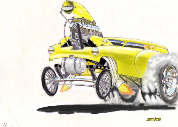
These arrived a while ago. Love those showrods. Sad goodbye to an old friend. Looking forward to the reanimation of MCM.


