Chariots of Fire
-
Posts
2,782 -
Joined
-
Last visited
Content Type
Profiles
Forums
Events
Gallery
Everything posted by Chariots of Fire
-
 WOW! Does time fly! If you had asked me when that was I would have said 4-5 years ago. But 9! Must be getting old!
 -
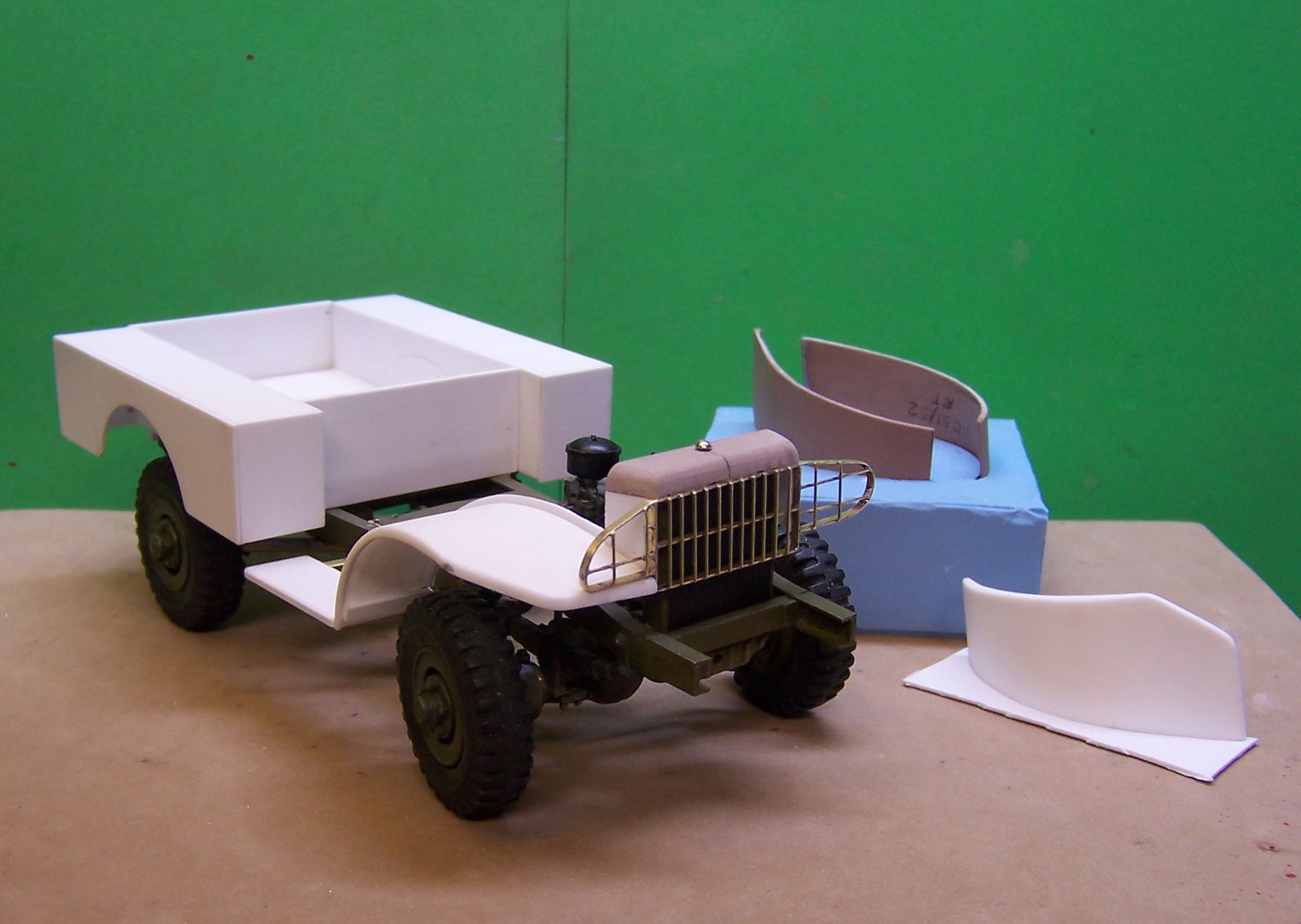
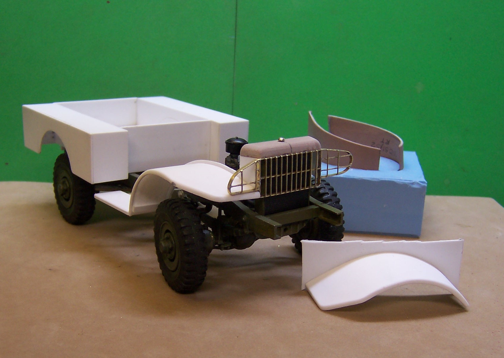
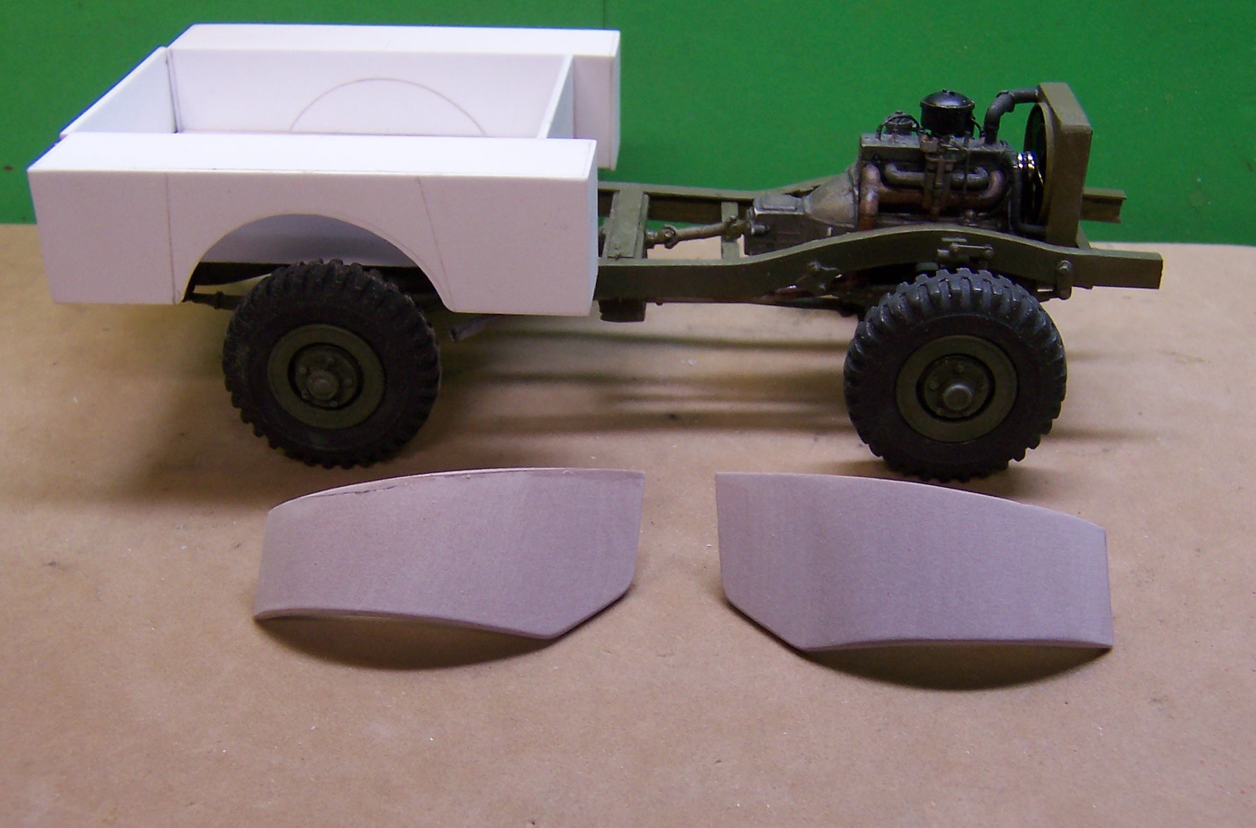
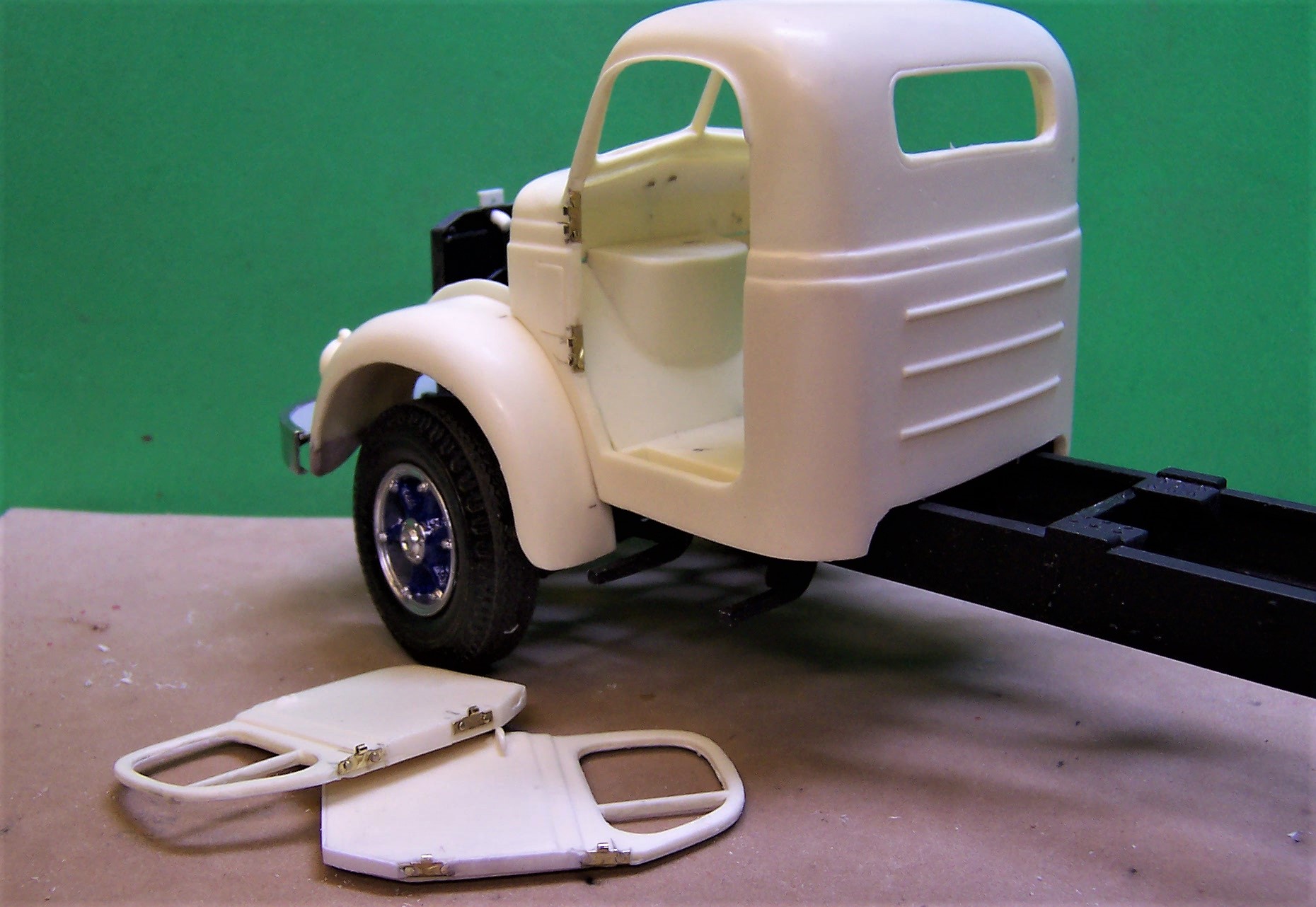
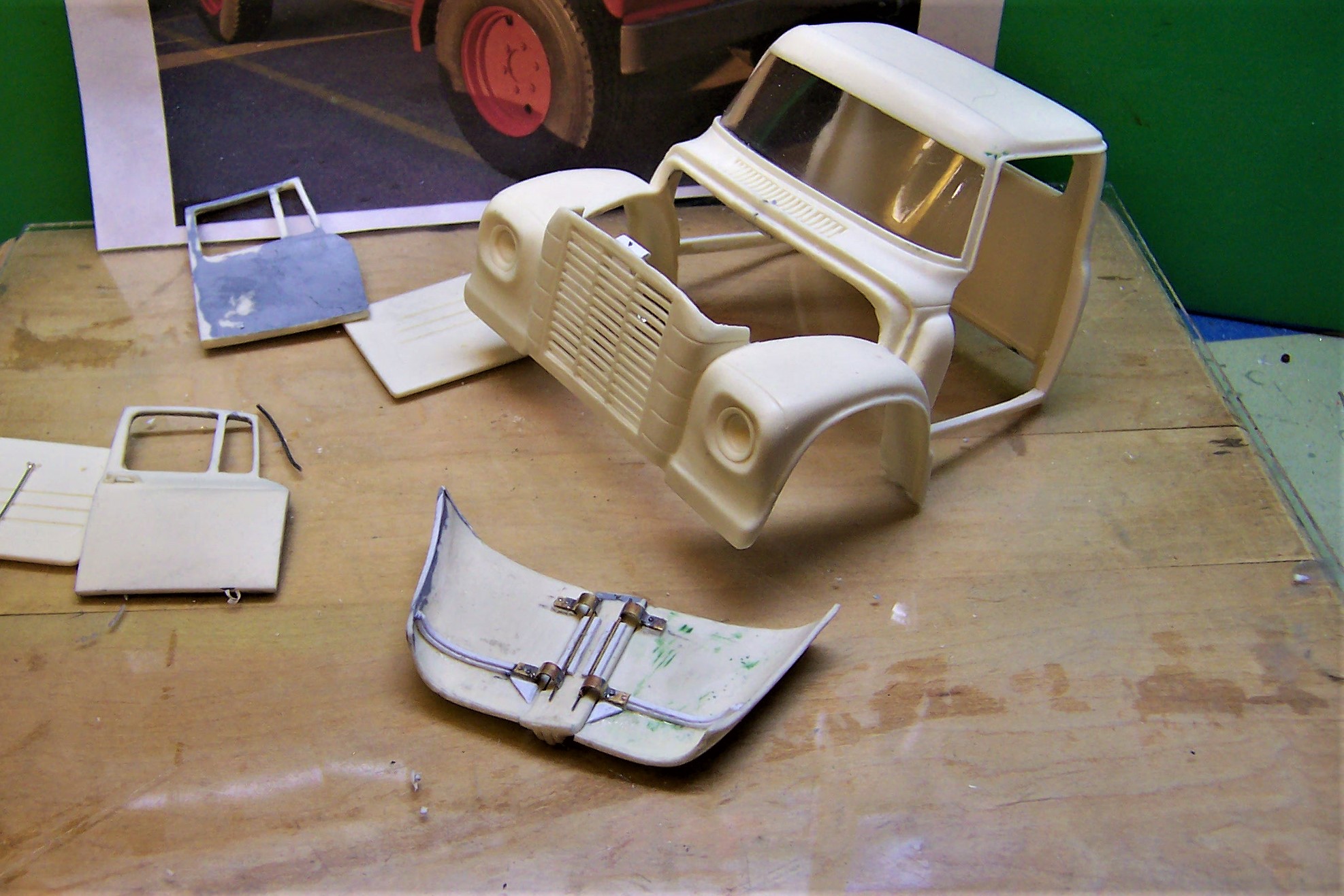
The fenders have been cast and the process of mounting them in the right place is being done. Lots of trial and error, even with scale drawings because so many different things have to match up. I did some study of the photos in the technical manual reproduction to get some information. The rest is just getting pieces cut, fit here, cut there, sand this, match that.....etc. In the background is the mold and the two Ren Shape fender masters. They were simply glued down to a flat base like the casting at the right and a box was built around them to hold the RTV. Even with the raised outer edge, the castings can be removed easily one they are set hard. It took a bit to get everything lined up. The grill guard is made of small strip brass and wire soldered together. If the winch was not part of the model the grill guard would extend down abut twice as far. But the winch and its frame do the same thing to protect the radiator from objects coming at it from the front. The fender at lower right will be trimmed as the right one that is now on the frame. Not only is it a piece of the model detail it really stiffens up the resin casting so that it will not sag. The fender has an outer edge that is thicker than the underneath part. The radiator shroud is temporarily screwed to the radiator so that things can be lined up. Once all is said and done the radiator cap will hide the screw.

-
Was that the issue that featured the USAF Type O-5 Crash Truck?
-
I'm not a good tinker, Bob! I've tried it several times, some results not so good, others ok, The most difficult part is getting the bend at the outside edges. I tried soldering a thin strip to the fender once it was curved but that meant having to bend the strip in two different directions. Even after annealing it was not easy. So I just went with what worked before. Besides I am doing two of these rigs so making a mold meant killing two birds with one stone. Or in this case casting two sets of fenders with one mold!
-
Here are the pieces carved from Ren Shape for the fenders. With this work completed the next task is to give them a coat of clear gloss to seal the pores and then they will be ready for casting. The block in the background of the first photo is the Ren Shape. The outline of the fender was drawn on one face and the fender was roughed out on the band saw. then the outside curves were sanded to the line drawn. Then the final underside was sanded out using a Dremel and sanding disk. In one fender I had to add a small sliver of Ren Shape to the inside but it is sanded smooth. It takes CA glue nicely. The inner fenders will be done separately to fit on top of the frame. Once the fenders are cast the inner fender pieces will be glued to the fenders themselves. This will strengthen the castings and keep them from possibly sagging later on although that was not an issue when I did the fenders for the Class 325's.
-
Since the last post I have made an executive decision to switch to Ren Shape for the front fenders. Having done one fender in brass the decision was easy as there is much more control over the shape. Once a set is made a mold will be made to cast two sets. One set for this one and one for the next one when it comes on the line.
-
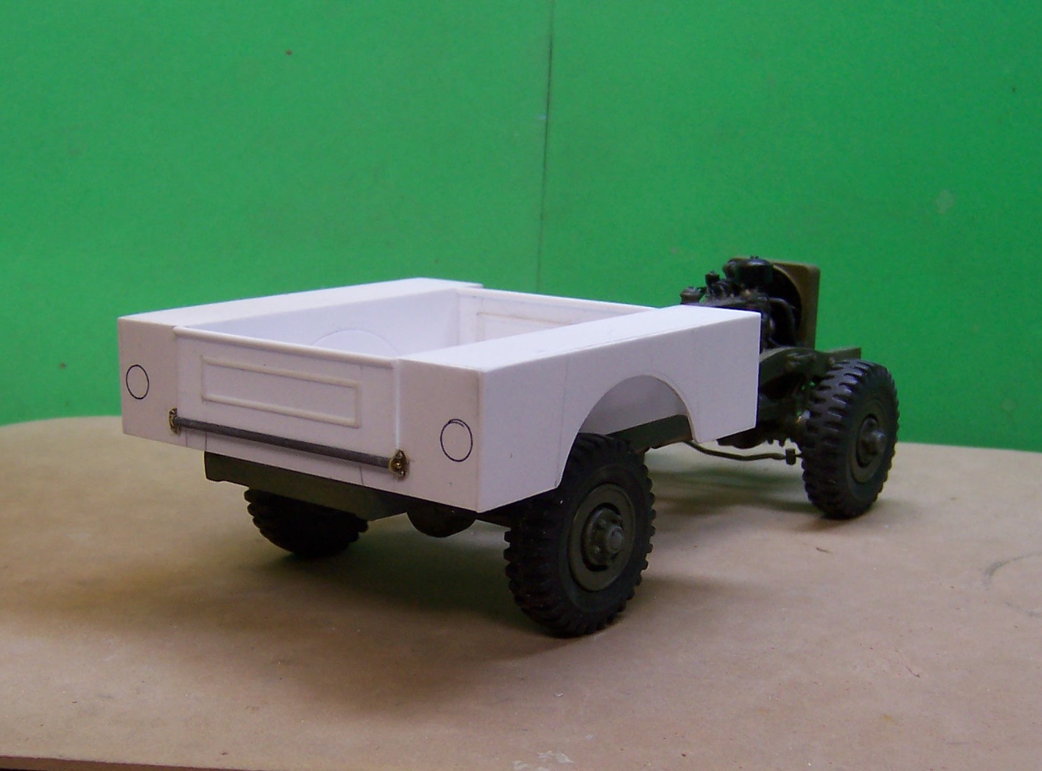
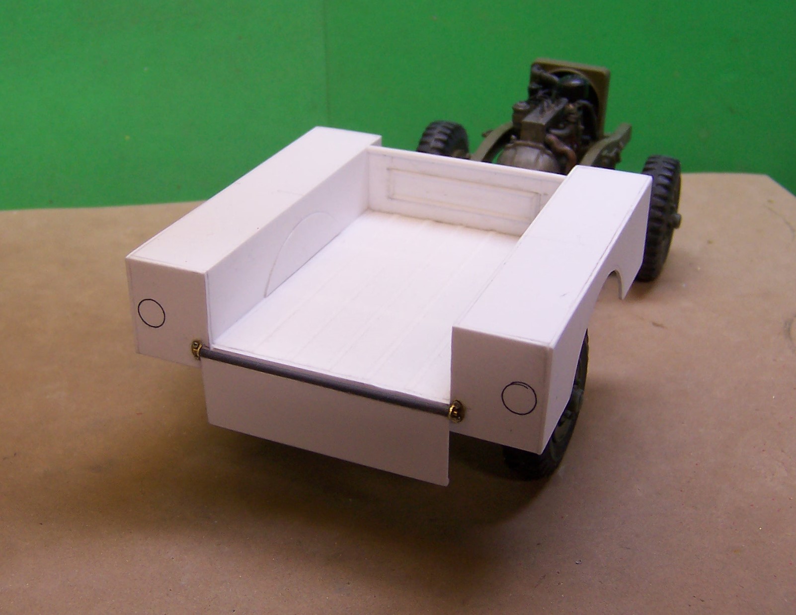
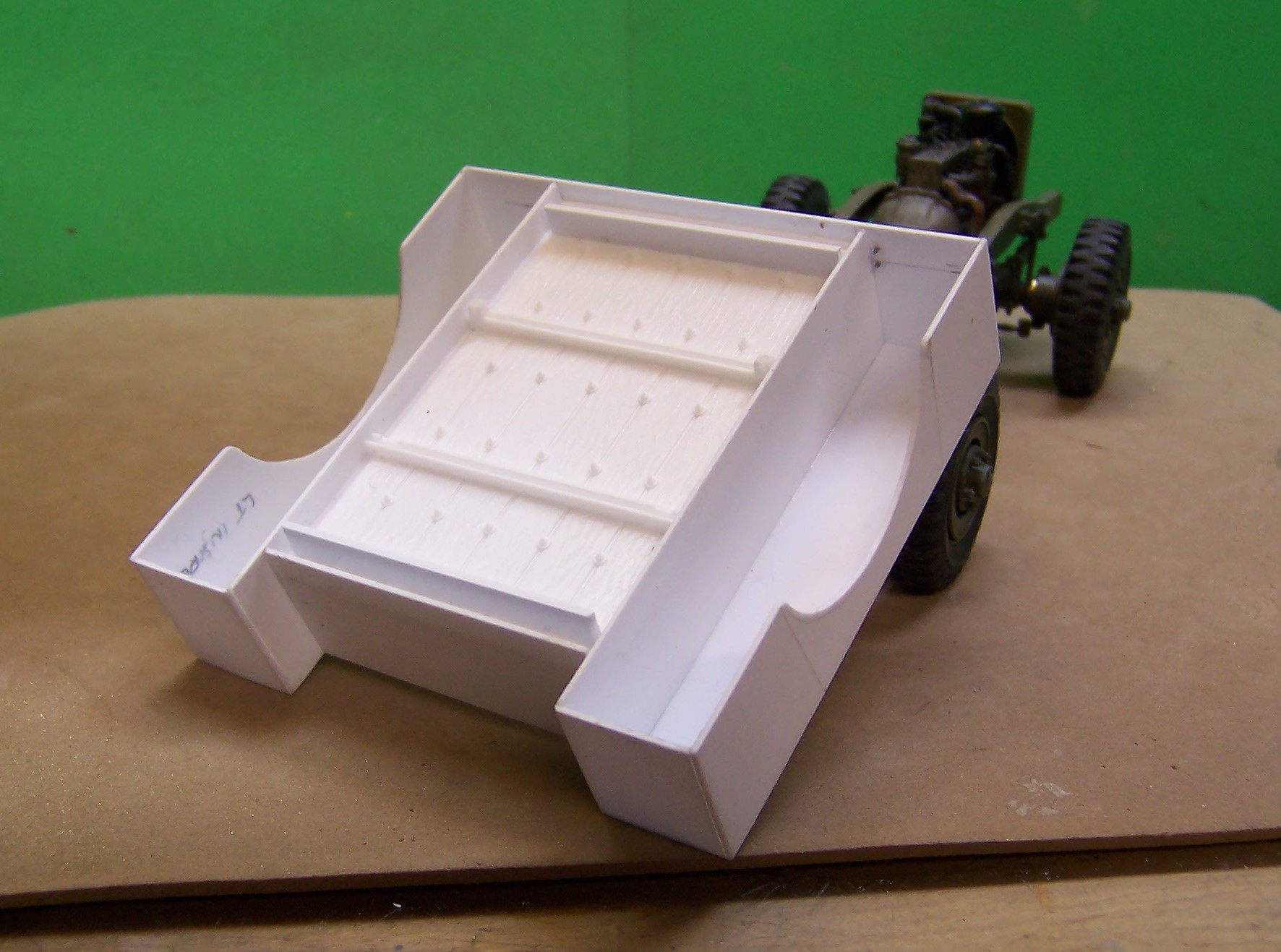
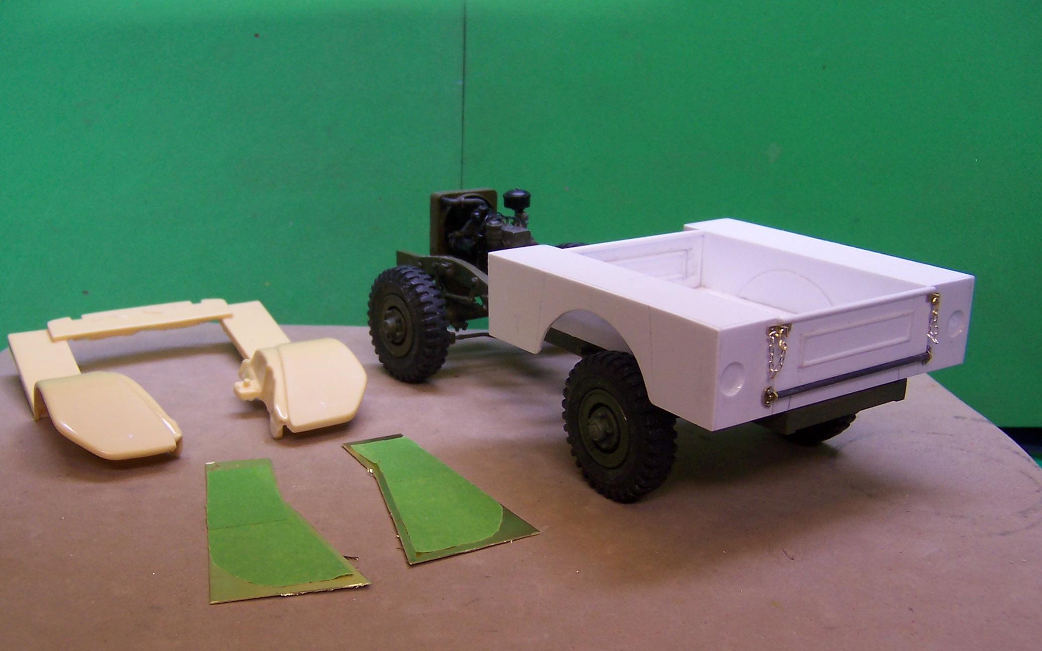
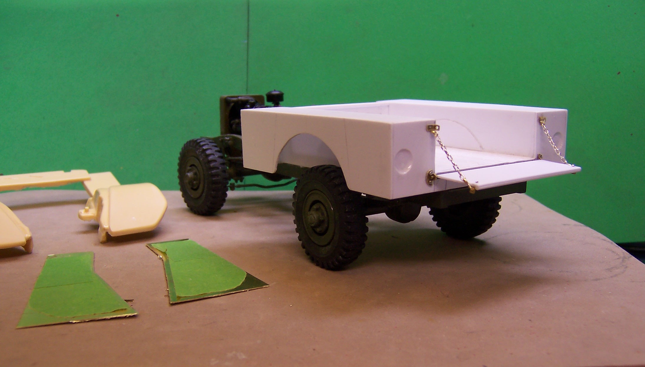
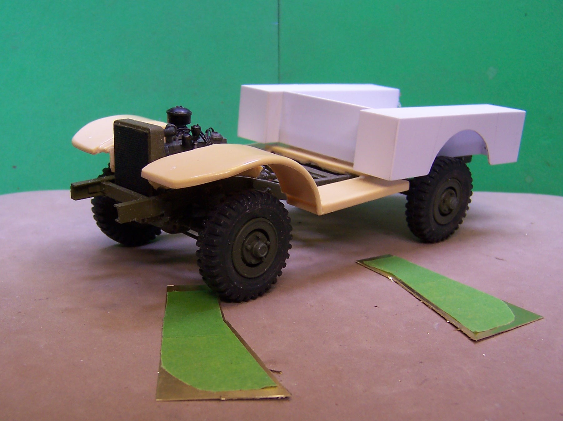
Work begun on the body. Basic construction is with .030" Evergreen stock. The inside of the bed came from the '41 Chevy pickup kit. It was exactly the right width and only needed to be shortened about 1/4". The raised center part of the tailgate and the front of the body raised portion were made using 0.040" half round stock. Small strip brass was used for the hinges and the upper latches. Each of the tail lights and side lights on the body are indented. So far the back ones were done by opening up each area and using a rat tail file to make the opening round. Then a piece of sheet was glued to the inner face of the body. Finally a drop of casting resin was put into the opening. Surface tension kept the resin up against the outer portion of the opening. When it set it looks like the edges are beveled. Now to begin some work on the front fenders. If it looks like the body is extra wide compared to the rear wheels it is. The track is only 63" while the body width is 82. Maybe in the design they were expecting to use double wheels in the back but this is how it is. The front fenders are just about the same as the Power Wagon that came out after the war. There have been several done as diecasts; Danbury Mint, Matchbox and Ertl to name a few. Below are a pair of resin cast fenders that were done using the Danbury Mint model as a master. The shape is good and surprisingly it is the right scale and width. However, I'm finding them too thick for my taste so using some masking tape I covered the surface of them and then trimmed the tape. The tape was lifted off as one piece and laid flat on some brass sheet. I'll cut the outlines, bend to shape and solder on the tapered edge. The results will be a much finer fender line.
-
The axle on the Ertl P/W extends into the brake plate and it (the end of the axle) Is split with a round nub on it. When pushed into the brake plate it snaps in place and cannot be dislodged without cutting. I tried squeezing the ends together with needle nose pliers to see if I could pull the axle free after I removed the tire but it would not budge. You have to pry the tire off the rim. After doing that the outside portion of the wheel will separate from the brake plate to expose the nub on the end of the axle.
-
Thanks, Bob. Will check those out.
-
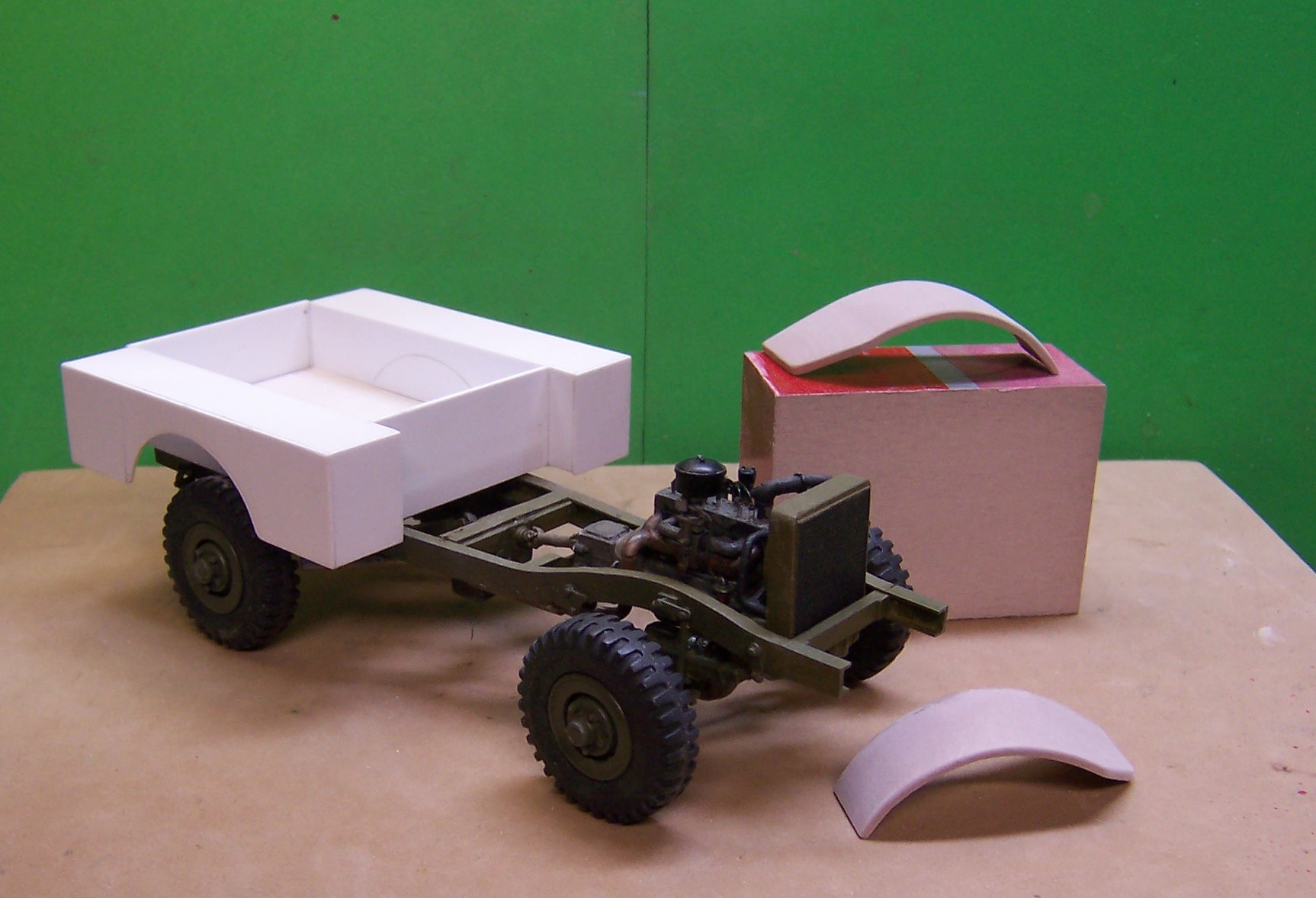
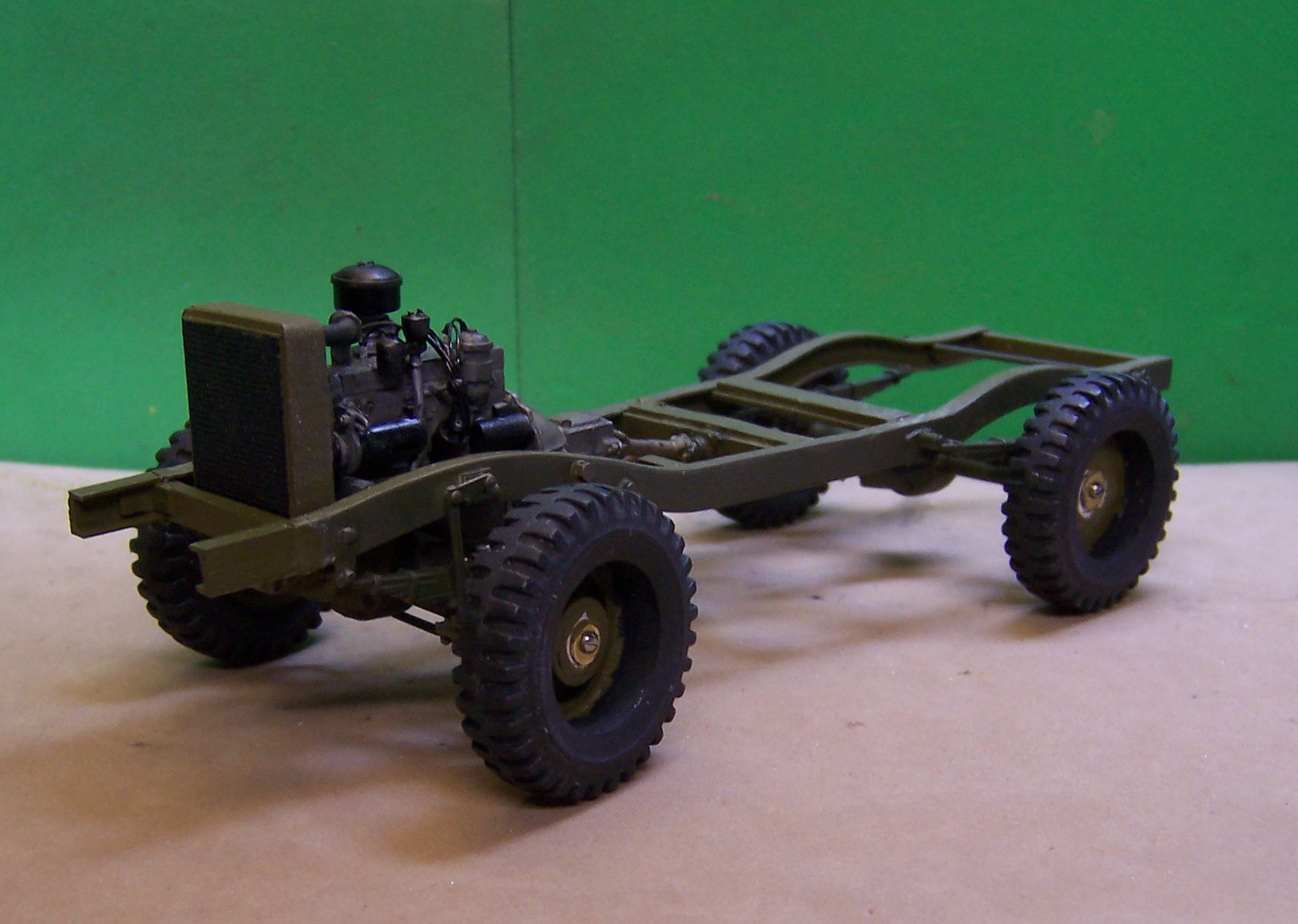
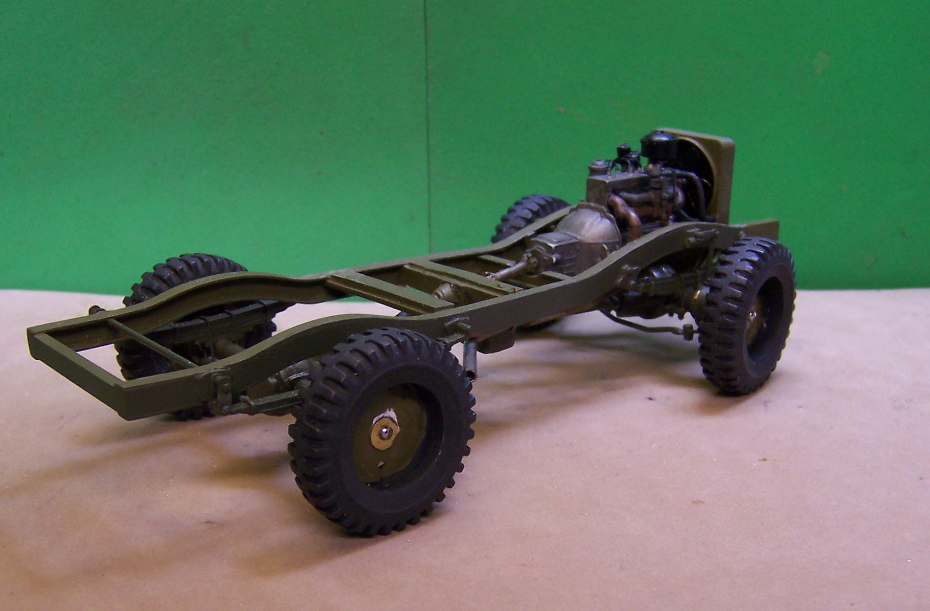
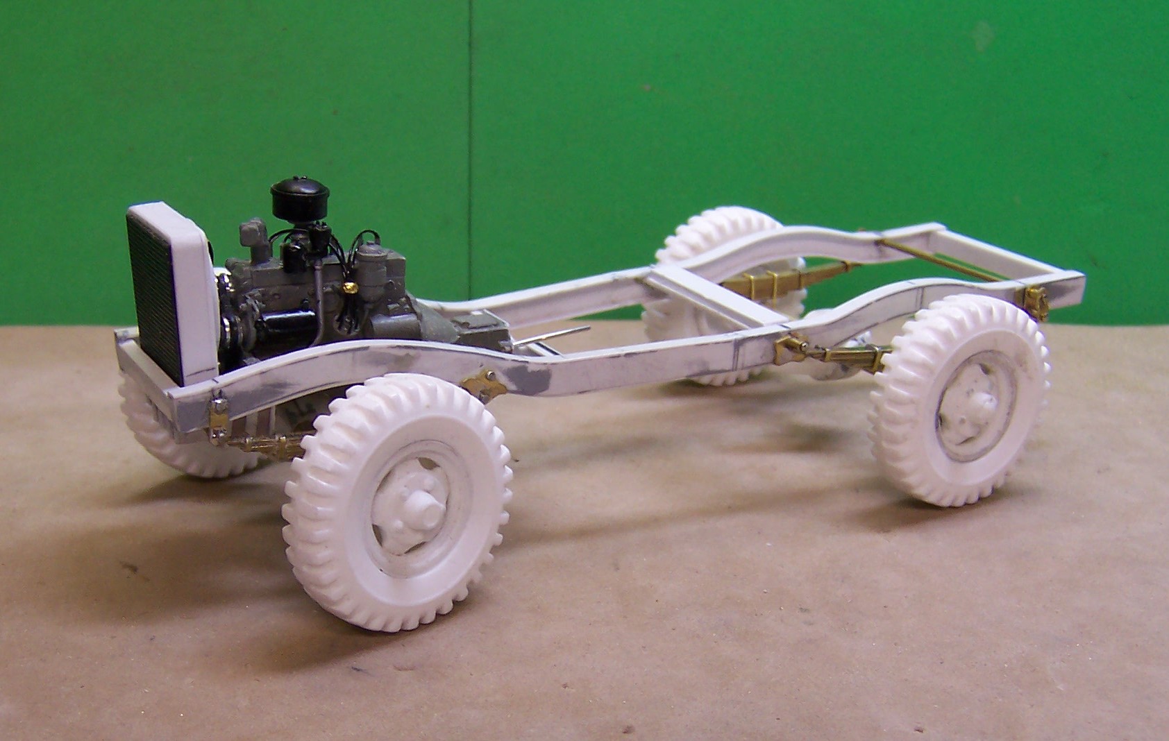
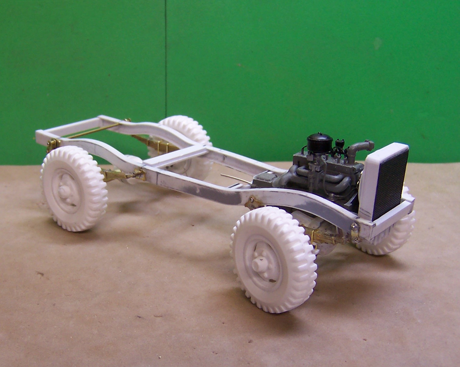
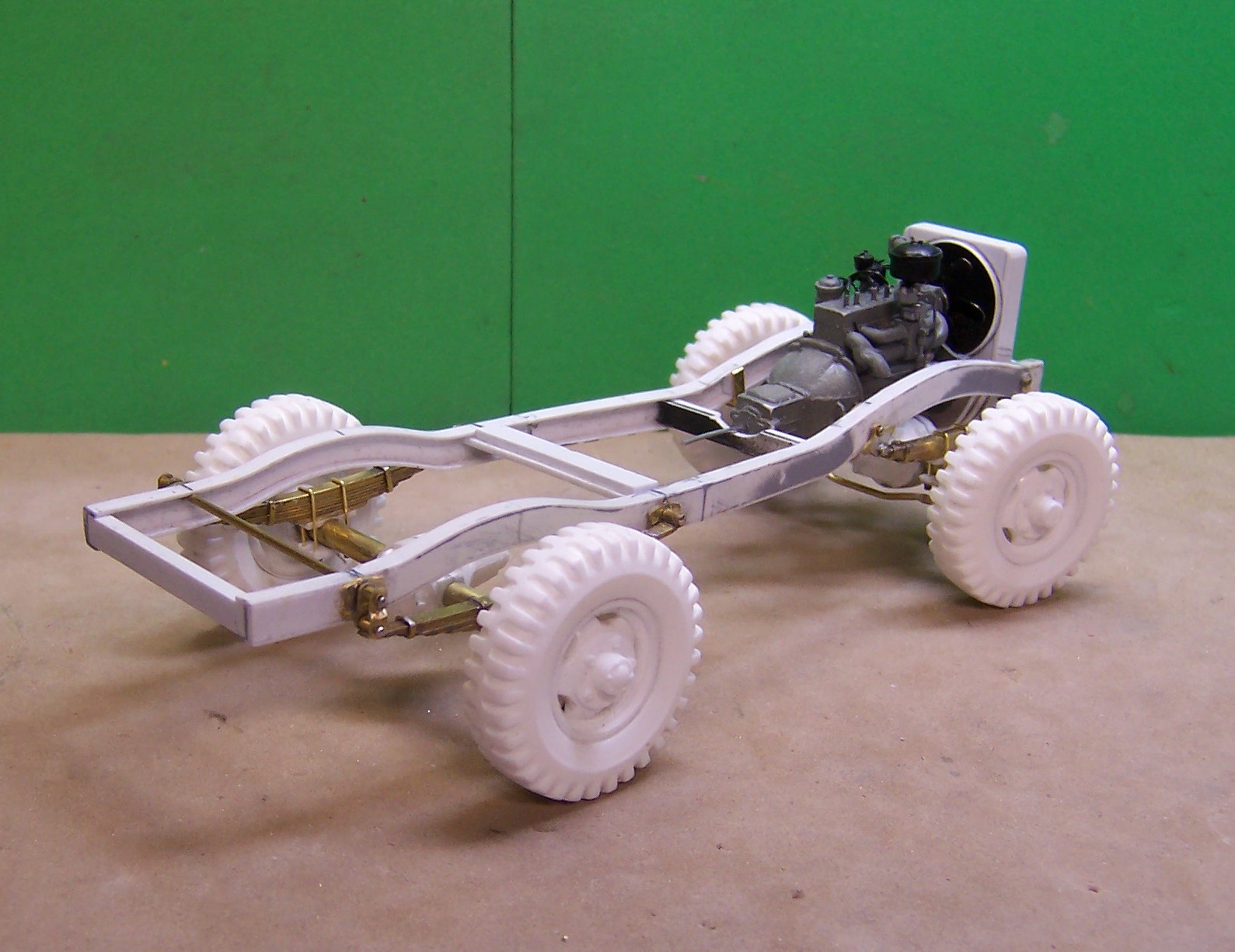
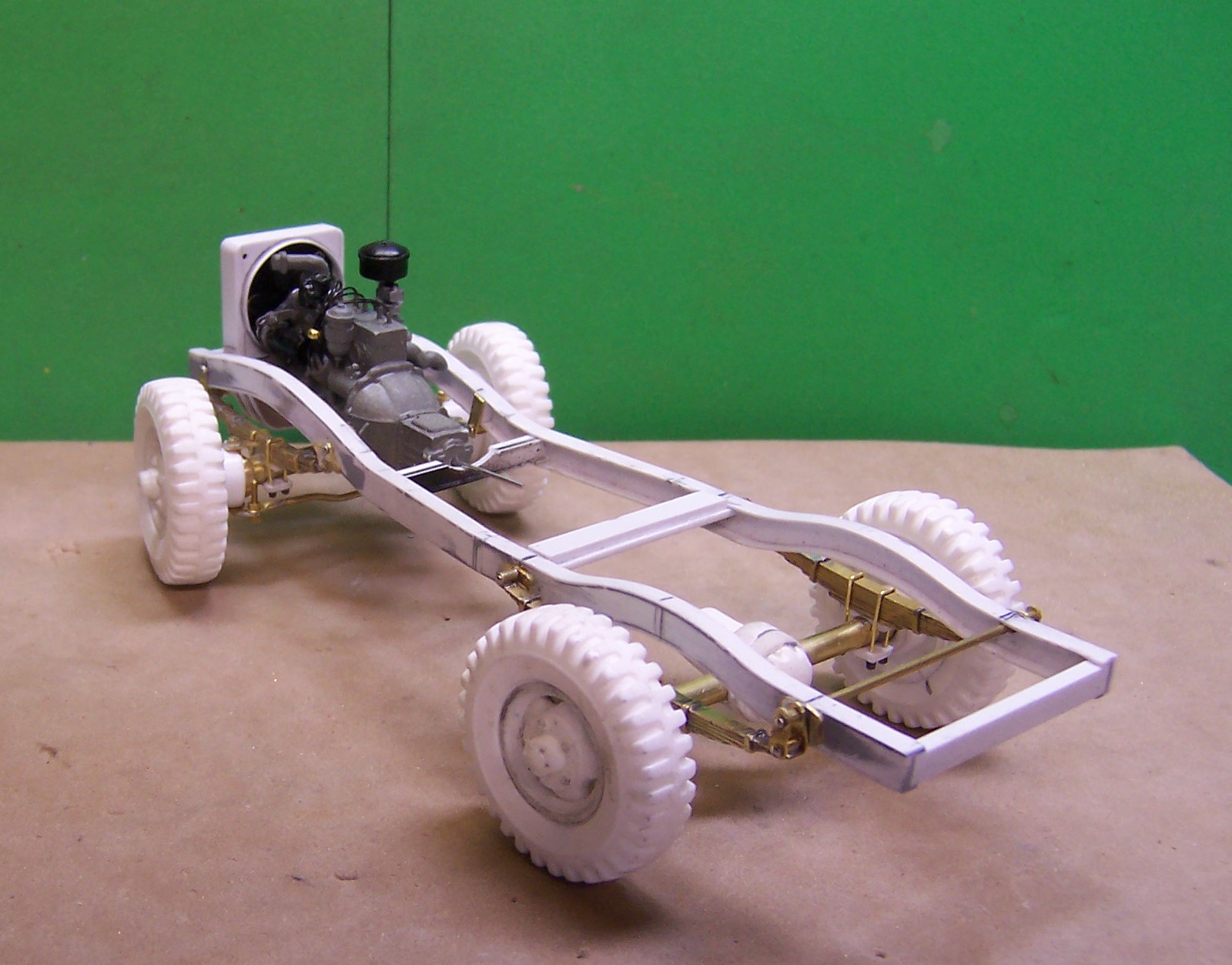
Tonite we got the last of the chassis work done. The front and rear outer wheel pieces are now ready for installation and the chassis is painted. Still having issues with trying to find a good OD color in a spray can. I may try one of the auto parts stores to see what they have. The newer model paints are too dark for this vintage vehicle. Anyway here we are to date.
-
Mack DM800 question
Chariots of Fire replied to brian falcone's topic in WIP: Model Trucks: Big Rigs and Heavy Equipment
One other thing to check. Where the ends of the axles bend upward you may have to adjust those also when you take out a section from the middle. The location of the springs is going to control how you do it. -
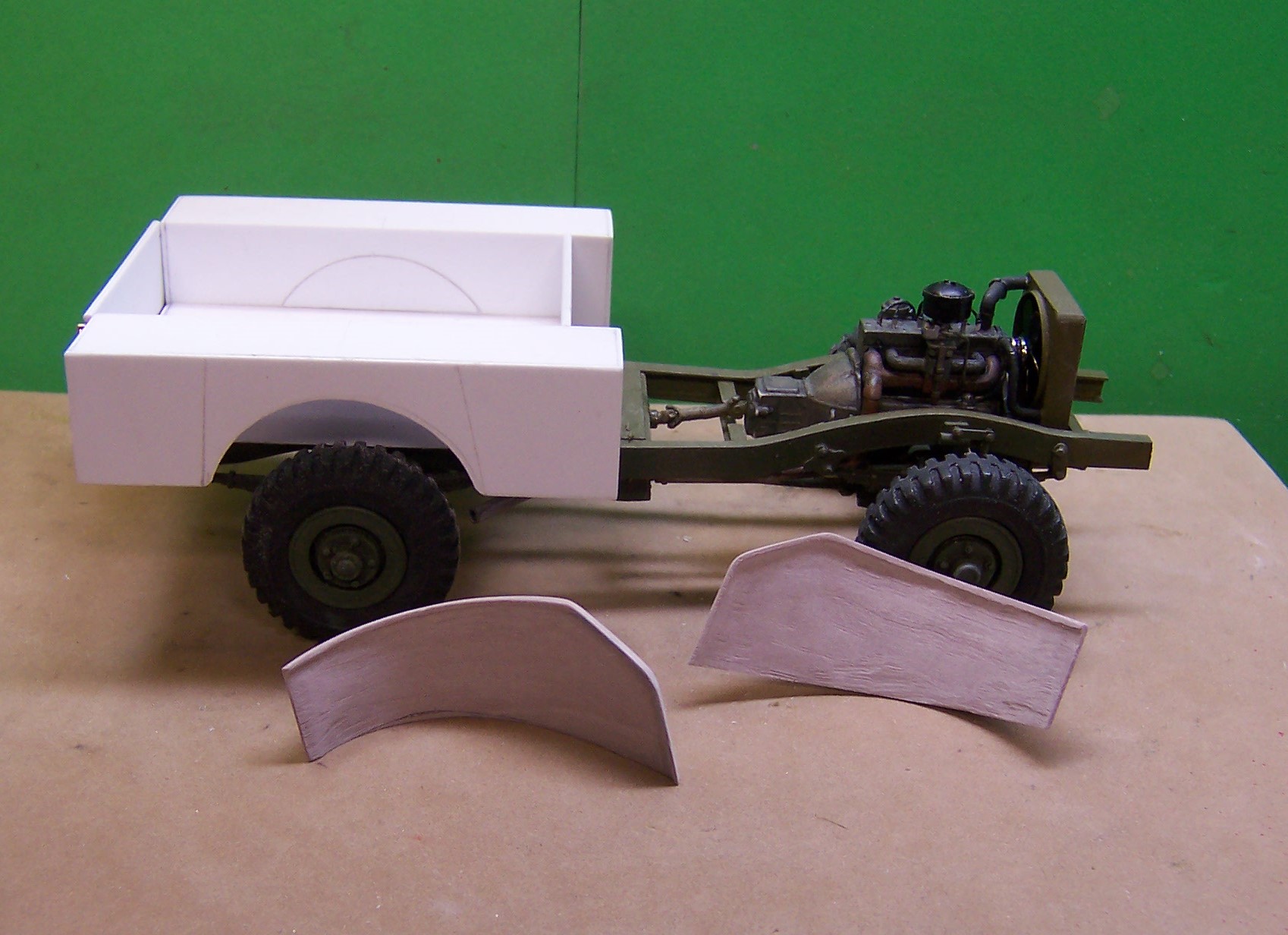
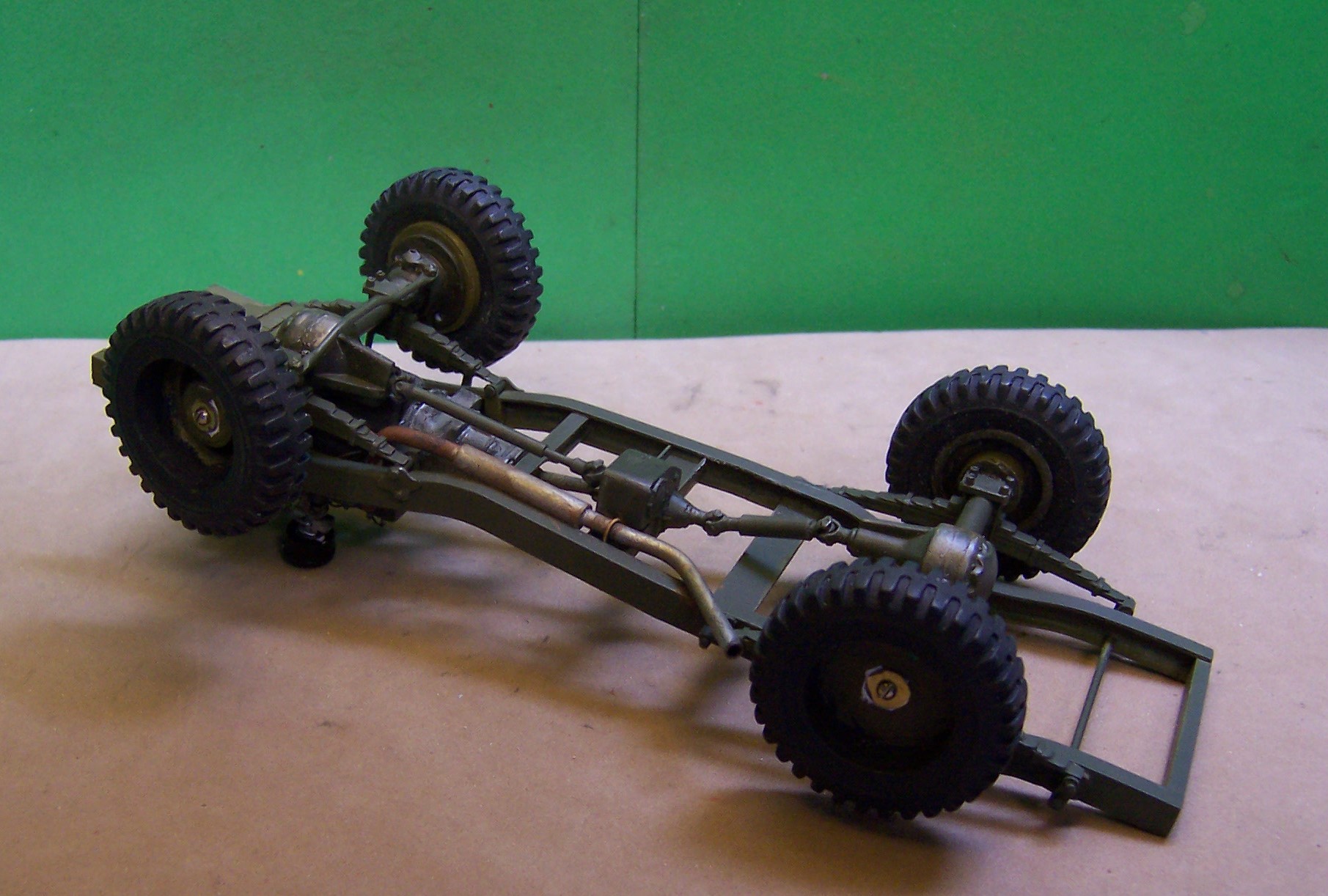
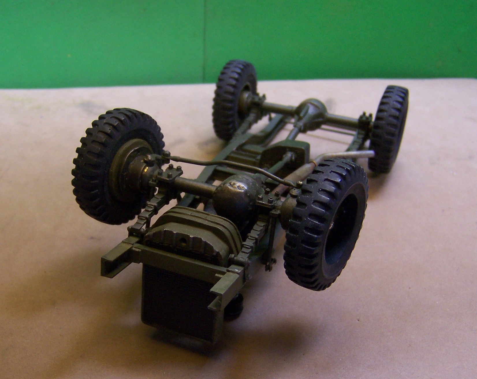
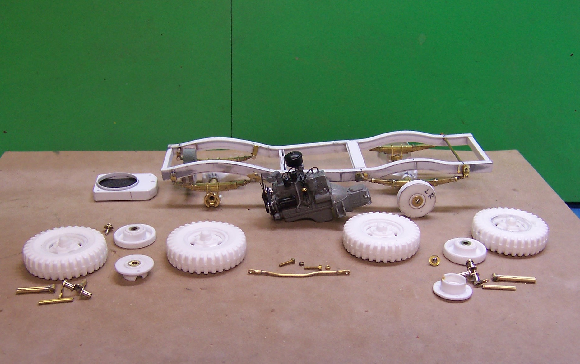
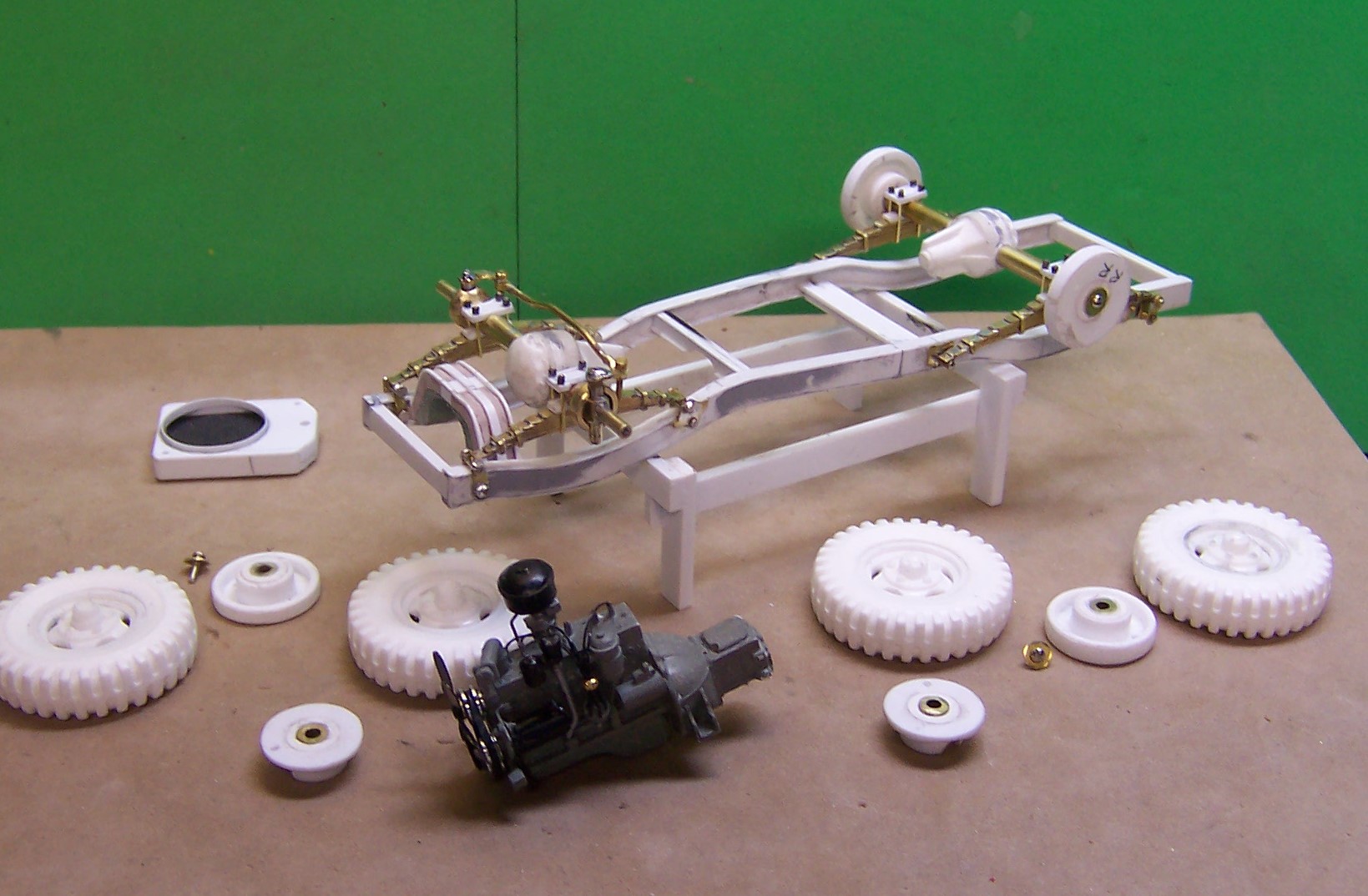
The gnomes have been busy in the shops the last few days with all of the rain we have had. Lots of detail stuff to get out of the way on the chassis. Plenty of brass works to get done and soldered up. Here's were we are as of today. A look at the various parts that have been made up for the frame and running gear. An upside down look at the axles, hubs and tie rod in place. It's up on all 4's now. Short and stubby but with a 98"wheel base and 9.00x 16 tires that's the look you get. And it is a 3/4 ton vehicle besides.
-
I pried the tires off with a small screwdriver. The wheels as snapped onto the axles on the inside and I could not save them so I had to cut the axle just behind the wheel. If I put the diecast back together it will have to be with a new axle made like what I'm doing now.
-
CCW it is. That is why I had to switch the fan around and put the longer cutting edge outside.
-
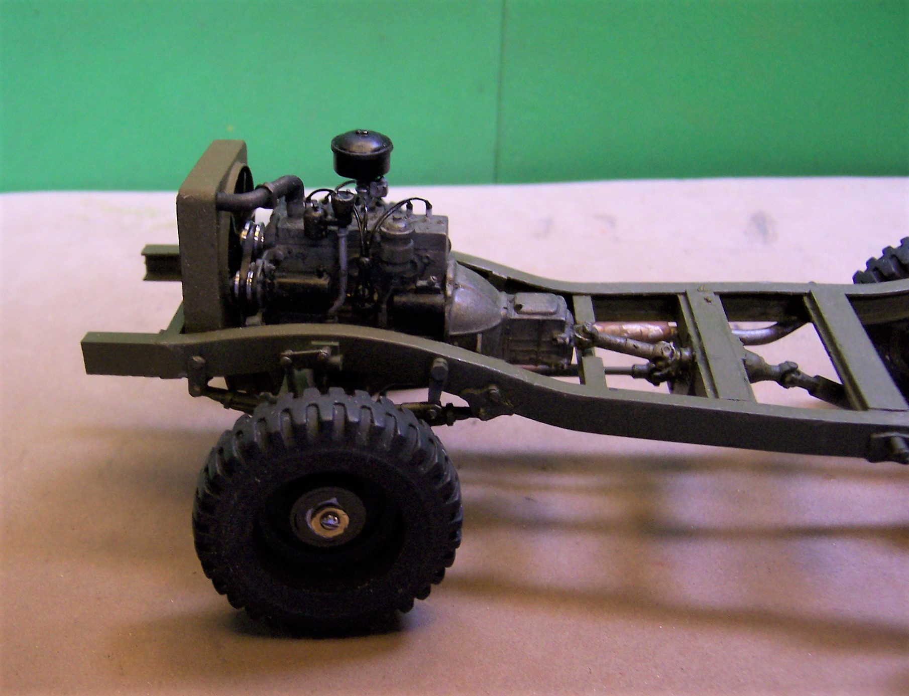
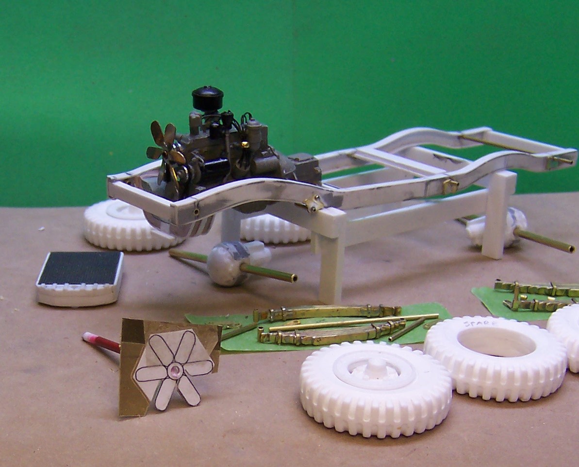
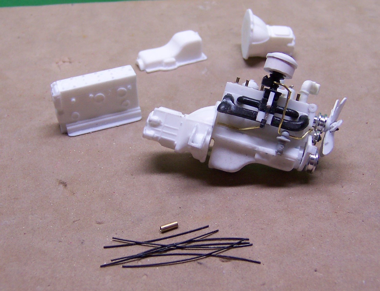
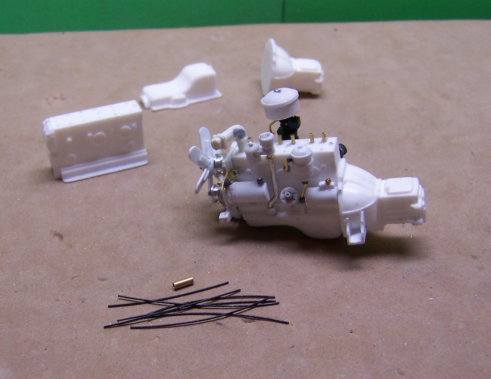
Bit the bullet and made a change in the fan. I was not entirely happy with the plastic fan even though it looked ok. The blades were just too flimsy and kept breaking off. So after being encouraged by another builder, I made a fan line drawing and then cut a new one out of brass. A twist of the finished blades with some small pliers, some finish filing of the edges and we are back in business. The first one I made got installed on the shaft backward so I had to unsolder it and turn it around. The photos that follow show the fan and how it was made. The fan on the engine in the background is backwards. It is now reversed with the blades going the right way. In this photo the drawing of the fan is taped to a piece of brass sheet. Cuts are made with a cutting disc in the Dremel. The first cut goes all the way to the circle in the middle. On the adjoining blade, the cut is made only as far as the first cut above it. That leaves a small amount of area on each blade than can be twisted a little as a real fan blade would be to draw air through the radiator. Here's a look at the fan that was finished. The leading edge of the blades should be the long side so it was removed from the shaft and turned around. Not in the photo but it is now correct. The unfinished fan will be saved for the second of the two WC-52's that are being made.
-
Lots of measurements and photos first, Jim, but yes. A future project for sure!
-
I painted the engine yesterday. The black acrylic has dried but it is so damp and humid the rest won't dry! Still sticky after nearly 24 hours. If it doesn't dry out soon I may have to strip it and start over.
-
In the fall of the year the leaves drop and older pine needles fall off leaving the litter on the ground. It forms a layer that is part leaves and needles and decaying matter from previous years. If there is not much snow during the following winter the litter (duff) stays loose and can be easily wind blown. When the duff is flattened down by snow pack it is less susceptible to rapid fire travel.
-
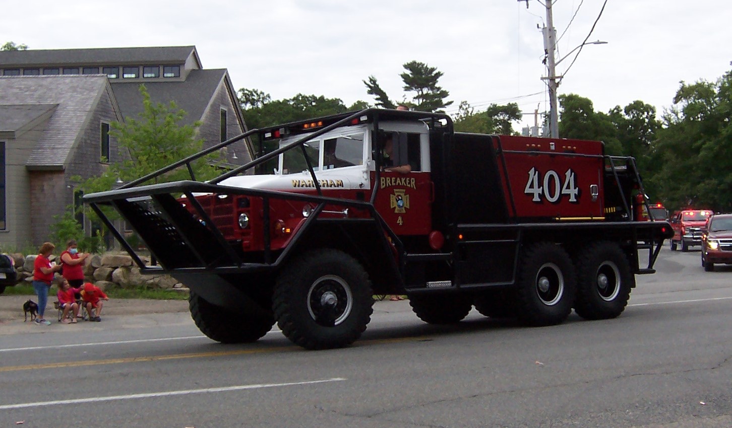
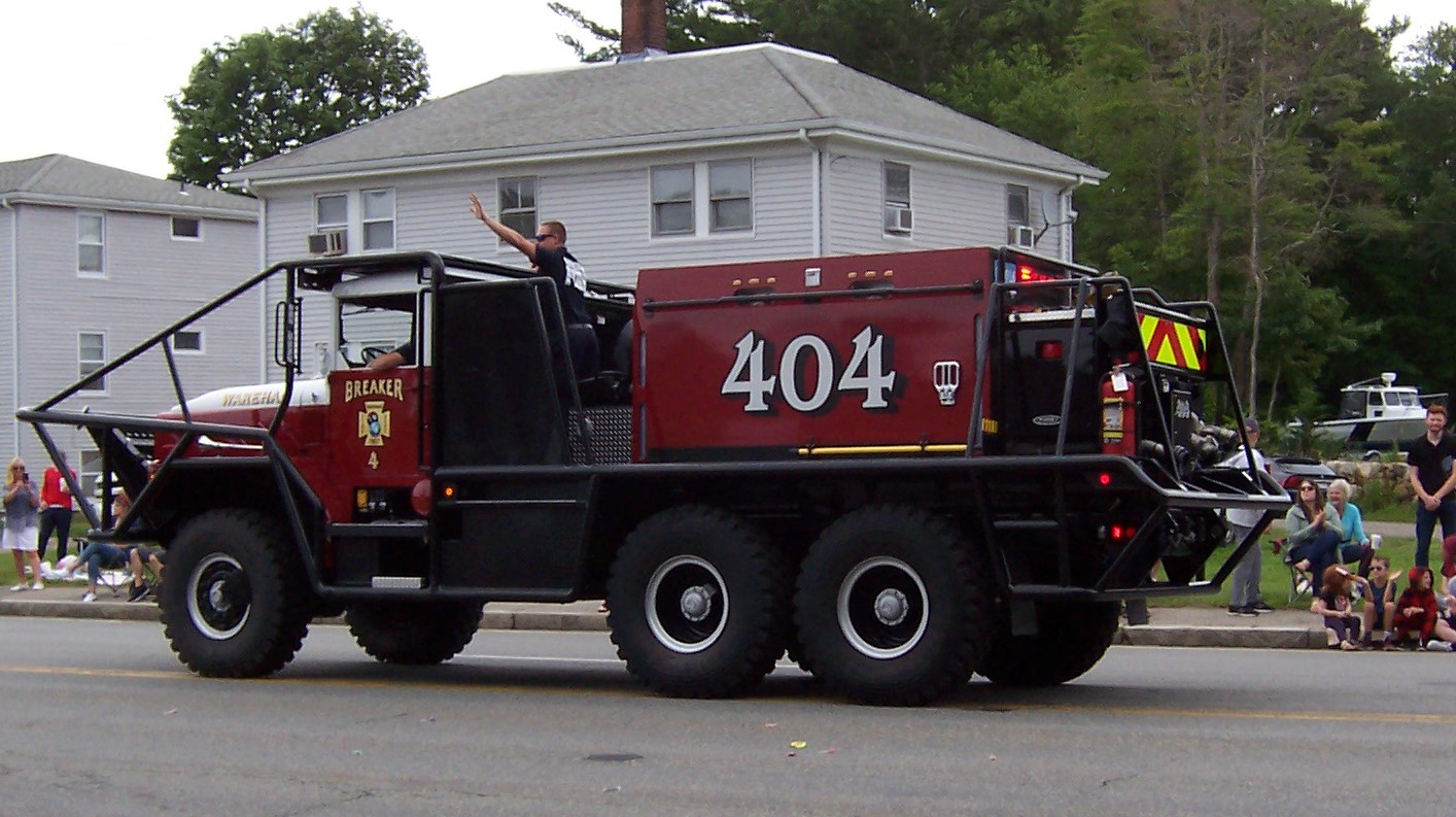
We haven't had many serious ones lately but they can pop up just about anytime, especially in the late spring before the leaves begin to come out. Even more so if the snow pack has not flattened the duff down. Those rigs are intended for going into the brush and woods, pinch the fire off at the flanks and go for the head. They work in tandem so when the first truck gets low on water the second in line takes the lead.
-
Have no idea what that is Ed!
-
My oldest son.?
-
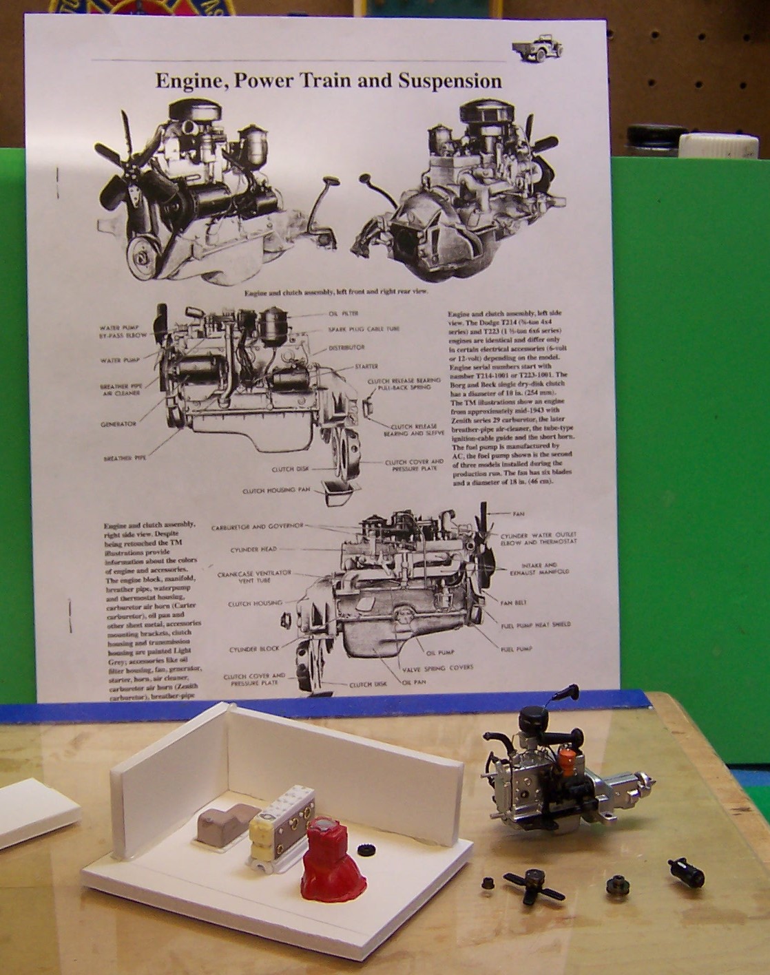
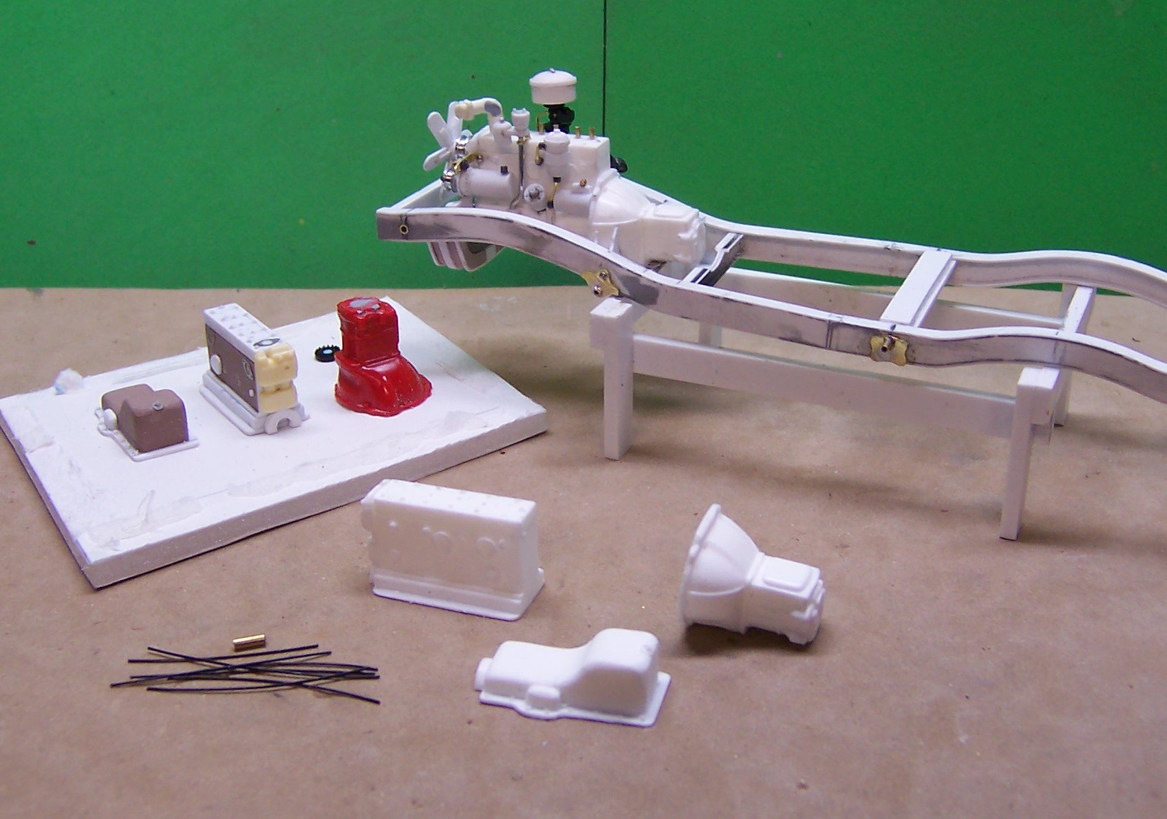
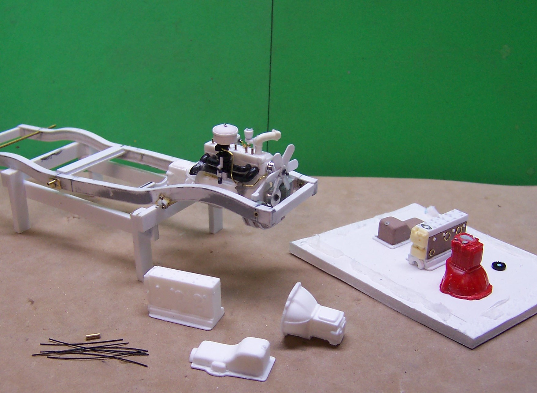
Got some more done in the engine. All basic building materials used in the construction. Ren Shape for the block and oil pan. Evergreen sheet, strip and tube stock for all of the detail parts. Aluminum rod turned into fan belt pulleys, brass wire, common pins, small brass imitation bolt heads, bead wire, fusion beads for hex nuts. The only kit pieces are the manifold that came from a cannibalized Opel Blitz kit and the bell housing which was from an old Ford V-8.
-
This is a new brush fire rig that our local FD recently had built. M939 5 ton chassis, 800 gallon poly tank, pump and roll capabilities, about 35,000 GVW. We call them "brushbreakers".
-
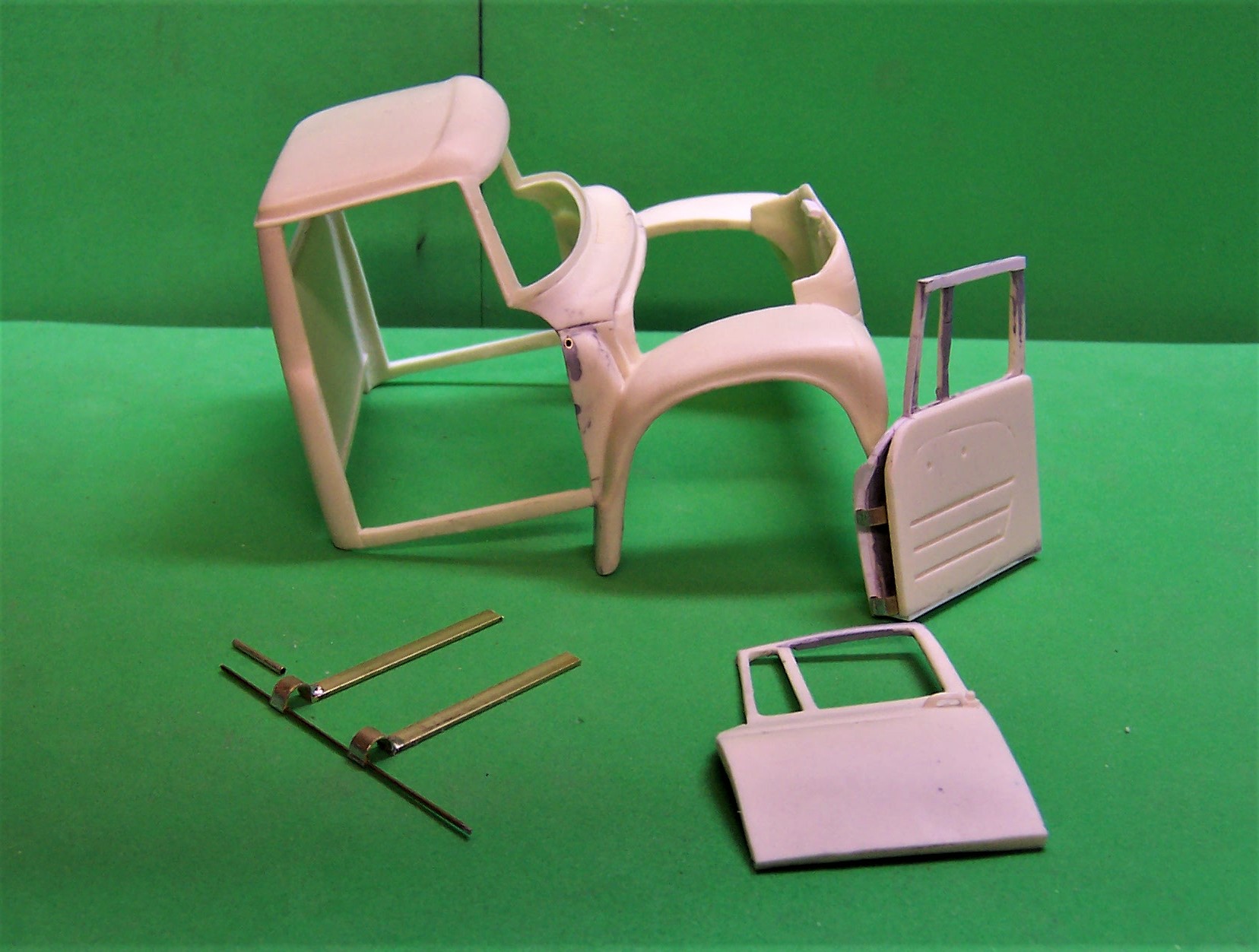
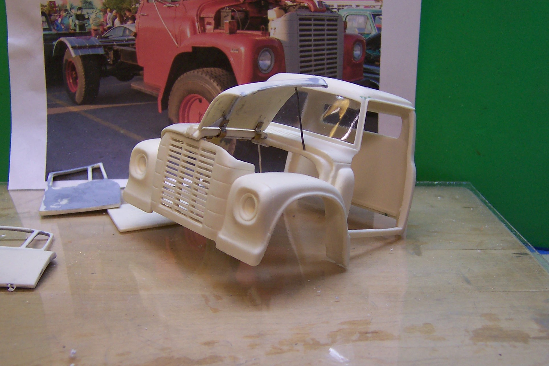
There are several ways of making outside hinges or exposed hinges but the two I like the best are using "H" hinges from Micro-Mark and making hinges using small brass tubing and steel wire. Here are some examples. In the photo above the small "H" hinges have been used. The come apart easily and instead of using the individual brass pins I substitute stainless steel wire long enough to hold both hinges at the same time. This allows for alignment on the doors and the door jam. CA works well to support them but drilling out the holes and adding small nails that come with the hinges keeps them secure. I grind off most of the nail heads afterwards so that the hinge does not bind. Both pieces are notched into the door and jam rather than just sit on the outside. Another example of an exposed hinge is this set made of brass strip stock, sections of brass tubing and again some very small brass tubing the stainless wire. In this case the hood of the International Loadstar is a butterfly type that opens on each side of a permanent center section. There needs to be clearance between the point of attachment of the hinge and the hood otherwise it would not open. Tubing sections were sliced in half and soldered to the brass strip stock. Then the half sections of tubing were soldered to a length of the small tubing at the ends. In the photo you can see the size of the small tubing between the hinges. These longer pieces are separate from the hinges themselves but the stainless wire runs through them all. The longer small tubing is secured to the hood with CA and is also set between two small pieces of plastic strip for extra grip. Here's a better look at the hinge parts after they were all soldered together. After soldering was done the extra small tubing was cut away leaving only the part soldered to the larger half round sections. The hood is open and everything is clear of binding. A similar piece is on the other side and opens the same way.
-
Bob: I use the resin from Micro-Mark. It's 1:1 mixing and hardens quickly. I don't have to worry about the temperature of the mixture. Just mix and pour.