Chariots of Fire
-
Posts
2,783 -
Joined
-
Last visited
Content Type
Profiles
Forums
Events
Gallery
Everything posted by Chariots of Fire
-
 I'm with ya on that. Good looking screen. Mine is brass but looks quite similar. I like using odd stuff and I'm always on the lookout for items that can be used to benefit scratch building. Craft shops and even sewing and fabric shops are great places to get materials. Have you seen the new package of tiny brass tubing by Trumpeter? Next time I'm at the LHS I'm picking some up. Four different sizes with pieces about 6" long and they telescope.
 -
The wire screen is from KS Special Shapes. I've had it a while and I'm not sure if it is still available. Jeff: The screen I used is not woven. It is flat like punched screening would be. Is that what you used on the snowblower?
-
1956 Great Dane Reefer
Chariots of Fire replied to KJ790's topic in WIP: Model Trucks: Big Rigs and Heavy Equipment
Archer rivet decals are really great. They stand out just enough after painting to look real. I've used them before on a truck that had a riveted body. I think the best ones to use are the O scale rivets. They make HO scale also but they are so small it doesn't make sense to try and use them. Great work! Outstanding attention to detail! -
Looking good, Greg! Warning light combo is nice. ?
-
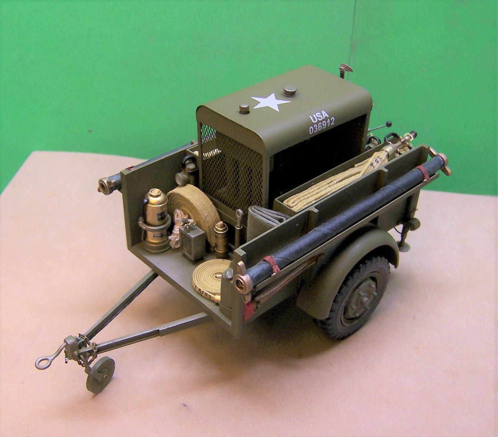
It carries a 500 gpm Hale pump powered by a Chrysler 6 cylinder engine. It also carried hose and tools for fire fighting. Some of these old trailer pumps are still around. They were put together by a host of different companies including Maxim, Howe, American LaFrance and others. They were towed by either the WC-52 or the WC-63. Here is one that I already have done for someone else. This one will stay with my collection.

-
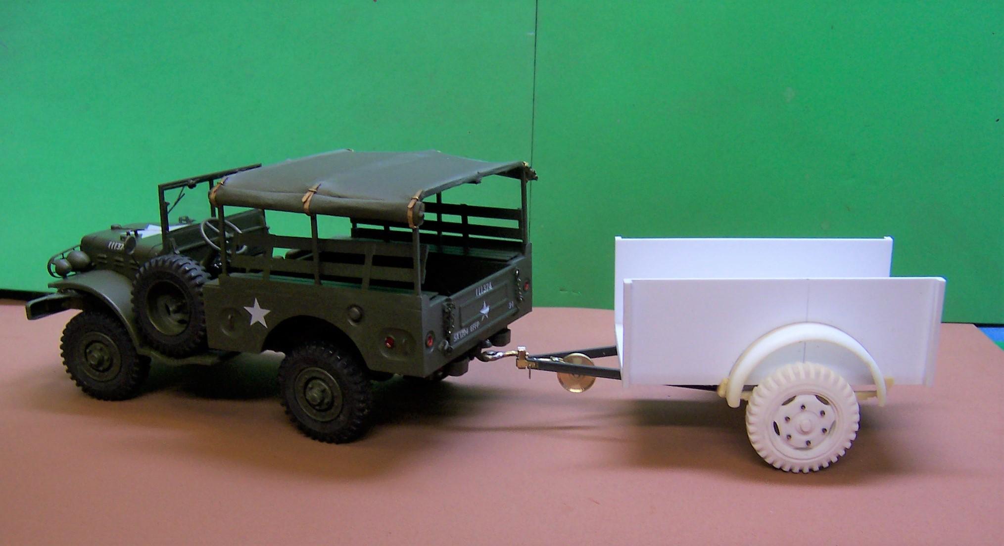
Hey, Paul! Sometimes I only work half fast!? But like Bob said I did cast some of the parts in the WC-52 build that will be the same for the WC-63. So there was a plan so to speak! The plan is also to build the trailer pump for the 63 to pull. Here it is attached to the 52 just for kicks.
-
XM523E2 & XM524E2
Chariots of Fire replied to nathanyel's topic in WIP: Model Trucks: Big Rigs and Heavy Equipment
WOW! that's all that can be said! Scratch building skills at its best! Thanks for posting. Looking forward to the finished product. -
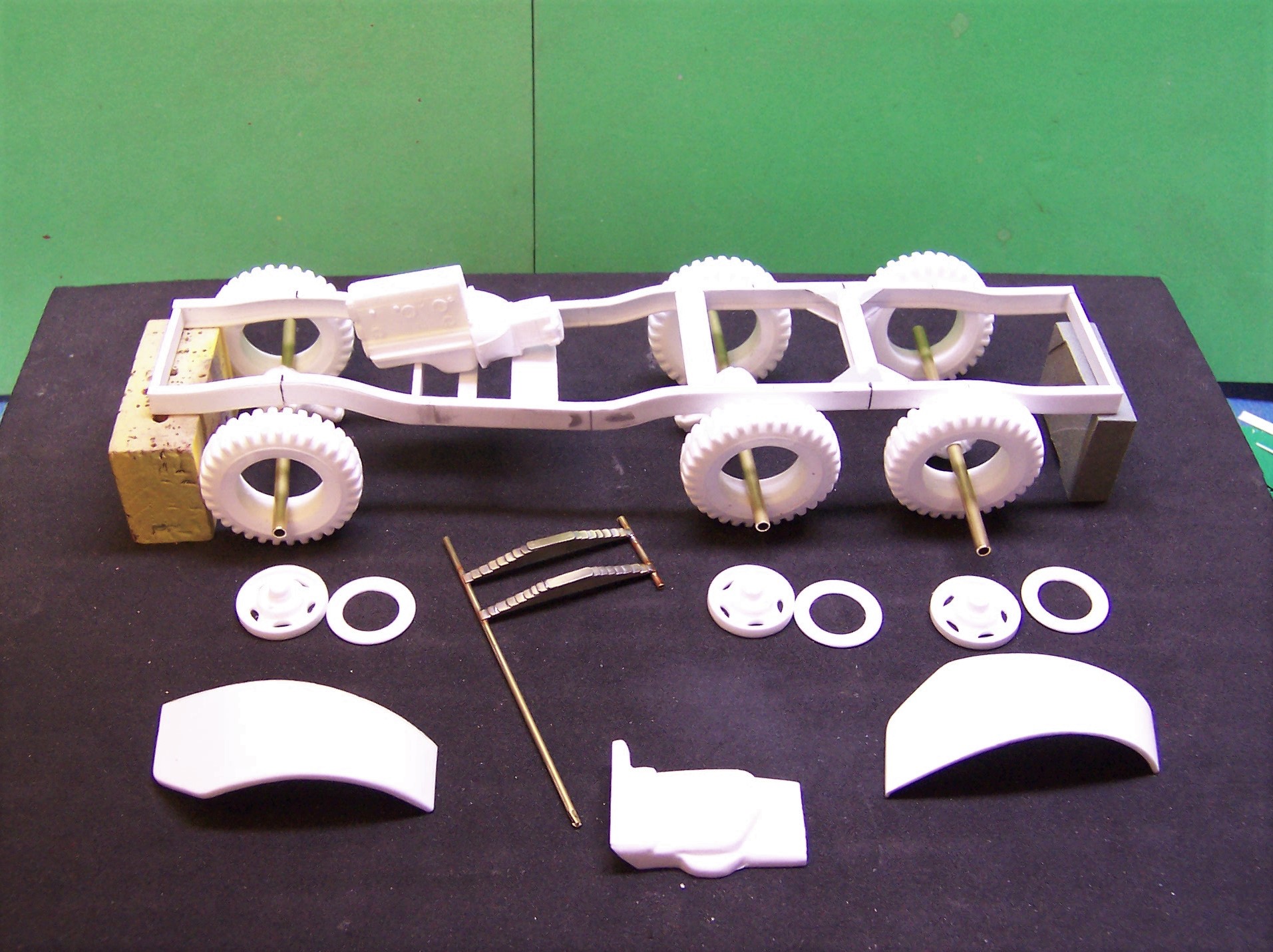
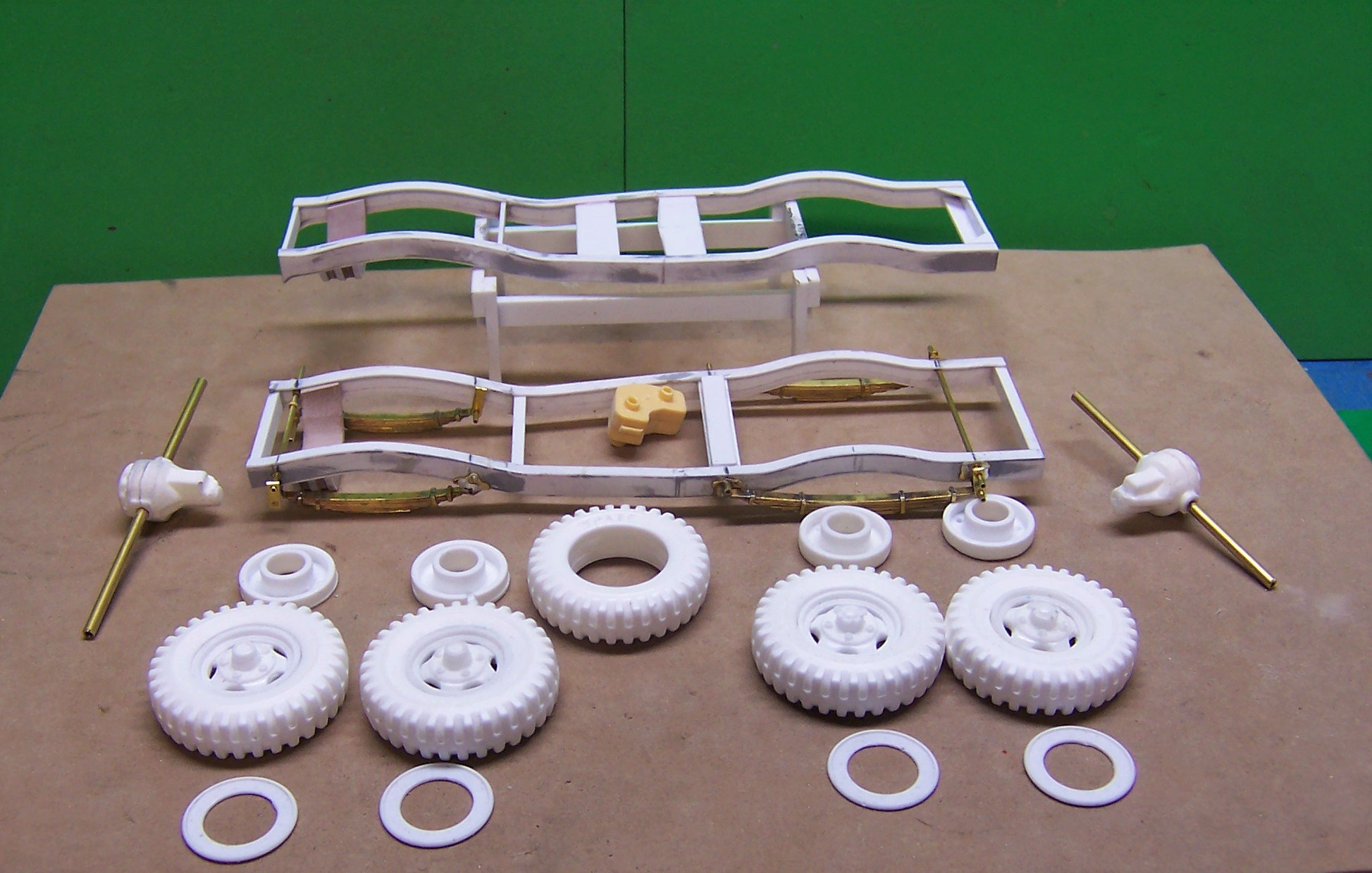
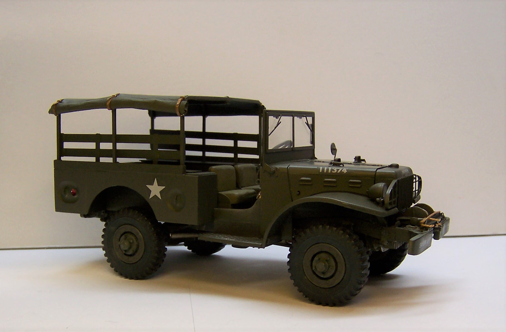
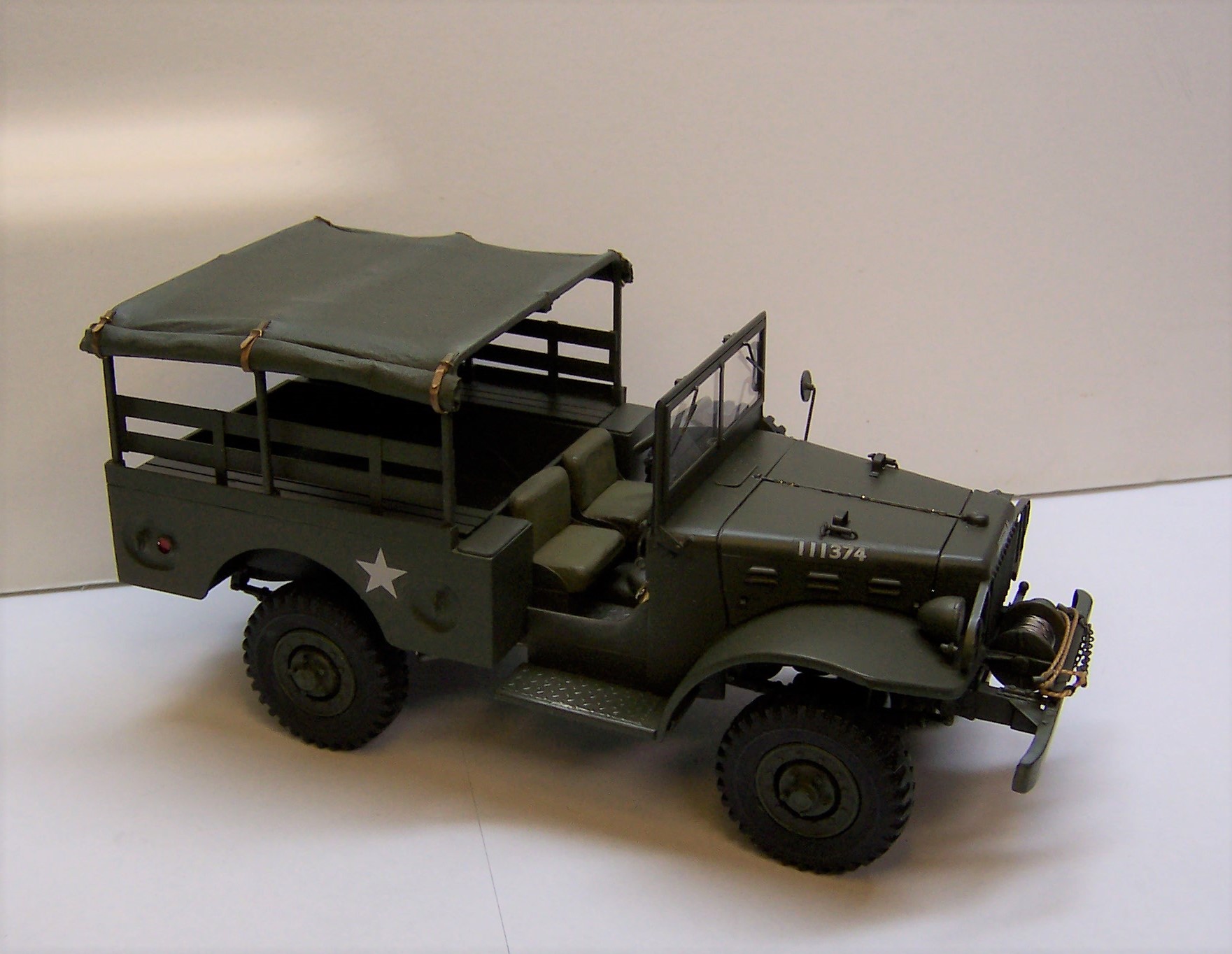
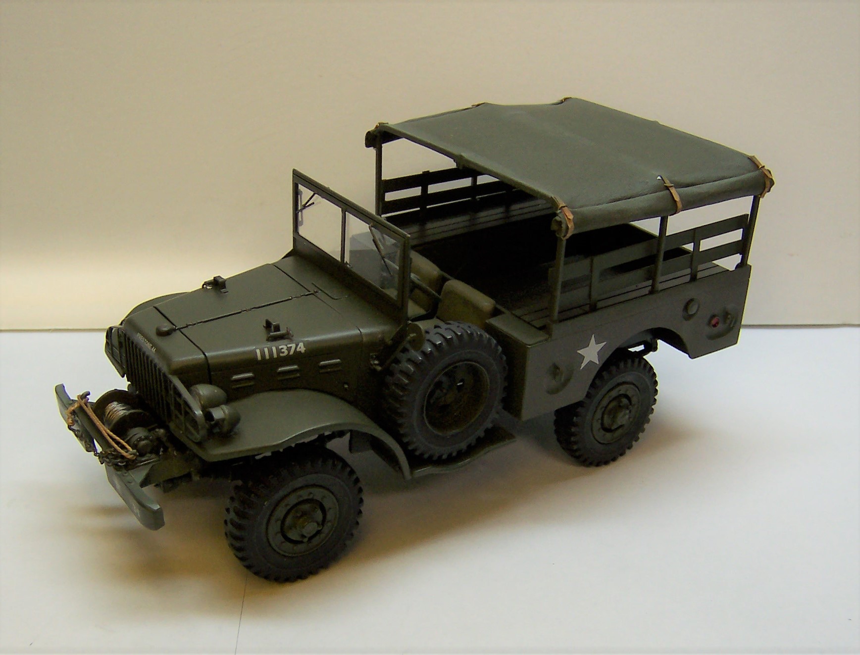
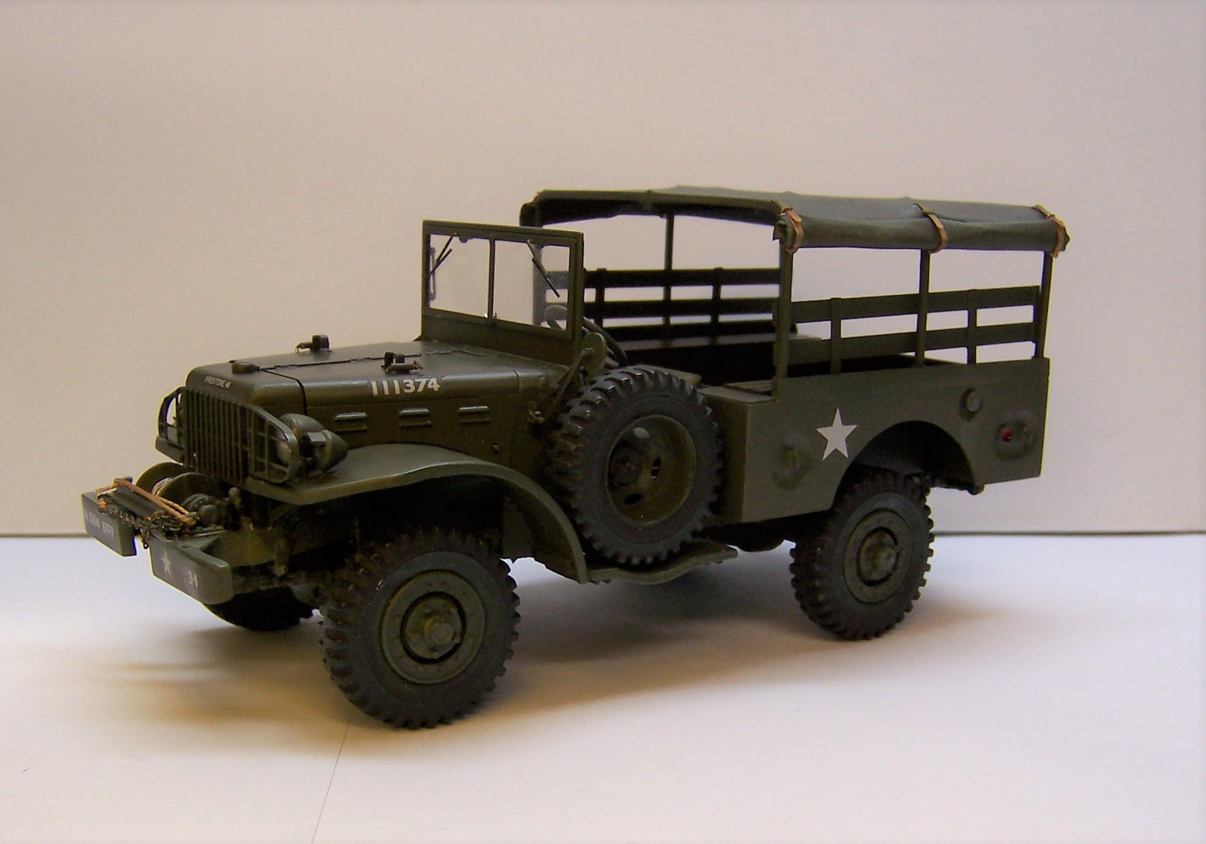
The WC-52 is now done. The next build is an upgrade in weight and size and is the WC-63. At 1.5 tons and 6x6 it is 4 feet longer than the 52. Here's where we are with the very beginning of the project. it is the same front sheet metal as the WC-52 and same engine. Different shape to the frame which was made of 0.040" sheet for the web and 0.020" strip stock for the flanges. Springs are made of 1/64 x 3/32 brass soldered together at the ends.
-
Mack B61
Chariots of Fire replied to The Brush's topic in Model Trucks: Big Rigs and Heavy Equipment
Where did the poseable front axle and tires come from? Great looking model. And a nice color combination. -
1970 Ford F100 (Moebius)
Chariots of Fire replied to Watertown's topic in Model Trucks: Pickups, Vans, SUVs, Light Commercial
What they said! It looks like it is supposed to look in those colors. Well done, sir!! -
Prostar
Chariots of Fire replied to Oldmopars's topic in WIP: Model Trucks: Big Rigs and Heavy Equipment
What they said! Nice neat work and a beautiful shade of blue. It takes some TLC to make one of these new rigs look nice and you did it! -
NO stars????????????
-
Navy Chevy Fueler query?
Chariots of Fire replied to Matt Simpson's topic in Model Building Questions and Answers
JP 4 is jet fuel so perhaps it is some type of fire protection unit. Never seen one like that before but that is my guess. -
resin casting and molds
Chariots of Fire replied to Paul Payne's topic in Model Building Questions and Answers
I don't claim to be an expert at this stuff. Most of it has come by trial and error but a good friend taught me some basic tricks about casting some years ago and I have just tried to expand on it as I have had need. There are other people who are much better at it than I am. My castings are for my own use so when I need something more than once, I try to figure a way to cast it. -
resin casting and molds
Chariots of Fire replied to Paul Payne's topic in Model Building Questions and Answers
Hi, Peter. On the tires I did for the Mashpee rig I did an initial pour only sufficient to rest the tire master on. In the second pour I made sure the bottom of the tire master was completely coated with RTV and set it on the first pour. Then I poured the rest of the RTV around the rest of the tire between the tire master and the edges of the mold box. I weighted the tire down just enough to keep the tire from floating in the RTV until it set. I brought this pour up to the edge of the tire tread and let it cure. You'll note also that the wood plugs are in this part of the mold. The last pour was done after I coated the second pour with mold release INCLUDING the small amount of RTV on the inside of the tire master. This last pour filled in the balance of the center of the tire and covered the exposed upper sidewall of the tire master. That is what you see in the second part of the mold. This is how I controlled the placement of the separation line for the tire. It made it easy to clean up. Keeping the bubbles out of the resin was not that hard. The resin mixture that I use does not produce a lot of air bubbles unless you really stir it vigorously. You don't need to do that. Pouring the resin into the mold a little at a time and swishing it around with a wood stick helps get the resin into the small deep parts of the tire. Once in a while I do get a bubble but not often. Many times they can be hidden or filled with a bit of putty. If not I just pour another one. On the military tire for the WC-52 that is shown in the WIP section for small trucks, they were easy to do using the center of the tread as the parting line. A little flash there was easy to sand off leaving it nice and smooth like it should be. The mold was a bit different in that I had half a tire in each piece. On that one it was necessary to let the resin begin to gell some before putting the two mold halves together so that bubbles would not get trapped. Not always successful doing that but again if it was too bad I just did another pour being a bit more careful. Below are the tires made for the WC-52. The mold separation line was right down the centerline of the tire.
-
1978 Ford F-150
Chariots of Fire replied to asfastasu's topic in Model Trucks: Pickups, Vans, SUVs, Light Commercial
Nice clean build, Aaron! Beautiful paint job. -
No. 1/25 scratch build.
-
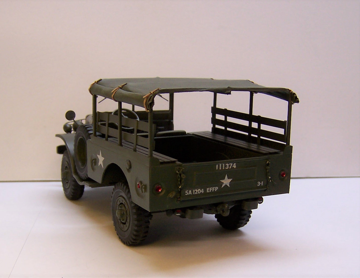
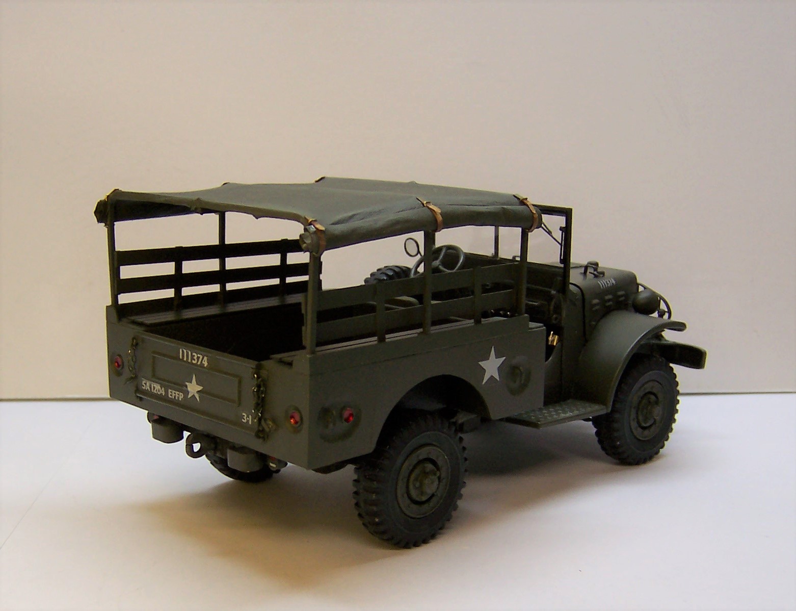
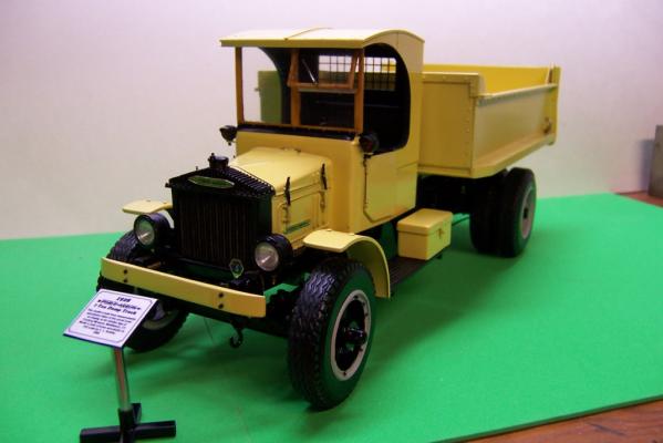
The work is done. Now to get it transported to its place of honor in the home of a WW II vet who served with a fire fighting platoon from 1943 to 1945. These rigs were the towing vehicle for the Class 1000 fire pump trailers that the Corps of Engineers used during the war.
-
Take some brass tubing, put in a vice and squeeze. It'll come out pretty close to what you want. Aluminum tubing would also work and you would not have to paint it.?
-
resin casting and molds
Chariots of Fire replied to Paul Payne's topic in Model Building Questions and Answers
Hi, Guys. Room temperature only affects it if the containers of resin are cool to begin with. The curing process produces a certain amount of heat so if the resin is cold to begin with it may take longer to cure. I store mine at room temperature and even if in the winter it gets into the 50's it doesn't affect it much. It's been quite humid this summer and I have done a fair amount of casting. I have not had any issues. Proper mixing is the greatest concern. The petroleum jelly you can find in any store like CVS, Target, etc. The release agent does not come with the casting resin or the RTV. You have to buy that separate. Although M-M does sell a starter kit that may contain the release agent. I'd have to go back and look. -
resin casting and molds
Chariots of Fire replied to Paul Payne's topic in Model Building Questions and Answers
Release agent can be petroleum jelly or the commercial release agent in a spray can like M-M sells. I've used both to equal success. I apply the jelly with a q-tip. You could use the slow setting resin with the same outcome. I like the quicker curing resin because I get impatient waiting for the M-M 600 to cure! It takes more time. In each case mixing proportions need to be accurate or you will get poor castings that will not set up fully. They remain soft and absolutely useless. -
resin casting and molds
Chariots of Fire replied to Paul Payne's topic in Model Building Questions and Answers
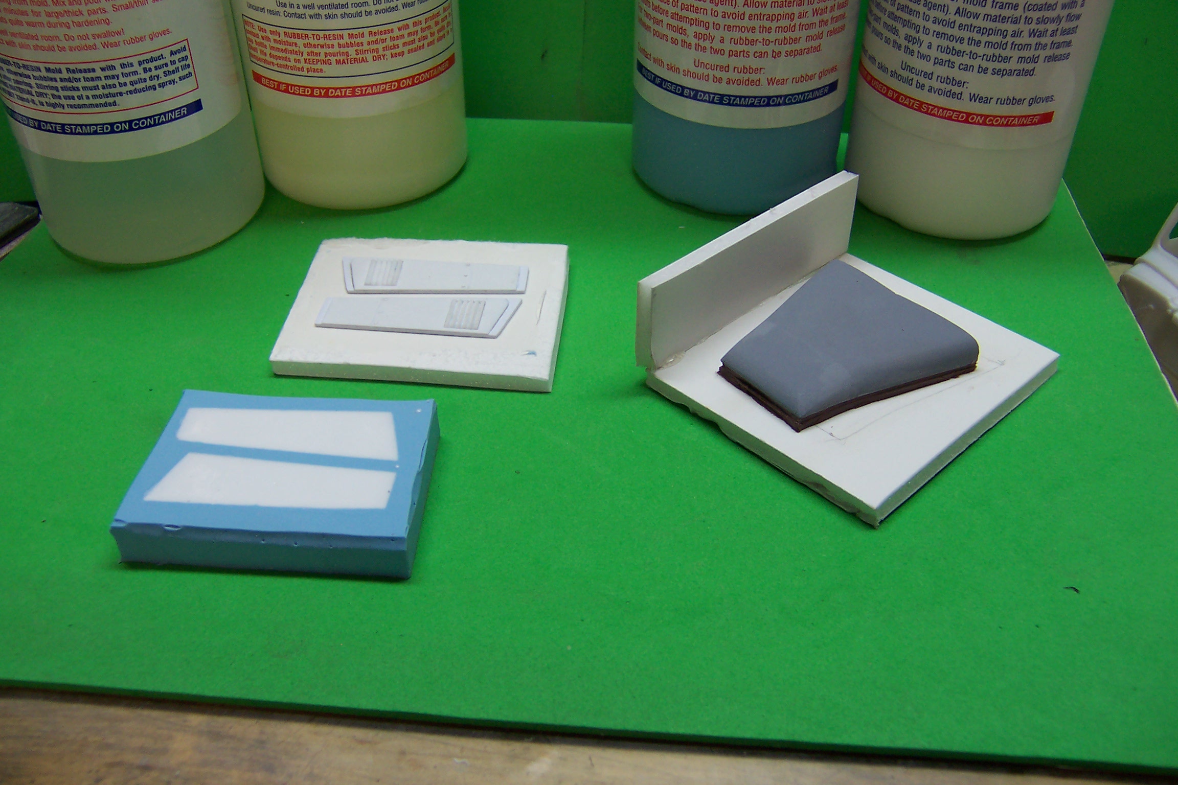
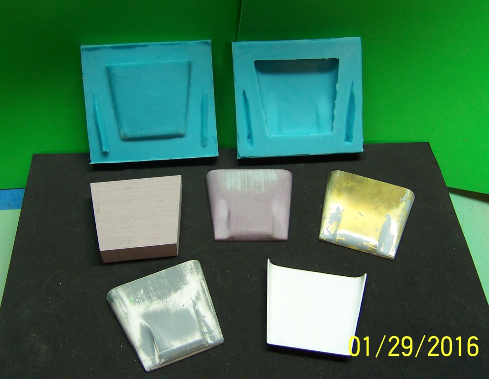
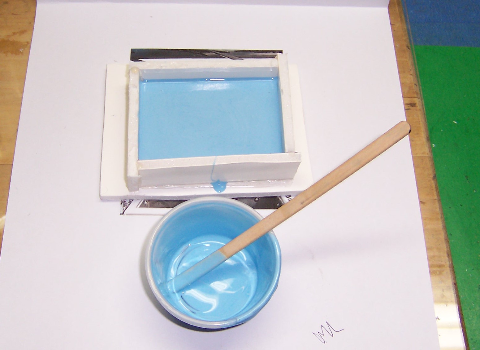
Making some parts require a two part mold. The mold is necessary whenever the parts to be made need complete casting and do not have a flat surface like the parts cast above. A tire is a good example. It needs to be fully represented, completely all around and on both sidewalls. The most important part of casting parts that need two part molds is to establish where the parting lines will be. For a tire that is in one of two places; either the line where the sidewall and tread meet or the center of the tire tread. In the latter case this works well with mud/snow tires or non directional tread designs like military tires. In the image above all of the tires you see were made using this two part mold. The first step in this process is to make a mold box as described above. Once done a small amount of RTV mold rubber is mixed and poured into the bottom of the box and is allowed to cure. Then a second batch of RTV is prepared and a very small amount is poured in on top of the RTV that is already cured. The tire master is then coated with mold release and is placed in this second pour of RTV and swished around gently to make sure that the entire bottom surface is covered with RTV. Note that in the mold above that is in front there is a center section that is much lower than the rest of the mold. This is the level at which the second pour is made. It is allowed to cure. At the same time some alignment plugs are put into the RTV and allowed to cure in place. It does not matter where they are and the more they are randomly placed the better because it will help later on in putting the two mold halfs together. After the second pour of RTV is cured, coat the entire inside of the mold box, the cured RTV surface and the exposed tire master with mold release. Allow to set up as per individual instructions. When that is done, mix up a third cup of RTV and pour directly into the mold box covering the tire master completely, stirring as you to to eliminate voids and air bubbles. Do it slowly and watch to make sure the RTV covers everything. A note about mold release. IF you forget to use the mold release and you pour the last RTV you will have successfully encapsulated your master in a mold that will not separate. Not good!? If you look at the two mold halfs above you will note that the near one has a notch cut out of the side. This was done after the second RTV pour had cured. This notch was also coated with mold release. When the top part of the mold was cast the RTV fills this cutout as well and adds to the alignment of the mold pieces. In the photo you will note that the plugs have a certain amount of cured resin on them. This needs to be cleaned off as much as possible so that the mold halfs match perfectly. Also the top half of the mold has a center protruding part that actually plunges into the resin and helps to squish out the extra resin in the mold. When pouring the casting resin, the mold needs to be filled completely, again checking for trapped air bubbles. Make sure that they are gone! In this case the front mold half is overfilled so that when the top half is placed over it the extra resin is pushed away. In the photo I have shown the mold on a glass plate which is my building surface. I always place two layers of paper towels on the glass plate and set the mold on them before pouring. When the extra resin drips out it just goes into the paper towels and does not leave a mess. Below is a second type of two part mold; this time for the hood of a WWII vintage Chevy 1.5 ton truck. Those are the hood sides to the left in the photo. They were made using a one piece mold like described above. But the hood mold is different. I started out with a foam box as before and placed the hood master on a layer of clay. Why? Because I made the master as thin as I could using Ren Shape and it is hollowed out; not solid. The hood is then mounted on the clay and the clay is cut away from around the edges using an Xacto knife. It needs to completely seal off the underside of the hood. When this is done the mold can be completed and the RTV poured in just like a one piece mold. After the mold has cured the RTV and the master and the clay need to be removed from the mold box. DO NOT remove the master. The next step is how the underside of the hood get cast into the mold. In the photo above the first half of the RTV mold has been placed on a piece of foam and new sides have been built up around it with more foam pieces. This is done with the initial RTV mold containing the master turned upside down. The clay is now completely removed from the initial mold leaving the underside of the hood exposed and to top of the hood sealed in the existing mold. Clean the clay out completely including any small pieces of clay residue. Spray or coat the entire underside of the hood, the exposed faces of the RTV mold with mold release being sure to get the inside faces of the mold as well. Then mix up a second batch of RTV and pour it in the mold to set. Remember to put a couple of variable notches in the sides of the existing RTV mold before you pour. This will be how you align the two mold halfs for casting the hood later. The hood above is one that I made for a 1957 Diamond T 5 ton military rig. I scratch built the master from Ren Shape and then made the two part mold as described above. Note that the right half of the mold is the first piece. It has the shape of the top of the hood and two notches cut out to align the left half of the mold. The Ren Shape block in at the left, the shaped hood is in the middle and an attempt at a brass hood is on the right. It was not used. Casting resin is poured into the right half filling it up to the top. The left half is placed on top and the excess resin is pushed out by the top mold contours of the hood. Left to cure and taken out of the mold you get the hood casting like the one in the foreground left and a look at the bottom showing that it is completely hollowed out. The exact same preparation of the mold for this hood was done as described for the Chevy hood above. I hope this little tutorial give you some ideas and helps expand your model building experience. Casting your own parts makes modeling more fun!!
-
resin casting and molds
Chariots of Fire replied to Paul Payne's topic in Model Building Questions and Answers
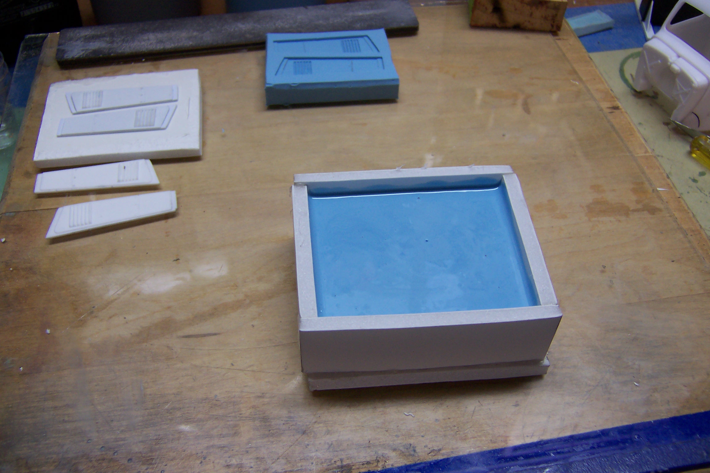
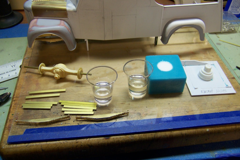
In the photo below I am making wheel hubs like the one to the right. They came from an Ertl ALF kit but they are good for any truck model that needs them. Again, the mold was set up as described above and in the middle is the finished mold with the cured resin in it. Along side are two small cups that I use to mix the resin. Most castings I do are quite small so it is not necessary to mix up large quantities. What you see are two communion cups, ordinarily used for a much more serious and personal purpose. I found a box of 500 at a supply house for about $12 plus shipping. The two part resin (50/50 mixture) needs to be measured in equal parts. One cup is marked about half way up with a felt pen. Then that cup is placed inside the second one. If you do that there is a space between the bottom of the inner cup and the bottom of the outer cup. Just mark the outer cup with the felt pen the same distance down from the mark on the inner cup as the space between the two bottoms. You will have equally marked cups for pouring the A and B parts of the resin. If you look closely you can see the marks on the sides of each cup with the resin components in each one. From here you need to pour the complete contents of one cup into the other and then stir until the two parts are completely mixed. I use two part resin from M-M 300 series. It is a fast setting resin so there is not much working time. At first the mixed resin will begin to thicken and then cloud up. If that happens before you pour, it's too late. It will not fill the mold completely. When set, the resin turns white like what is in the blue mold above. \ Now on to the two part mold.
-
resin casting and molds
Chariots of Fire replied to Paul Payne's topic in Model Building Questions and Answers
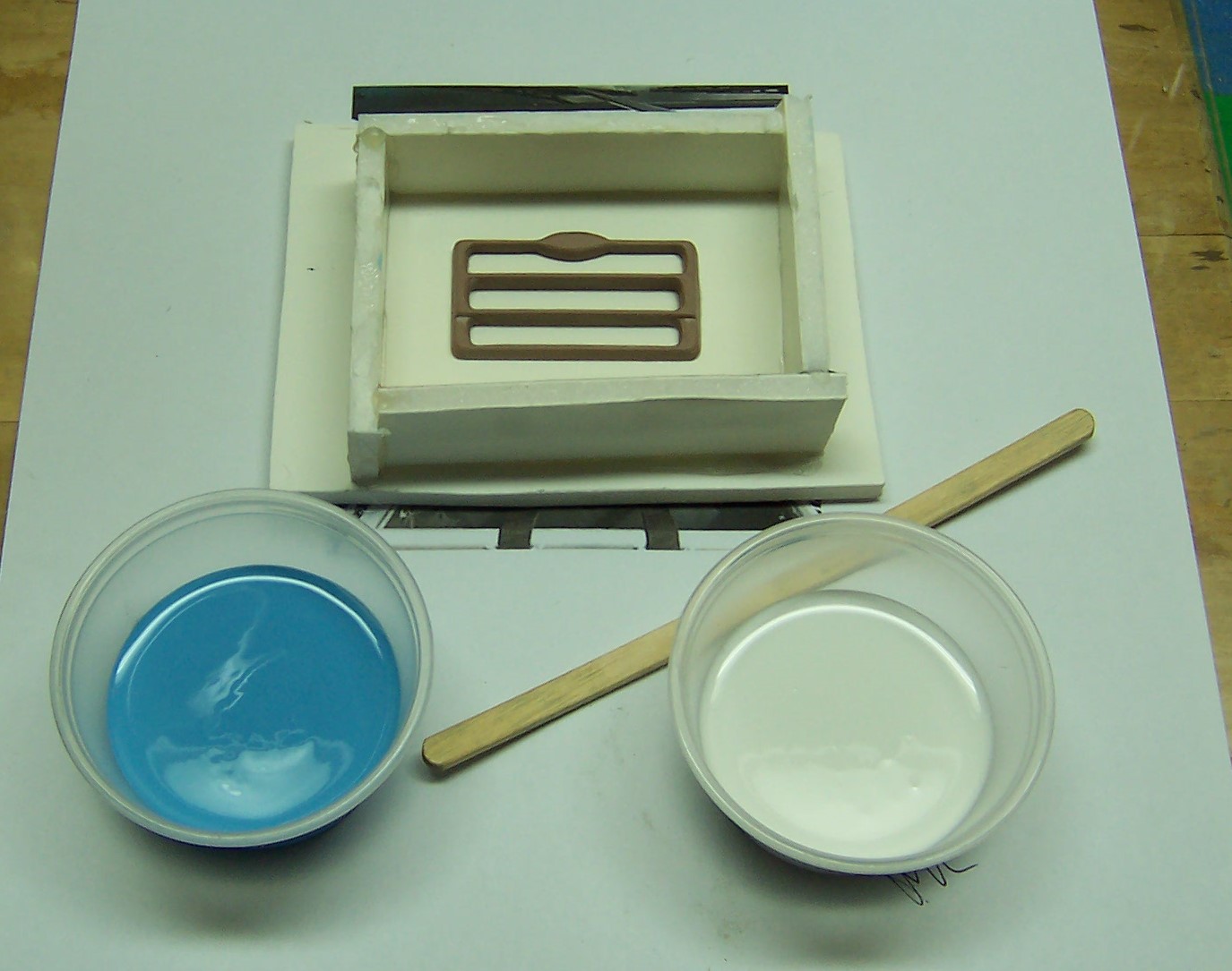
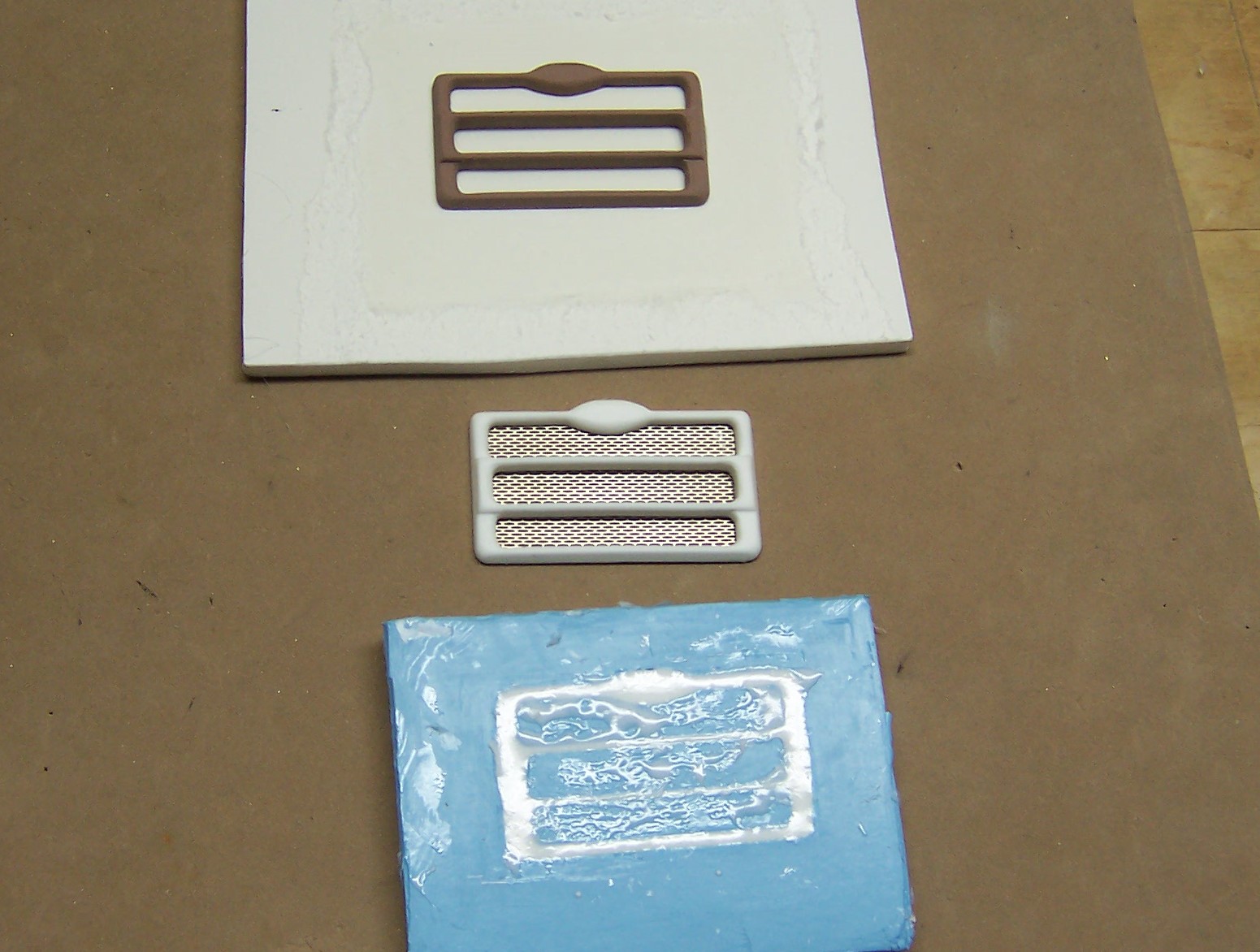
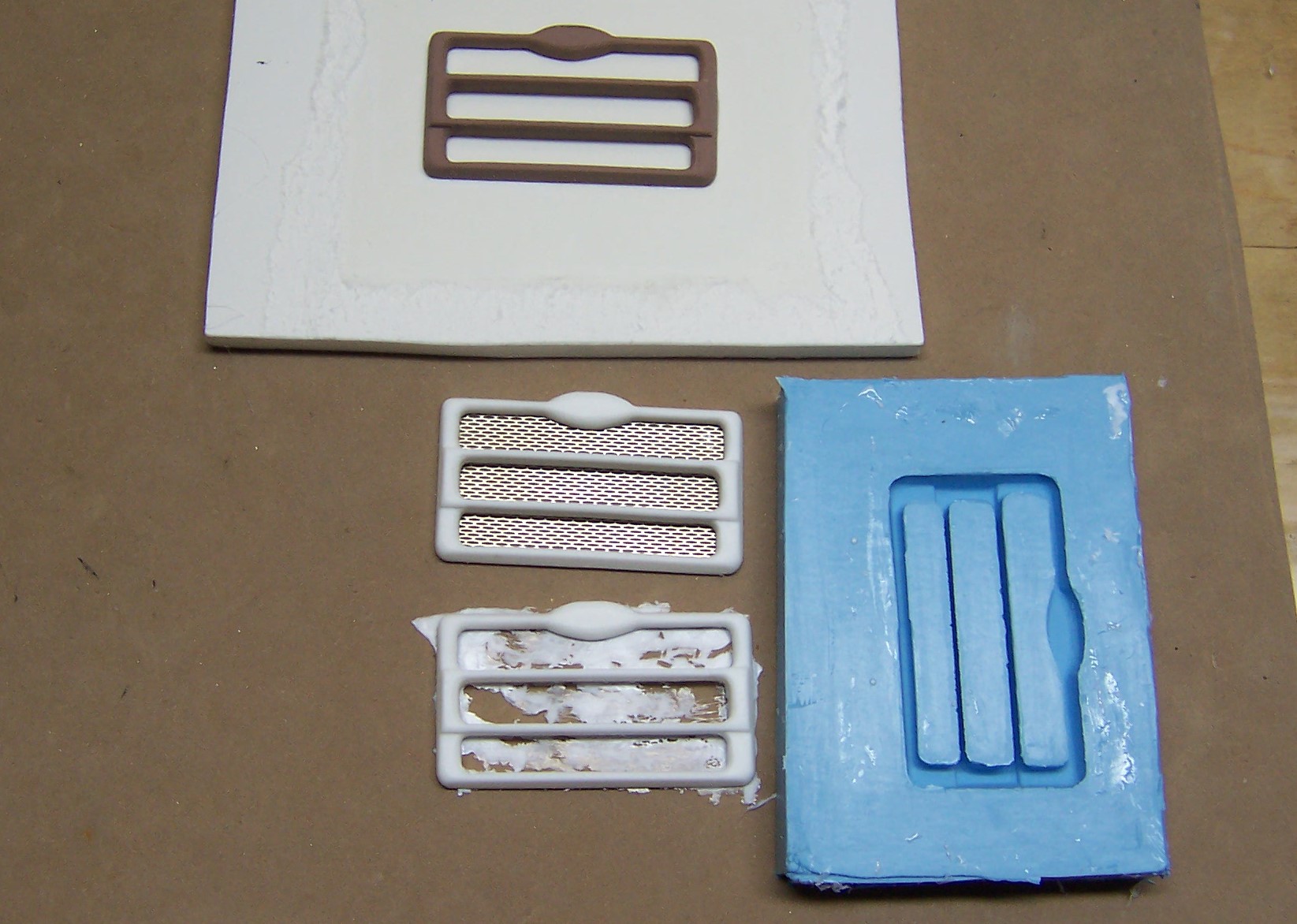
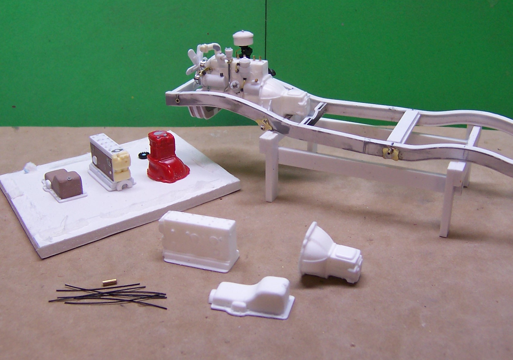
I'll start by showing a simple mold for a truck grill I needed for a piece of fire apparatus. I built a box out of foam board using a piece for the bottom as well. I use a hot glue gun to put the pieces together. In the photo the master for the grill has been made and is glued to the base. In the foreground are the two parts of the M-M RTV. Some people use a third cup and pour the contents of each cup you see into it. I just pour all of the blue part into the white part and mix it well. In the photo below the mixture has been poured into the mold and will be set aside to cure. It is a good idea to spray the mold and the master with mold release agent before pouring. This insures that the cured mold will separate from the master and the box without tearing. The RTV should cover the master completely. Use a probe and move the RTV around in good shape as you are pouring, making sure that there is no trapped air that will leave a void. This is especially true if the master has any amount of undercut. Once the mold has cured you can tell that by touch. If by touching the mold surface it leaves a finger print, the mold is not fully cured and it will be tacky. Let it cure for 3-4 hours. After it is cured break away the sides of the mold box to reveal the mold. Carefully pull the mold away from the bottom of the box and master. You will end up with a mold like shown below on the right. In addition two castings have been made of the grill already. The upper one has a piece of photoetch mesh behind it to show how it will look. Note in the photo above the bottom casting. That flash is just a skim coat. When pouring the resin for casting in a mold such as this the mold needs to be filled completely, obviously and without any bubbles or voids but you don't have to over fill the mold. If you get too much resin in the mold screed some of it away and you will be left with only the smallest amount of flash to remove from the cured resin. Here is another mold being made to produce an engine block, oil plan and bell housing. The masters are made of plastic, Renshape and a bell housing from the parts box. The exact same procedure outlined above was used to produce the resin copies shown in the photo below. The masters are on the foam block with copies of each piece shown next to it and an assembled block and bell housing using a second set of resin castings to build up the engine. Below is the grill casting in the mold. In this one there is just a bit too much resin that when cured will have to be sanded away to make it flat on the back surface. Next up I'll go over the kinds of containers I use for casting the resin and will show a pour for a two part mold.
-
What do the pros use to print decals?
Chariots of Fire replied to jchrisf's topic in Model Building Questions and Answers
HI, Peter. I did find the cartridges on eBay and they should be in tomorrow. Need now to check my inventory to be sure I have enough of the other colors for a while. Walter: Tell me more about the HP ghost white colors.