Chariots of Fire
-
Posts
2,782 -
Joined
-
Last visited
Content Type
Profiles
Forums
Events
Gallery
Everything posted by Chariots of Fire
-
Amen to what others have said. Good clean discussion, great modeling tips and lots of neat stuff to see. Thanks, MUCH!
-

Heil garbage truck, 1970s
Chariots of Fire replied to Repstock's topic in Model Trucks: Big Rigs and Heavy Equipment
That is quality craftsmanship! Well done!! -
Whew! That's an awful lot to take in. Like any other vocation or avocation, there are great examples of exceptional execution and there are examples of not so great execution. The difference is generally obvious. Claude, I like your approach! For me there never will be in this life true perfection so striving toward it is about all we can do. We share a common interest in creating something in miniature that is as much like the real thing as we can make it. And in some instances it involves creating something that in our own minds is what we fantasize over and would never become a reality. Doesn't really make much difference as long as we are enjoying what we are doing. How far each of us want to take the skills we develop as we progress in life is always up to us. And that goes for doing something as basic as model building. Do you enjoy doing it? Does it fill a void? Are you satisfied with the results? Can you live with the flaws you know are there but no-one else does? Want to see how many models you can build in a year? Go for it. I won't be envious. I'm lucky to get a couple done. If you want to get philosophical about it and believe there will ultimately be and end to this ball that is floating around in space, model building doesn't really amount to much. But God gave each of us a desire to build, to create. How we do it is up to each of us and in our own way and time. By the way, have fun doing it and share what you know with someone else. Isn't that what it is really all about??
-
How often do you have to clean up the looper? I use an old disecting needle much the same way you use the looper but I have to scrape off the excess CA every so often or it tends to build up.
-
How can I make these tires look better
Chariots of Fire replied to chris chabre's topic in Tips, Tricks, and Tutorials
I agree with deuces. Sidewalls are never really black unless you make them black with Armorall. The surface tread is darker because it gets scuffed on the road. But the sidewall is a grayish color. I found Tamiya acrylic weathered black to be a good paint for tires. -
I'd try and use the picture of the bike as a basis of measurement and compare it to the built up model. Proportion the spring measurements accordingly. Micro Mark sells a package of springs of all kinds that might give you a start on what you need.
-
Ford F-150 Raptor
Chariots of Fire replied to Dhgfx4's topic in Model Trucks: Pickups, Vans, SUVs, Light Commercial
Here's a thought for the third brake light. Cover it with bare metal foil and trim to leave just a tiny bit of the blue on the edge. Then where it should be red apply some Tamiya clear acrylic red to it. If there is a "white" portion, try a bit of thinned out white or leave the BMF as is. The build is very nicely done! Nice crisp paint job for sure! -
Working Around Red Plastic?
Chariots of Fire replied to JollySipper's topic in Model Building Questions and Answers
I don't think heat is the culprit. All kits that I have had that have this problem have been in my basement where temps are cool even in the heat of summer. Definitely an issue with the plastic itself. -
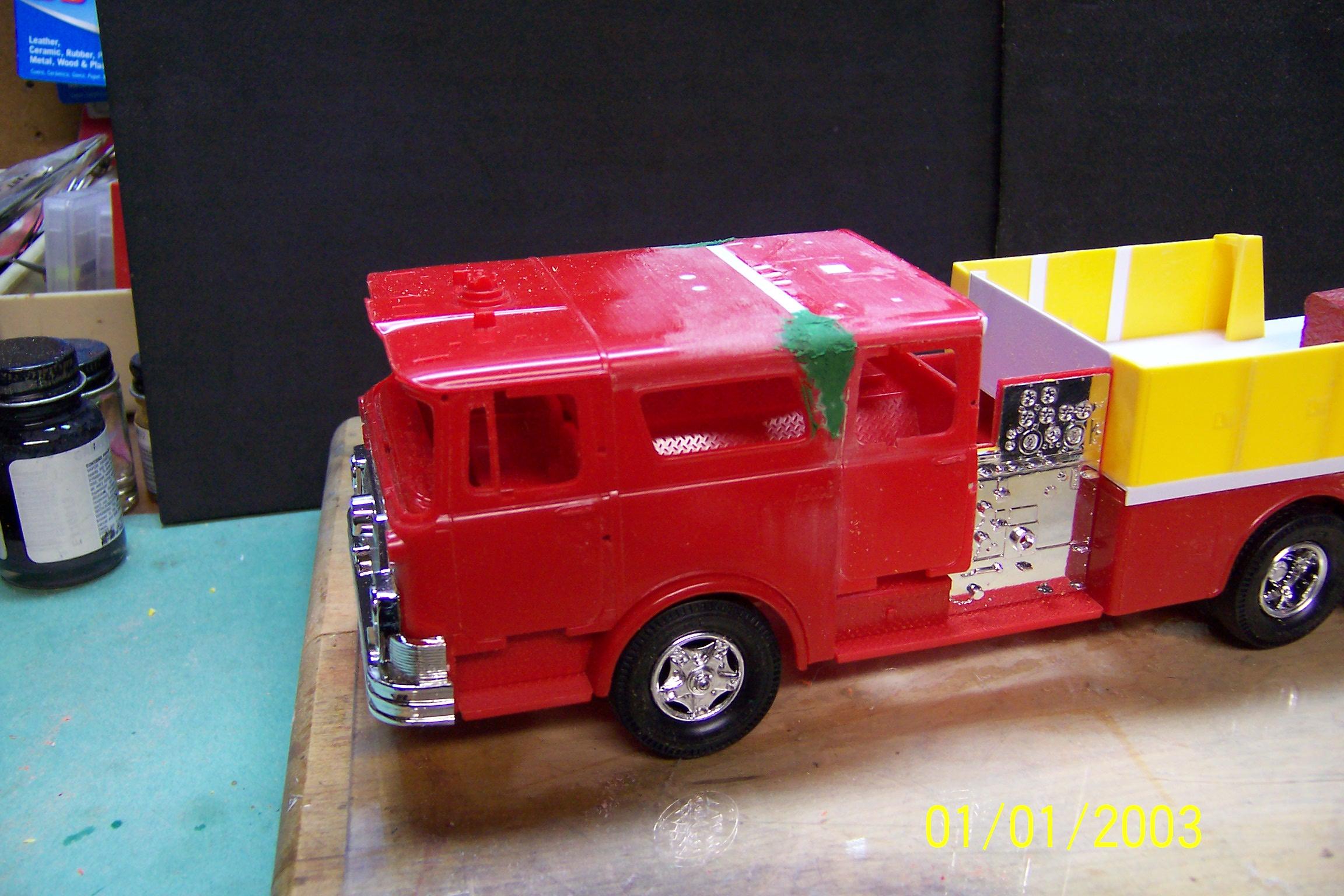
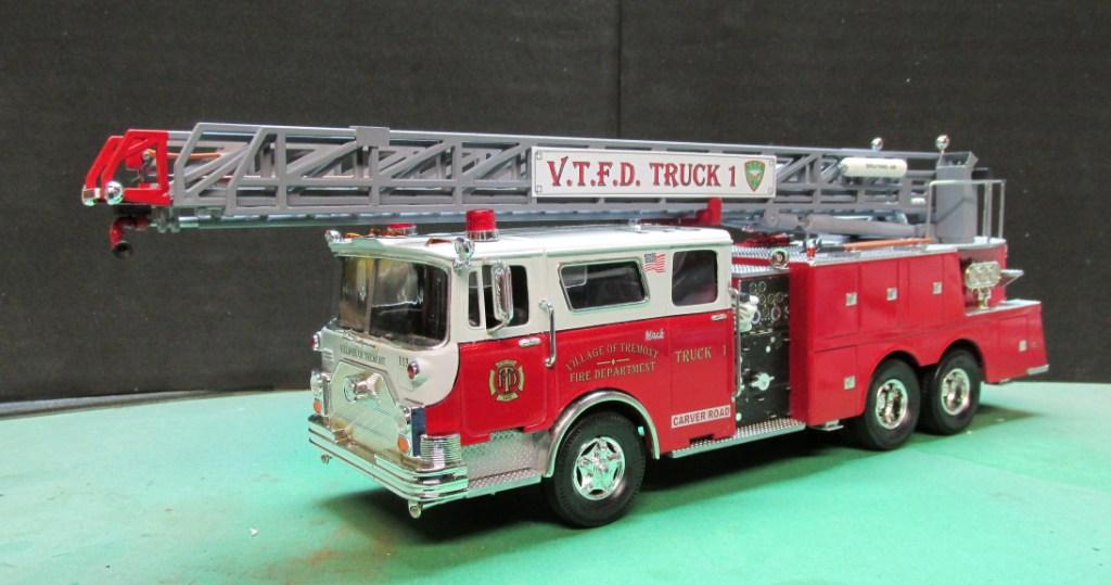
Working Around Red Plastic?
Chariots of Fire replied to JollySipper's topic in Model Building Questions and Answers
I've had mixed results. A while back I built this aerial ladder model using two Monogram snap kits. The kit plastic in each case was yellow the first try. I primed the cab with gray primer. One one of the cabs the yellow came through. On the other it did not. So I scrapped the yellow one and went to the red ones. But before cutting them apart and gluing I primed the inside of each cab to see what would happen. One nothing. On the other the red came through. I got another red cab and again painted the inside with primer. Nothing happened. So I proceeded to splice the two non-reacting cabs together as shown. Conclusion: Some plastic is reactive and some is not so it must be the type of plastic used in the molding process that causes the trouble and that all plastic used in the same type kits is not always the same. (Ignore the date on the photo. It was not set in the camera.) And below is the end result.
-
Truck Overload
Chariots of Fire replied to tiking's topic in Model Trucks: Pickups, Vans, SUVs, Light Commercial
Let's hope there are no tight turns along the way to where ever they are going! Could lose the whole thing!? -
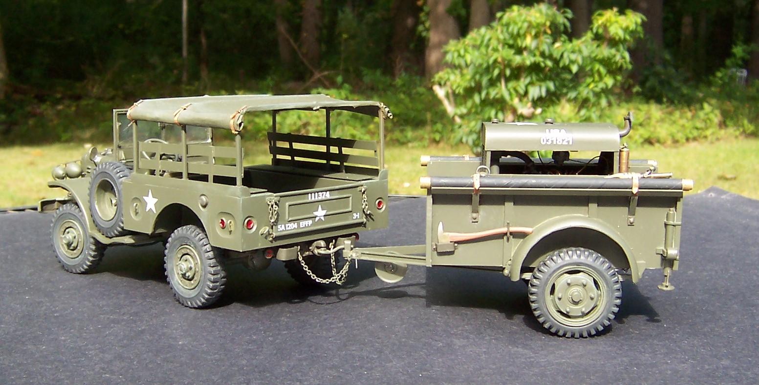
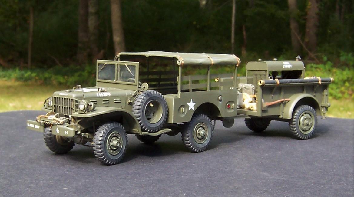
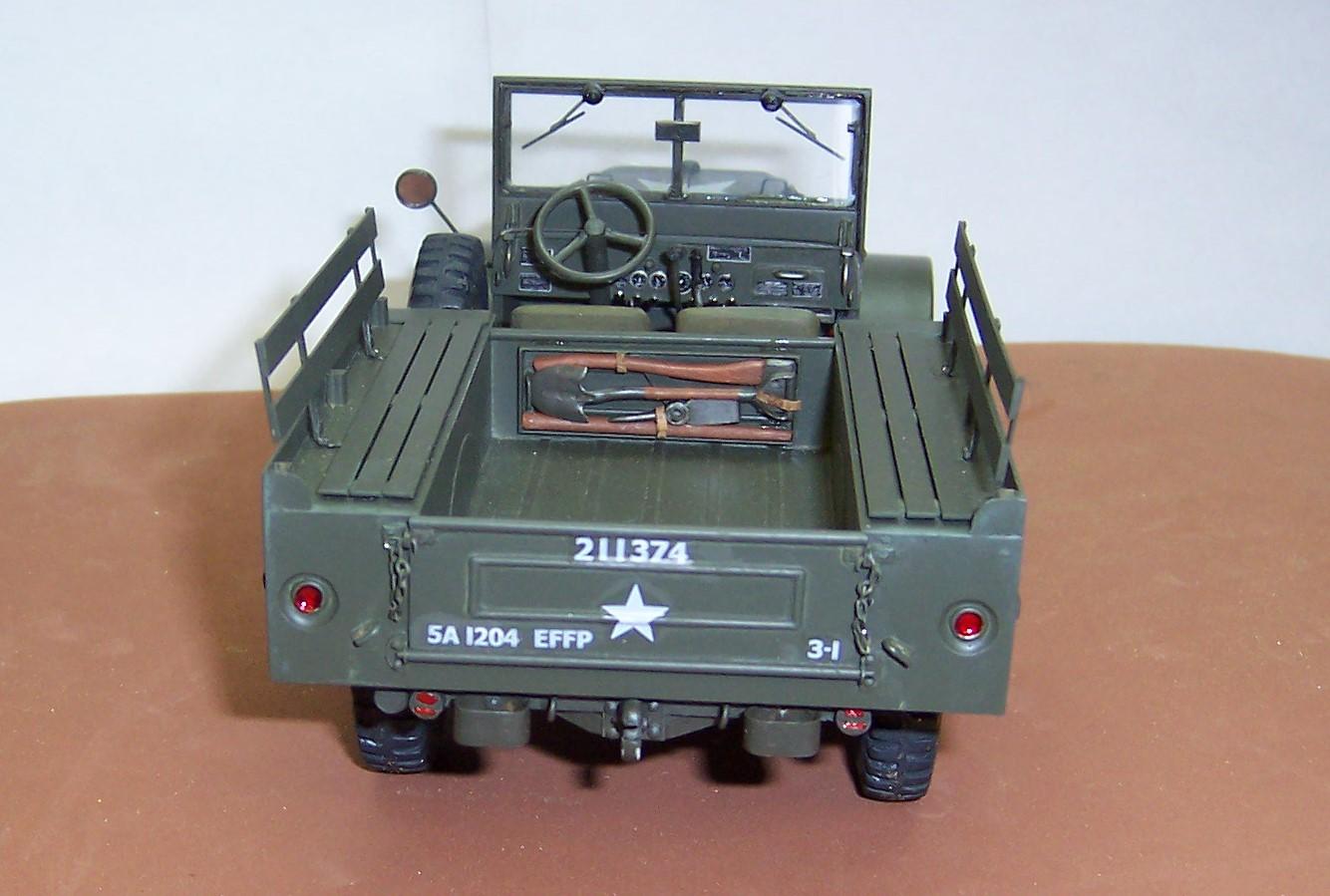
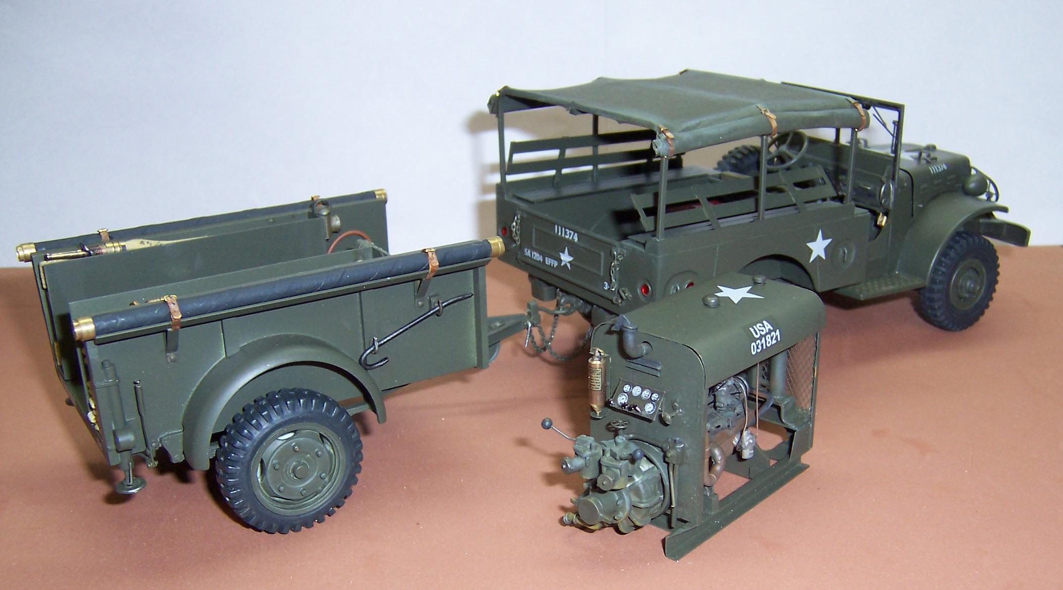
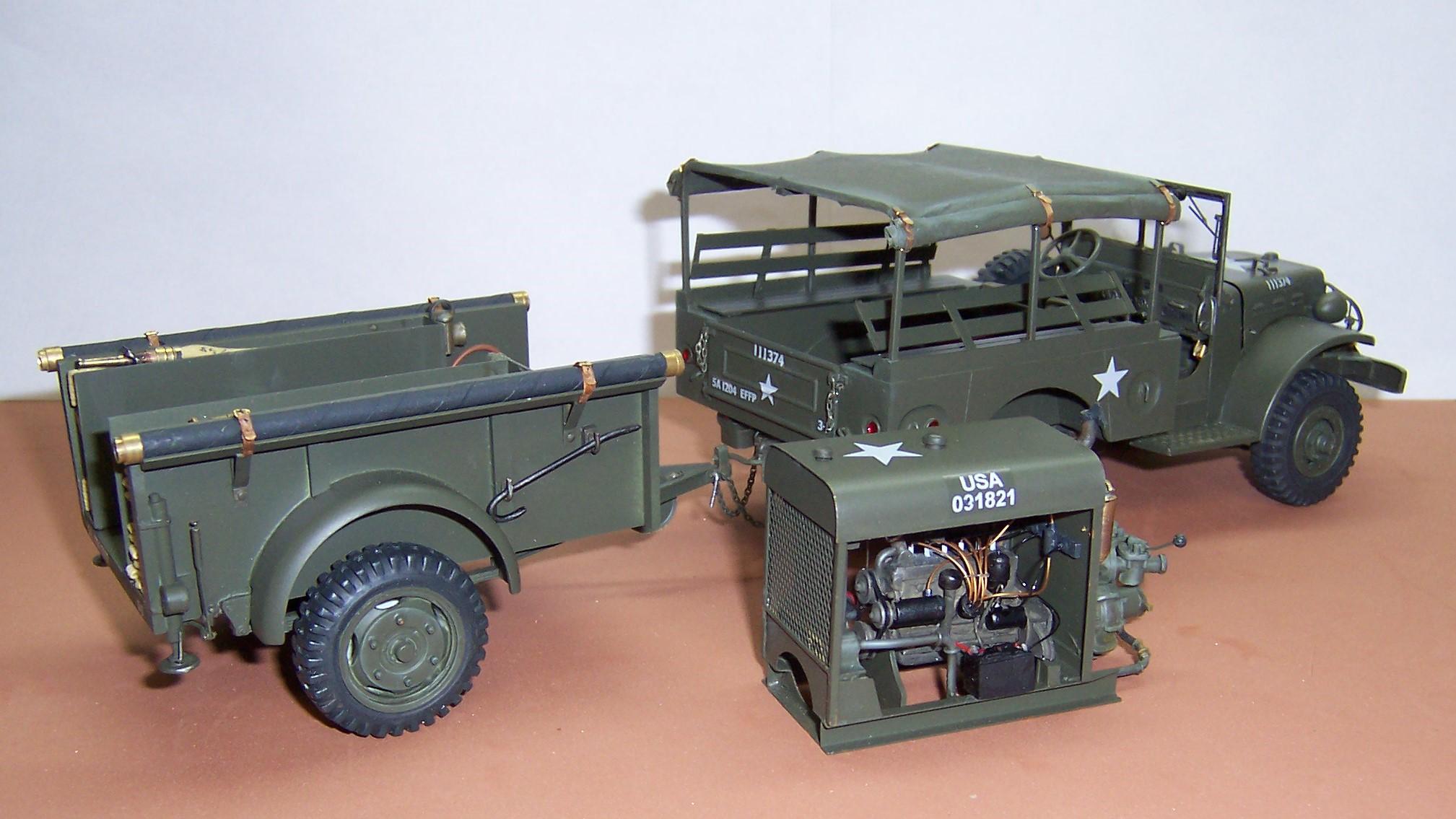
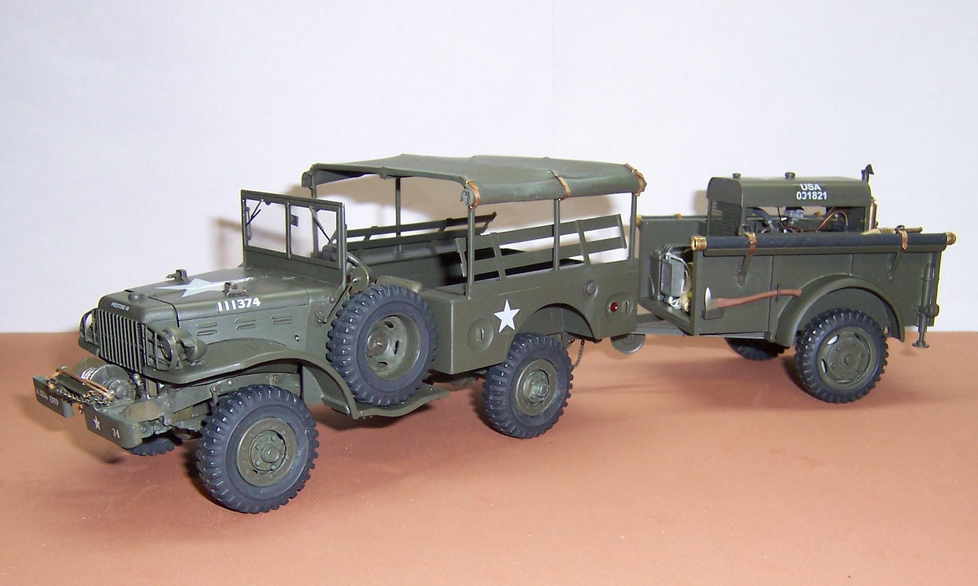
These two are now done. The last thing to do was to add brake lines for the trailer and a Pioneer kit for the WC.
-
I do the same Peter. I have a small whet stone that can sharpen the blade a little but there is nothing like a new blade for shaving plastic or for BMF. So I replace the worst of the two blades with a new one and use the second best blade for ordinary work.
-
1978 Dodge pickup
Chariots of Fire replied to asfastasu's topic in Model Trucks: Pickups, Vans, SUVs, Light Commercial
That is a super clean build!!! I love the paint scheme and shade of green. Wonderful combination. Outstanding results! -
Looks pretty nice to me! Great job cobbling together all of the different sources.
-
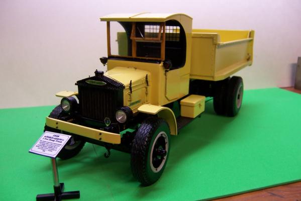
1926 Mack AC Coal Truck
Chariots of Fire replied to Karl LaFong's topic in Model Trucks: Big Rigs and Heavy Equipment
Must have been a day time hauler, right, Keith?? -
What paint did you use on the Ford oval in the grill? I'll bet with a Qtip and some thinner you could lightly swipe the letters and return them to the chrome finish.
-
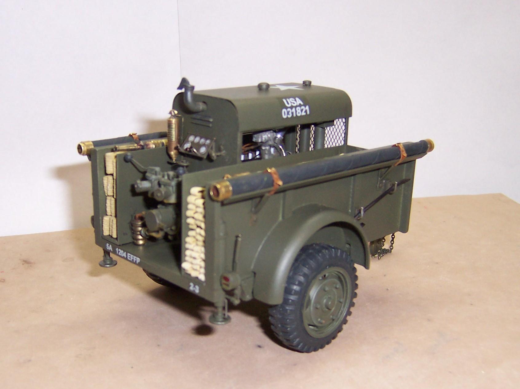
You caught that, eh, Bob? Yes the suction hoses are different. I tried something new this time to make them up. Rather than use castings for the ends I simply chose to use the next size larger tubing cut in short lengths. I relocated things from the first version also. This one has a 5 gallon can of foam concentrate and a pickup tube in the left front corner. The lantern is also relocated. That makes them both unique in a way. Besides, these trailers were made by several different companies during the war and each builder kept to the general requirements of the specs but introduced their own small differences.
-
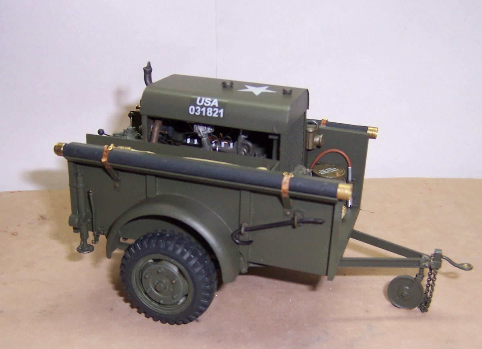
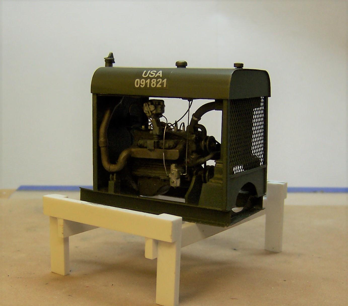
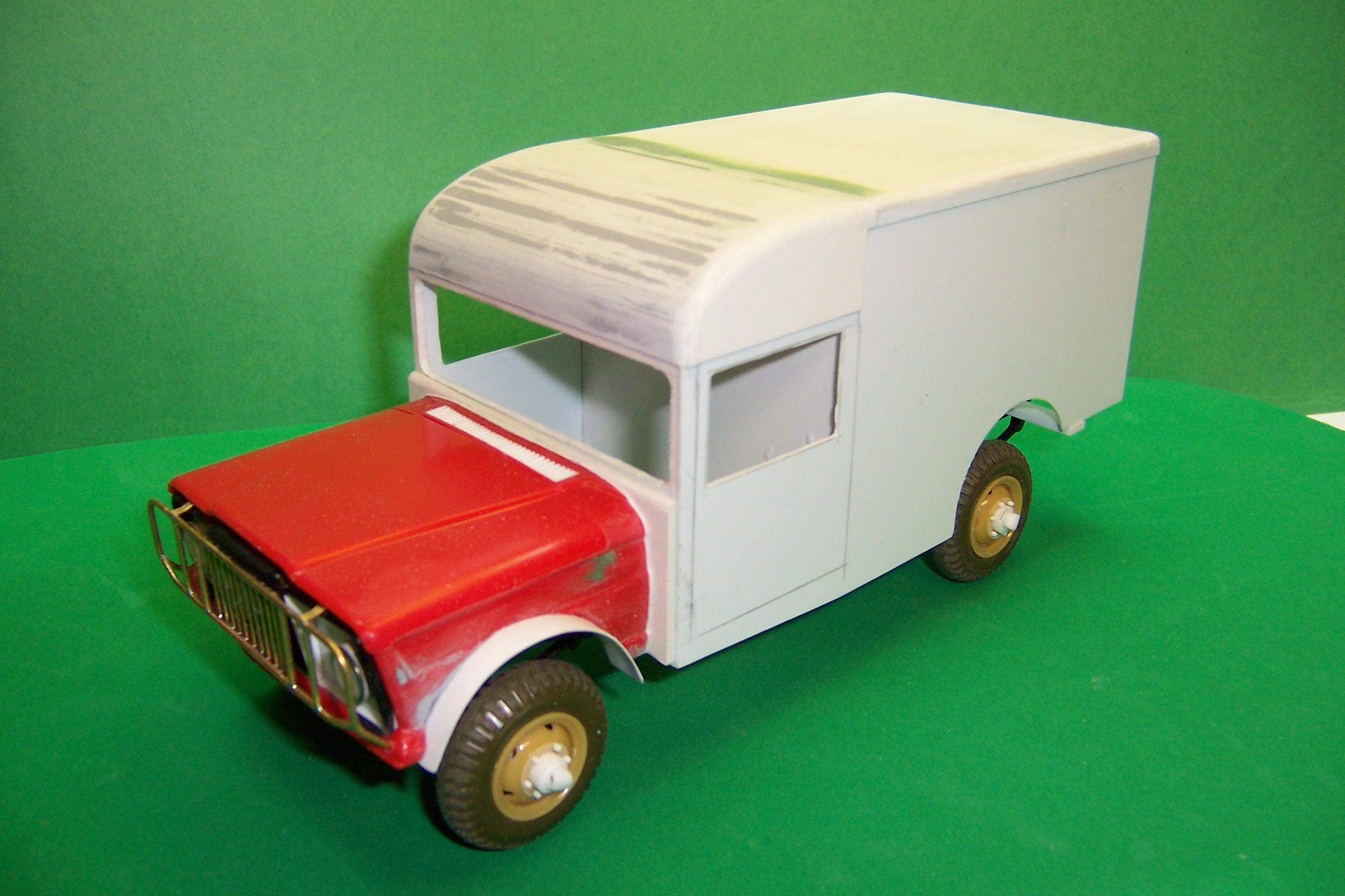
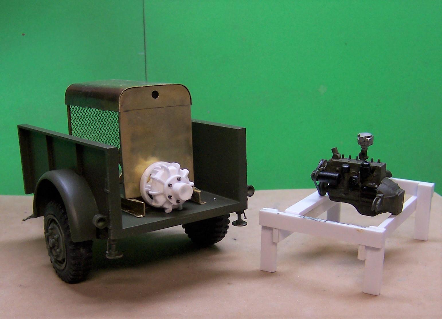
Finally finished up the trailer pump today. Now I can get back to the WC-63 that is supposed to pull it around. For now the WC-52 is doing that duty. I made the pump enclosure removable so that the details could be seen. When it is inside the trailer it all but disappears.
-
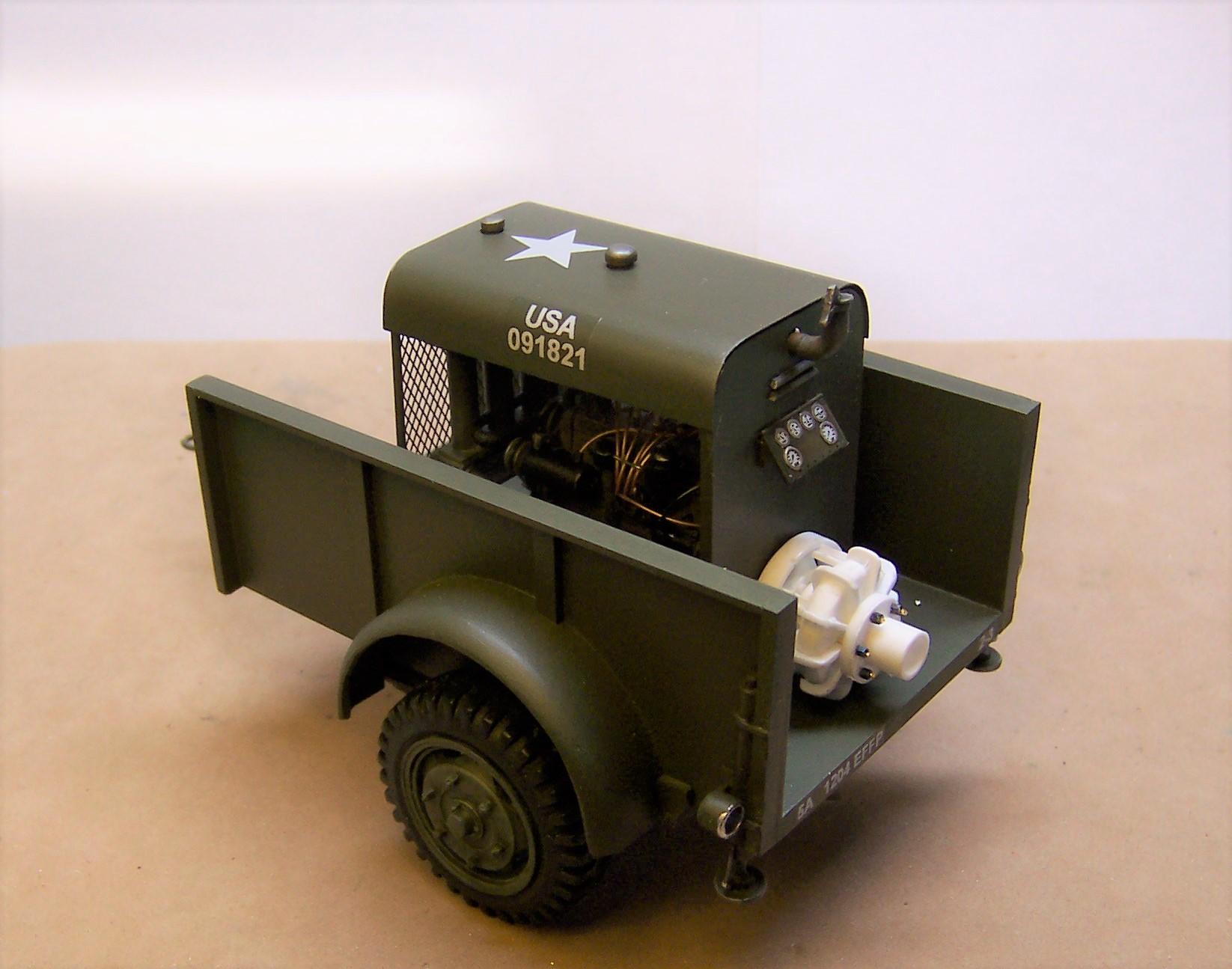
Got more work done on the pump enclosure and the trailer. Most of what is left to do on the pump is detailing it and attaching it to the end of the engine.
-
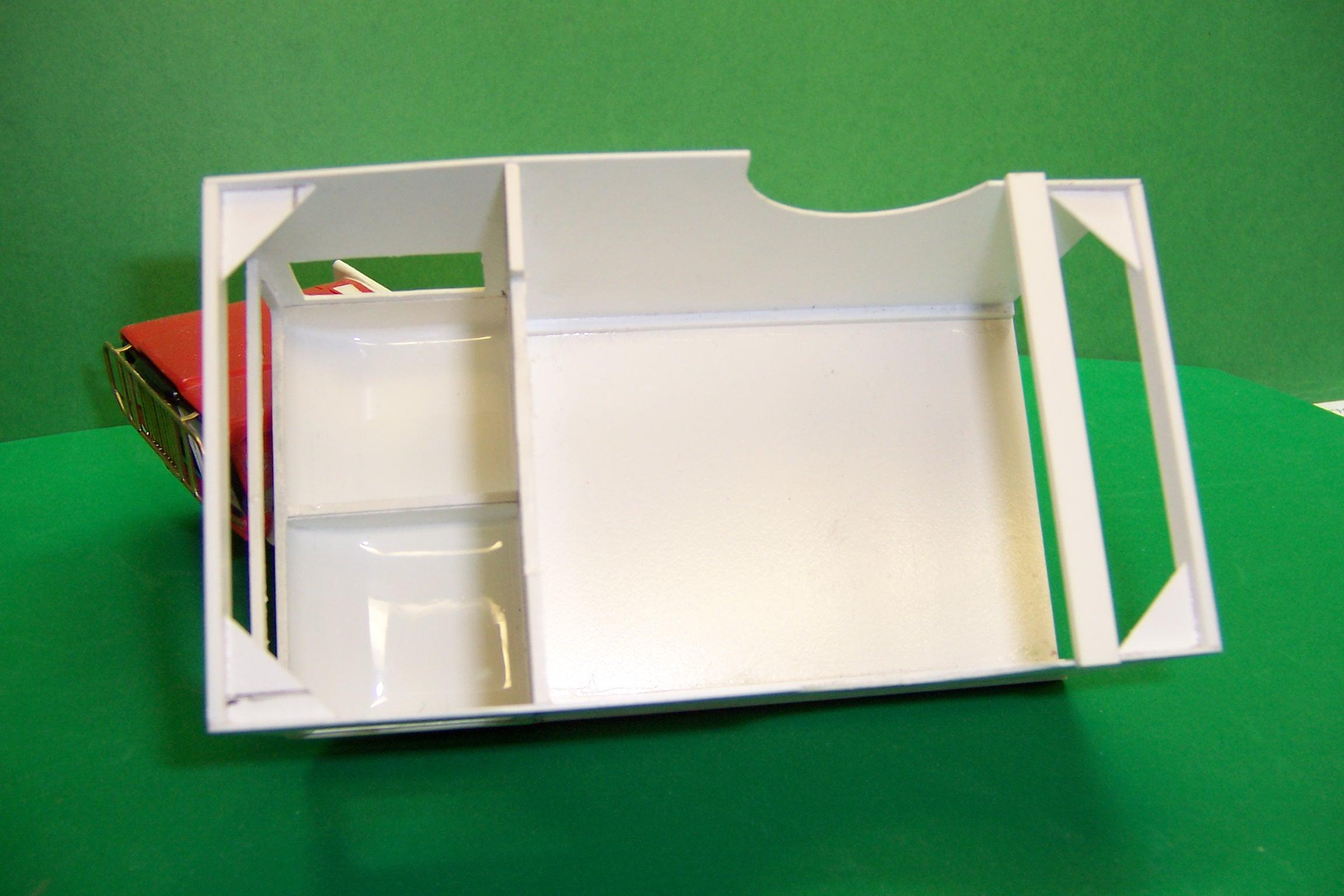
Hey, Bob. Think about trying this. use long strips of thin stock, say 0.020" and glue them longitudinally across those forms. When they are all in place sand them down and fill in the gaps with putty or CA and sanding dust. That keeps the curvature and makes it really strong. Here's an example of what I mean. Those are all individual strips across the top of the body above the windshield. Then they were sanded smooth. Here's what I did inside. I mixed up some two part resin and poured it inside the top and sloshed it around until it started to set. This made the inside just as smooth as the outside. You should be able to adapt this method to what you are doing. Just glue the strips to the two end bulkheads you have and use the in between ones just to hold the line of the strips. Glue around them and then remove them when all is done. Then you can fill in the gaps. Let me know if this helps.
-
The brass sheet was annealed first. Then I used a piece of brass tubing to roll the brass sheet against. So now the top is pretty soft but there's no reason why it can't be. I'm going to put some Archer rivet decals on the end piece and over the top a bit. On the trailer the tail lights need to be finished as well. paint the inside silver first, then fill in with two part epoxy. Then paint with clear red. Then put an OD decal over the whole thing to mark the oval light lens and the blackout light slit below.
-
It matches your shirt, JT!!?
-
Stay safe you guys. You've certainly had your share of rain.
-
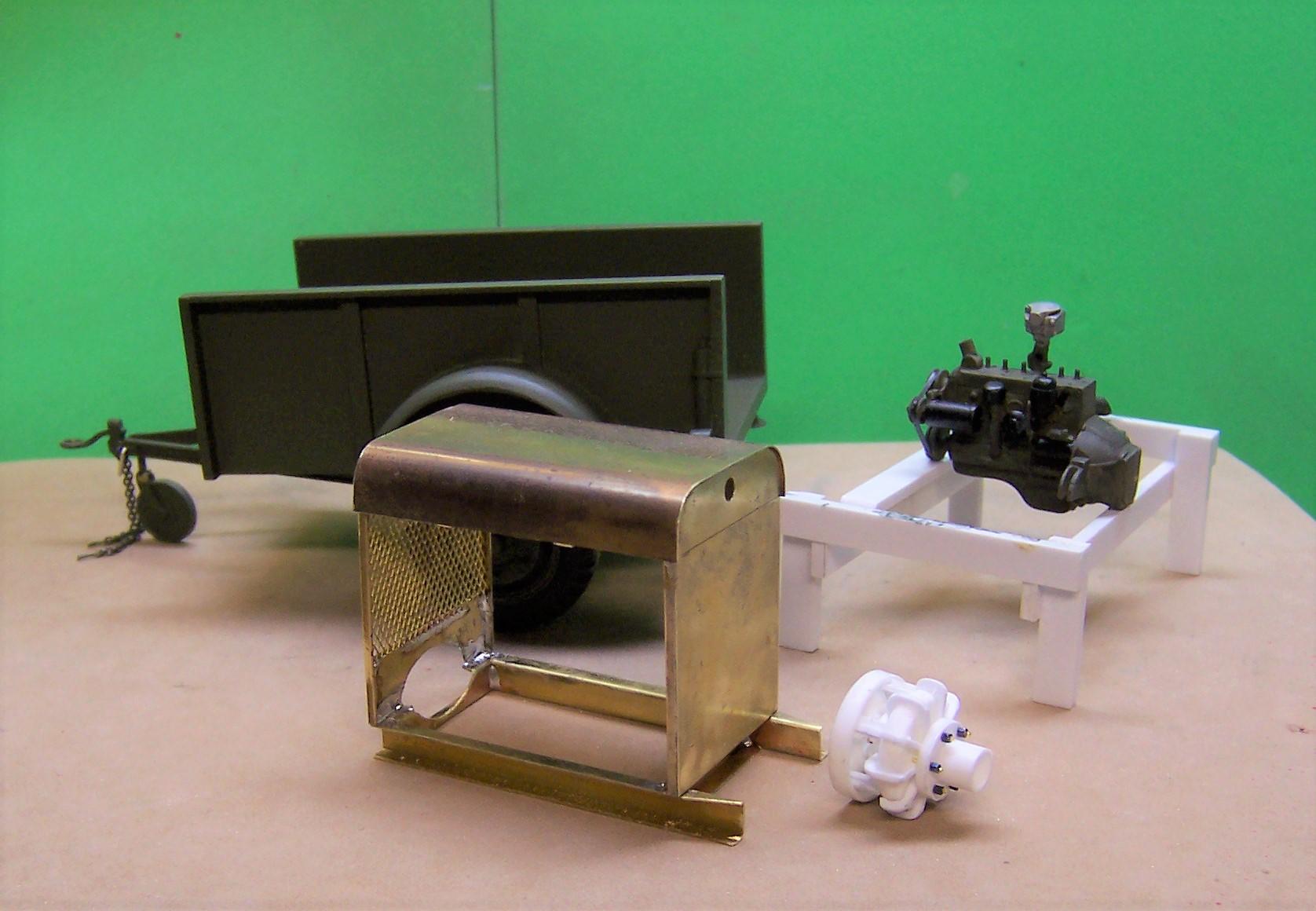
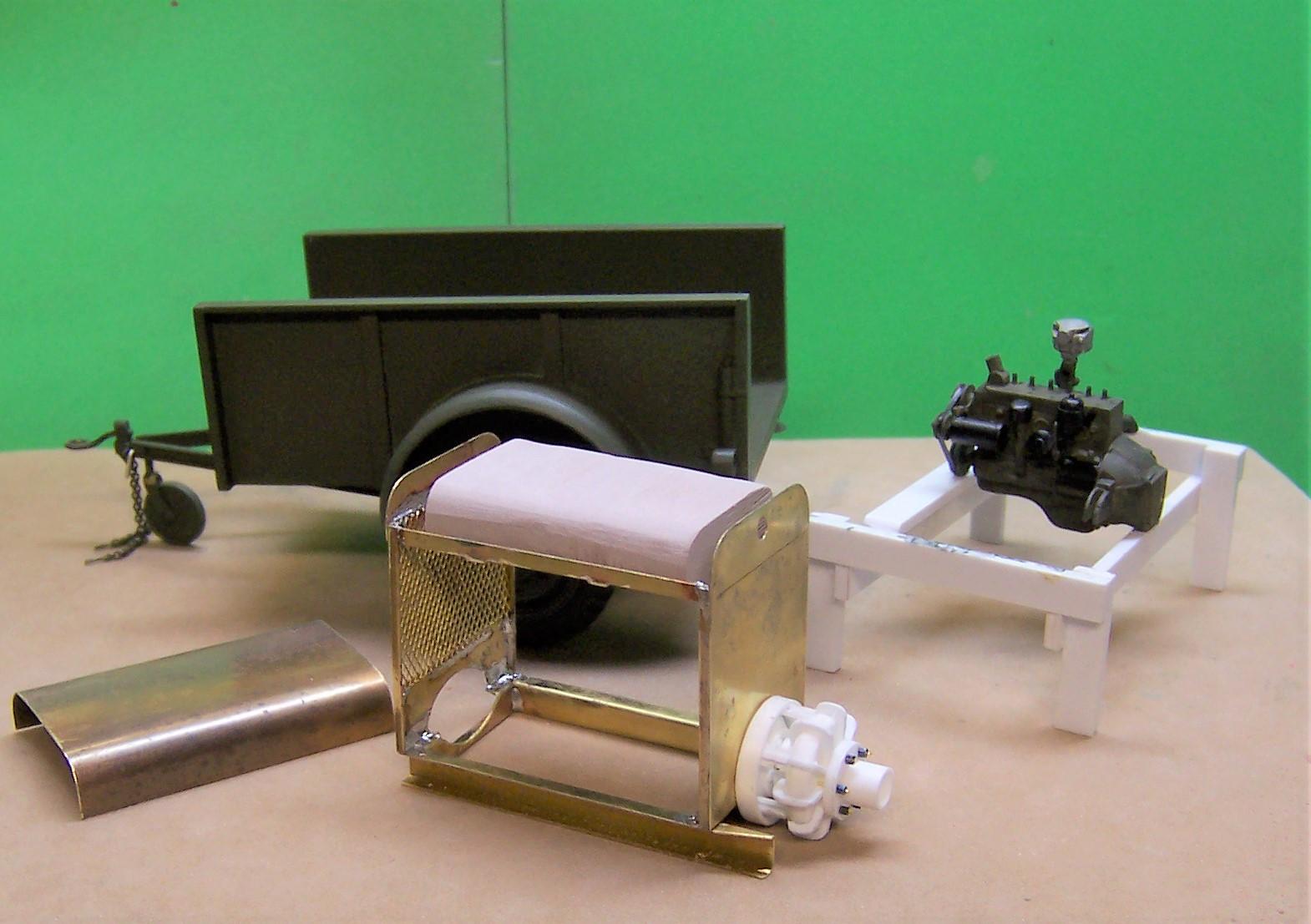
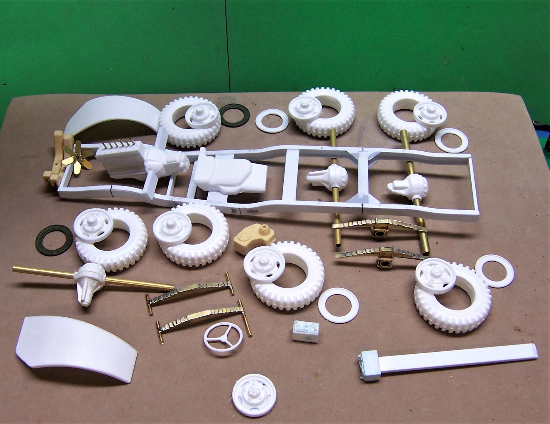
Been working on the engine, pump and pump enclosure for the Class 1000 fire pump that the WC-63 will tow. The trailer is nearly done. The pump enclosure is all brass stock. The engine is the T214 that Dodge provided in just about all of its vehicles in the WC series as well as for the fire pump. With there being only one engine type to service it made things a bit easier. The pump itself is a Hale centrifugal 500 gpm unit. The fuel tank is roughed out Ren Shape. The filler will be through a cap on the top of the enclosure cover. It is gravity flow to the fuel pump and then up into the carb. Engine exhaust will be up and through the hole in the end of the enclosure. In the second photo the pump is where it will be located. The shaft from the engine runs through the face of the enclosure and is direct drive to the pump. Here's the location of the pump enclosure in the trailer. Since the last posting there has been a lot of gathering of materials to use on the WC-63. Recently the rear springs were made up along with a portion of the parts that make up the trunnion. Six radius rods will need to be made as well as a connecting rod that holds the springs together on each side of the frame. Ever wish you had a six volt battery in your parts box but could never find it? I made one up from strip stock and small pieces of plastic rod, glued it to a strip of plastic and plunged it into a glob of blue clay. I sprayed the battery with mold release before doing so. That kept the clay from sticking to the battery master. Carefully pulling the master free so as not to distort the clay I poured the cavity full of 2 part resin and let it cure. That's the casting in the lower center of the photo with the master on a stick beside it. ?
-
I'm with ya on that. Good looking screen. Mine is brass but looks quite similar. I like using odd stuff and I'm always on the lookout for items that can be used to benefit scratch building. Craft shops and even sewing and fabric shops are great places to get materials. Have you seen the new package of tiny brass tubing by Trumpeter? Next time I'm at the LHS I'm picking some up. Four different sizes with pieces about 6" long and they telescope.