absmiami
-
Posts
4,860 -
Joined
-
Last visited
Content Type
Profiles
Forums
Events
Gallery
Everything posted by absmiami
-
 Warm ? WARM ?? It’s 82 right now - 11:24 PM. If you are set up in your garage - and it is not air conditioned - I’m guessing you are doing most Of your machining in the early morning …. Unless you’ve figured out a way to keep the squiters away late at nite …. Nice work. By the way …
 -
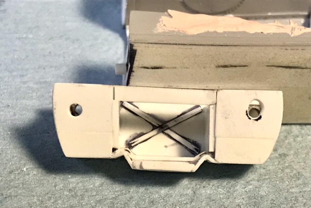
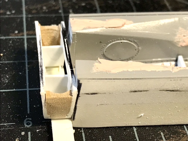
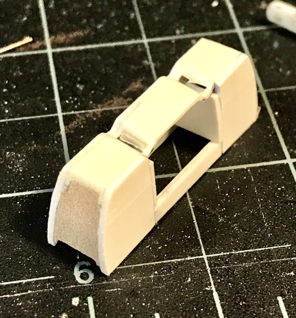
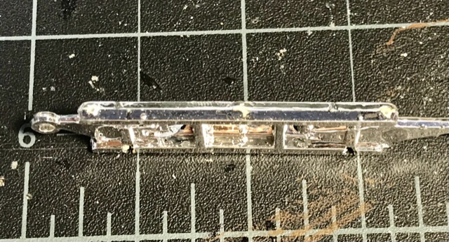
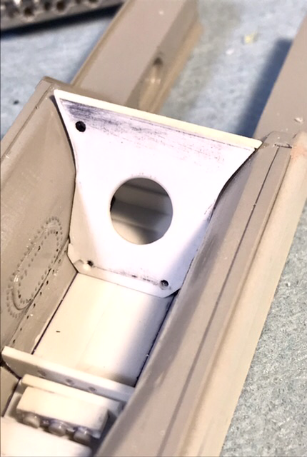
Back fr vacation and back to work - corrections to the bulkhead and some added detail - I’ve added short pegs so the I can get a reliable bond to the monocoque - which also needs some corrections …

-
Great call. Pattos makes decals that no one else would ever produce. Leaning towards making mine one of the Sebring entries. Maybe slate blue …
-
Alfa Tipo 33 (Periscopia)
absmiami replied to Dave B's topic in WIP: Other Racing: Road Racing, Land Speed Racers
Wheels look good. I think you mite have something here … -
And they are not cheap - but Profil24’s D type kits are really, really, really good …
-
Yes. Very nice. And by the way. The Ecurie squad raced a short nose too …
-
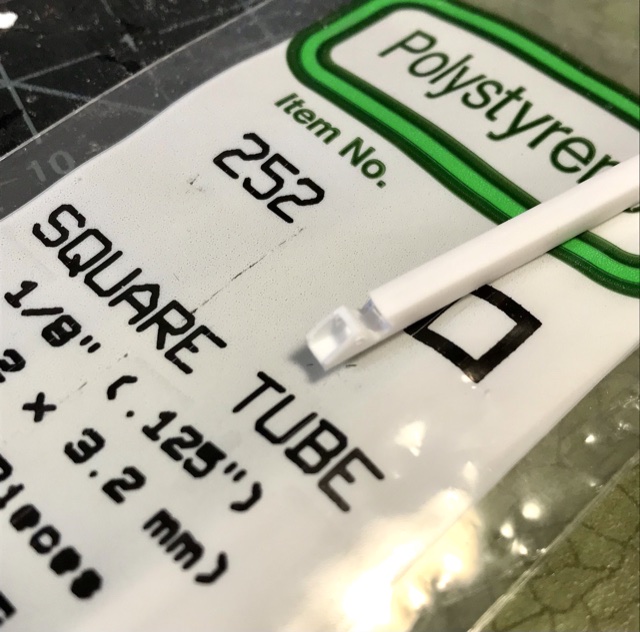
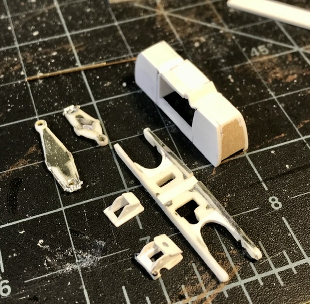
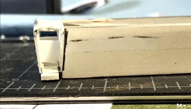
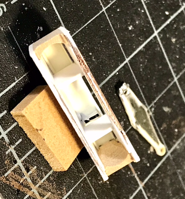
The pedals were suspended from housings riveted to the bracket that the rockers pivot from … same arrangement as on the Lotus 25 …. These were made from filed Evergreen square stock and strip … the kit part had two lumps without any real features …
-
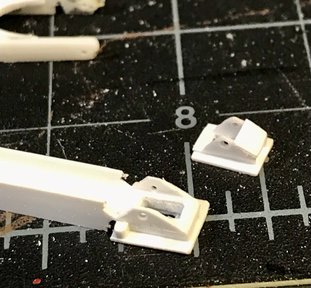
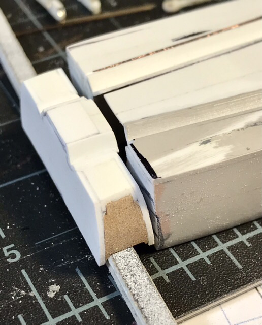
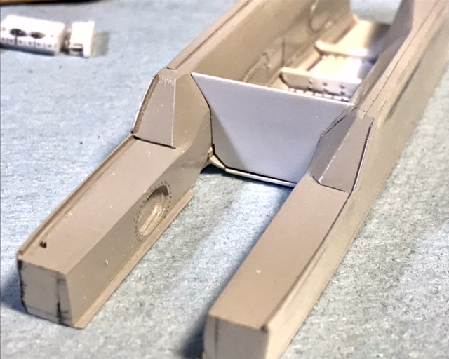
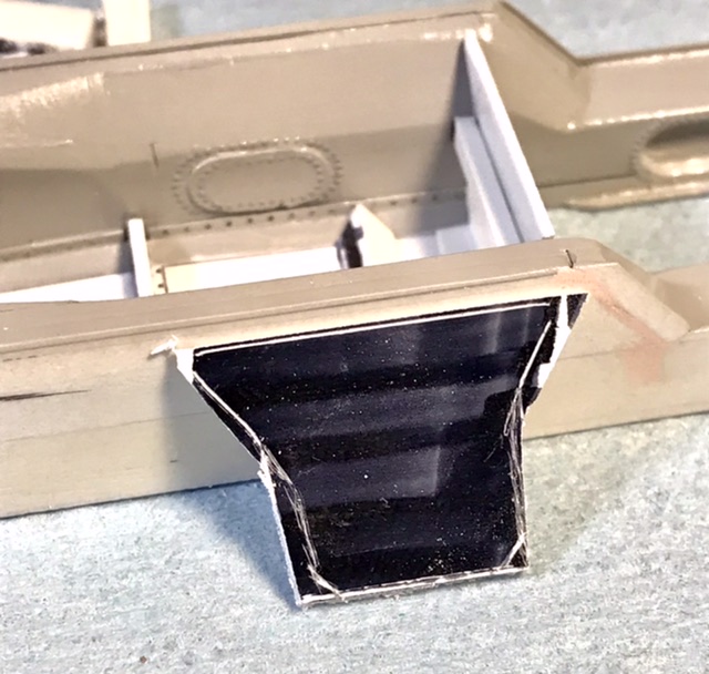
Some changes to the base of the pedal box to better match the run if the pipe cutouts on the base of the monocoque …
-
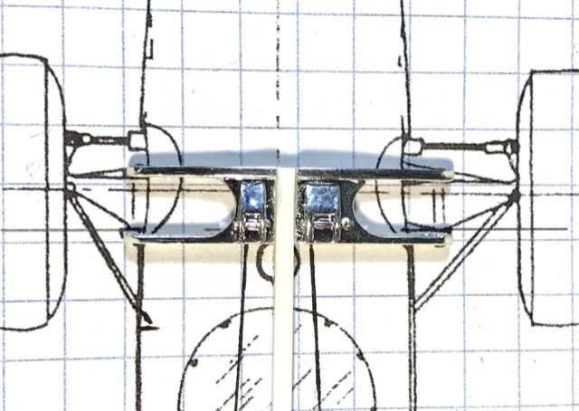
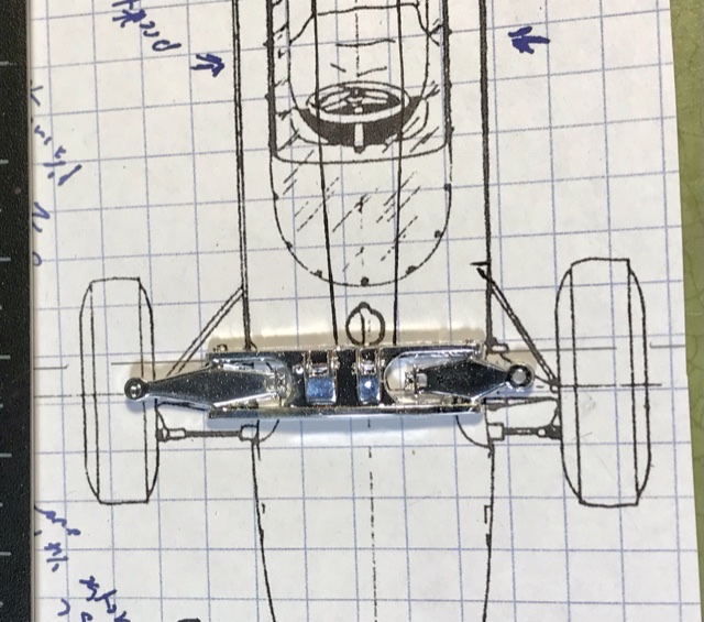
Good to hear that you got your son interested - my kids got game boys when they were ten and it was all over …. Any way - the rocker arms - the right side arm may be a scale inch too long - gonna have to do some more assembly to make sure that I keep the wheelbase correct …
-
We could start a chant … Lola , Lola, Lola, Lola … ?
-
And a happy Father’s Day to all who encouraged their sons to build model kits …. How’d THAT turn out …. ??? ??
-
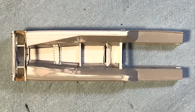
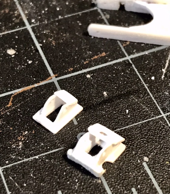
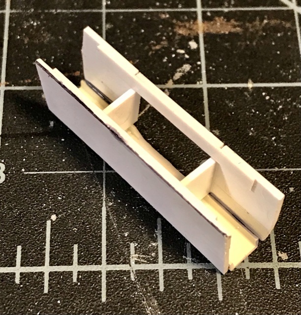
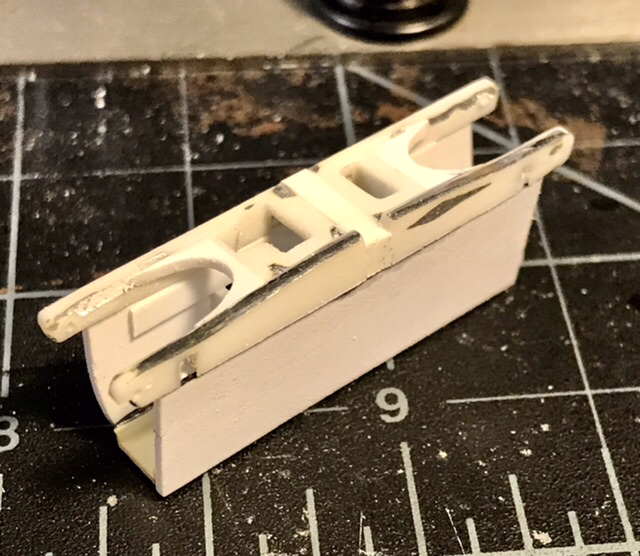
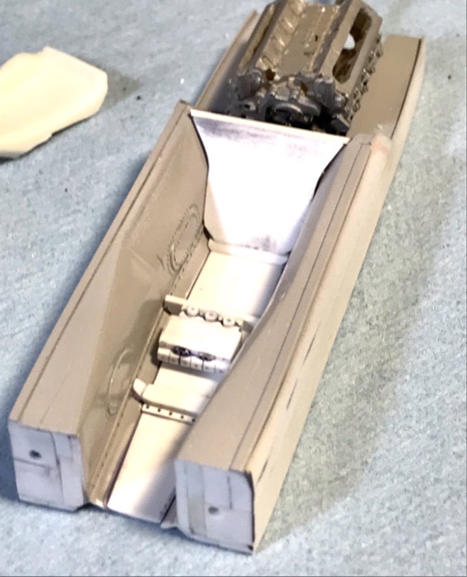
This was made with sheets and strips of Evergreen - .020 and .030 with a channel strip at the base - all liquid glued together and finished with sanding sticks. The brown parts left and right are some bits of renshape …
-
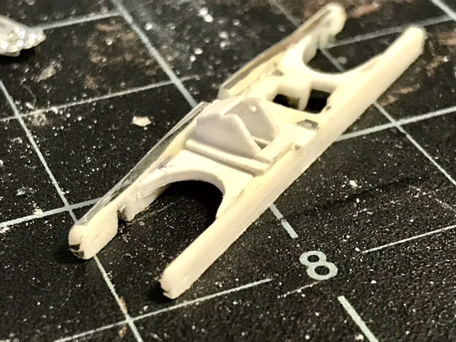
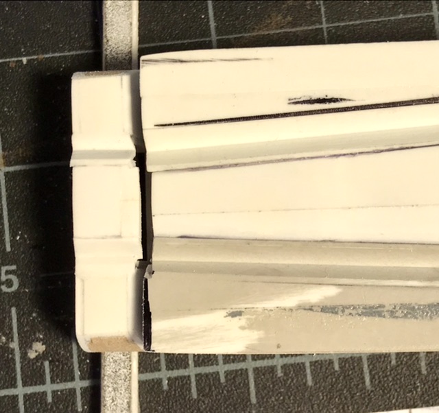
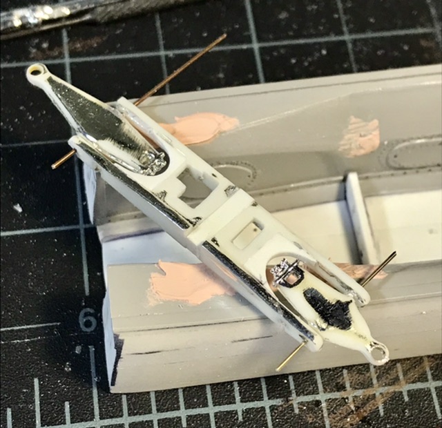
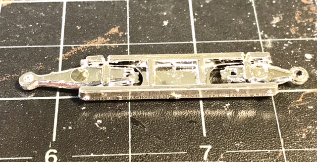
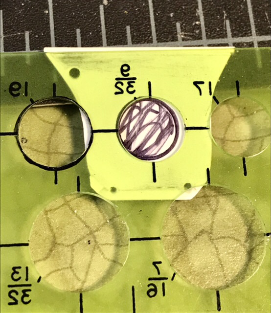
Time for the pedal box / rocker housing bulkhead - which is separate from the monocoque and has a taper top to bottom - so the base is narrower -
-
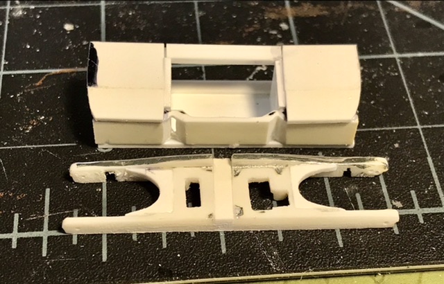
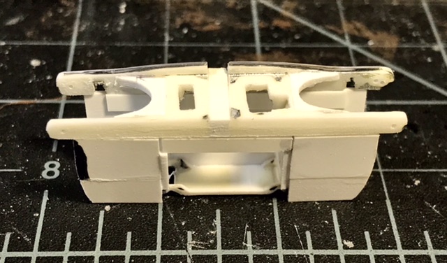
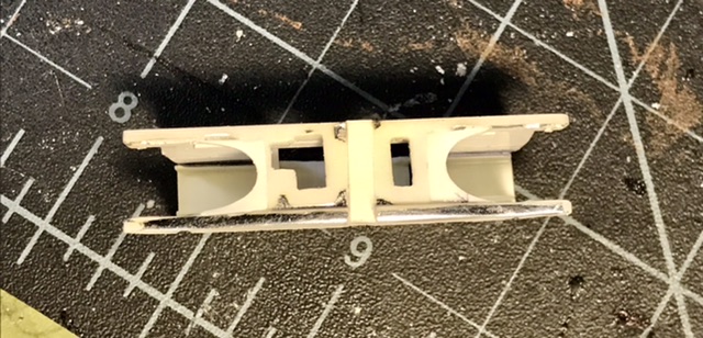
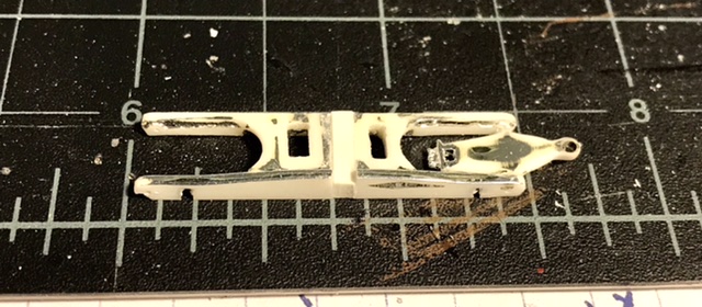
Lewis Hamilton wants that third set of tires about now …. Re-shaping the profile of the cover of the rocker housings … and opening the holes for the pedal arms …
-
What would happen if you tapped on a razor saw to emboss a pattern ? Similar effect …. ??
-
Looks good …. What tools are used to emboss the seat pattern ?? ???
-
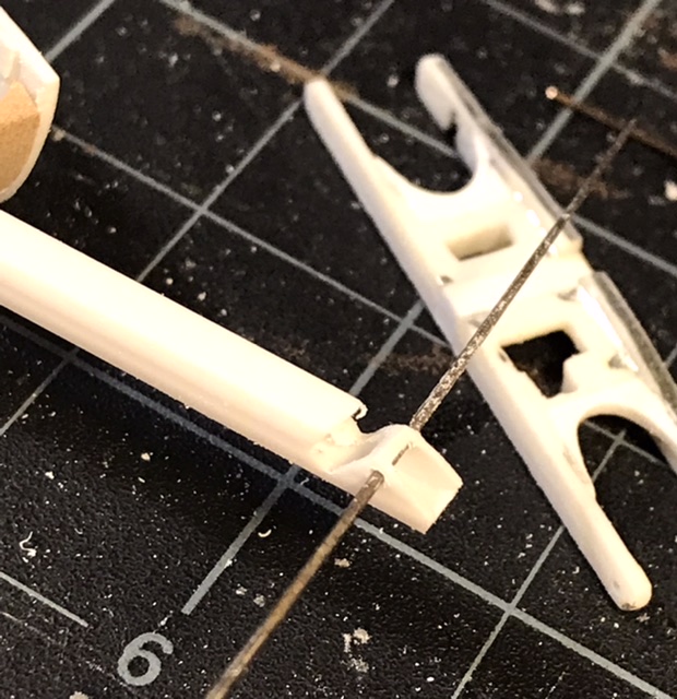
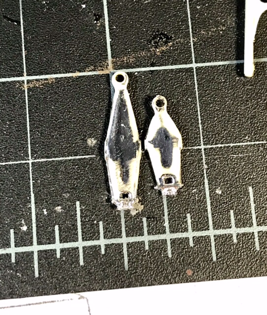
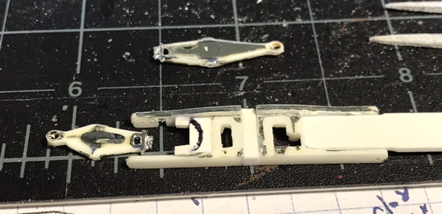
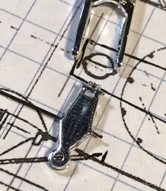
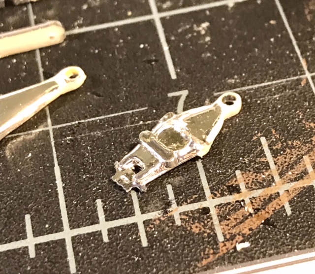
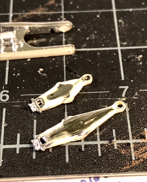
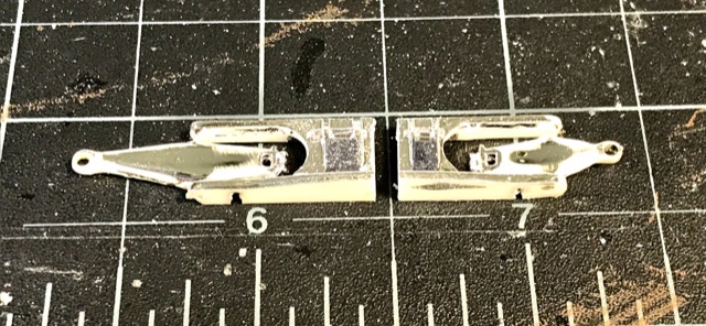
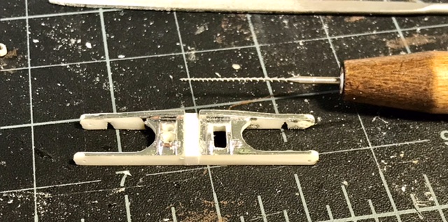
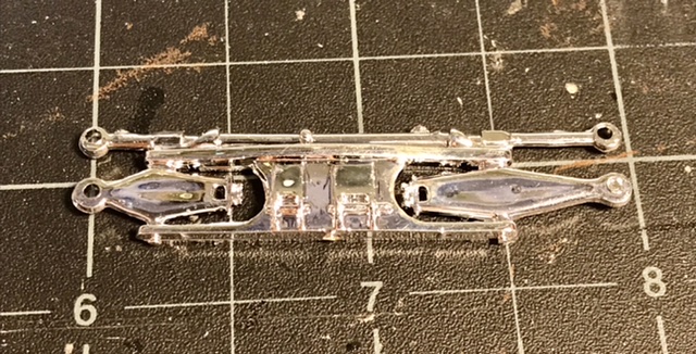
The rockers are sawed off and drilled for .05 pins - the arms are correctly shaped - but need some mods to reduce the size of the upright locating rings and remove some inaccurate under-side casting features …
-
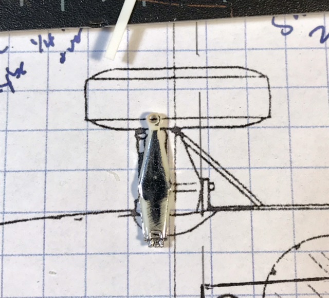
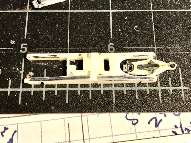
To the forward Bulkhead …. The 29 used an offset suspension with different length rocker arms. The kit part has some accurate detail - but I’ll have to lengthen it to use it in 24th scale - again using the Clidinst drawings …
-
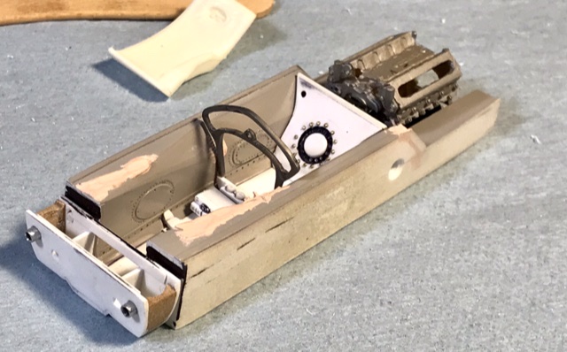
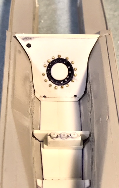
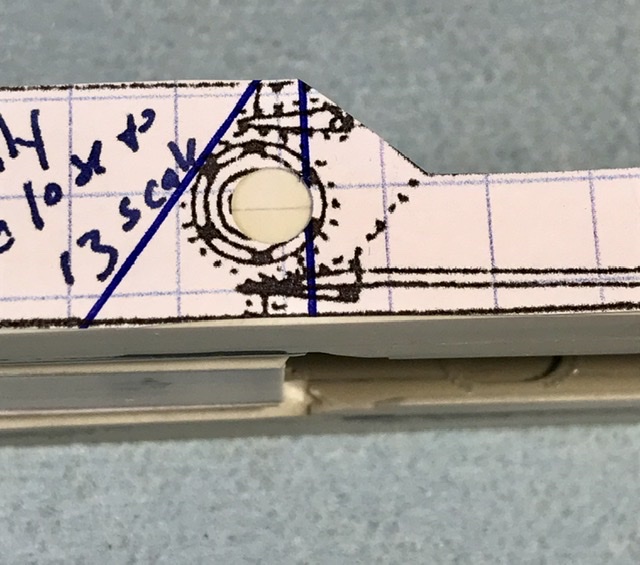
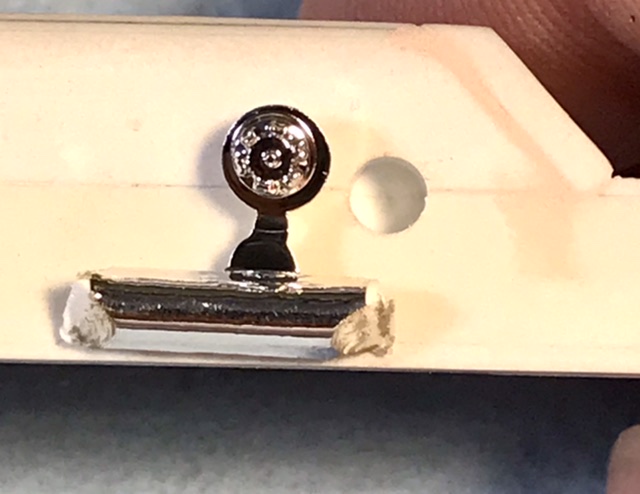
Rivets for the fuel tank bulkhead …. And using the Clidinst drawing to locate the fuel filler …. The AMT kit fuel filler cap mite be usable with the chrome stripped off - with the removal of the filler ring - the cap is casted off- center …
-
Thanks for buildin ... !!
-
Well they didn’t really corner …. If the track wasn’t banked - they just slid …. I grew up 4 miles from the Langhorne Speedway. But the track was winding down when I was a tike and I never got to see a race there - to my regret …
-
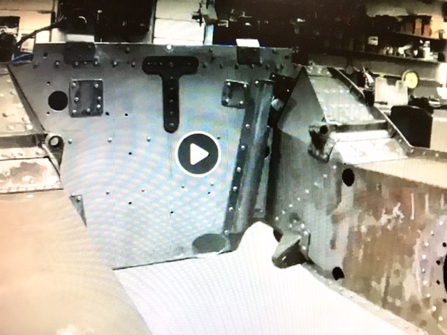
The videos also show us the shape and location of the engine mounts …
-
The engine and seat bulkheads first - with some detail added per the Indy Museum resto …
-
Got to make the bulkheads - now that I know exact width / profile …