Farmboy
-
Posts
518 -
Joined
-
Last visited
Content Type
Profiles
Forums
Events
Gallery
Everything posted by Farmboy
-

Another 3100...4 door duallie
Farmboy replied to Farmboy's topic in Model Trucks: Pickups, Vans, SUVs, Light Commercial
Thanx Greg. Its done, but now I think I may add a few details and then some wear n' tear. We'll see when I get some bench space. -
Another 3100...4 door duallie
Farmboy replied to Farmboy's topic in Model Trucks: Pickups, Vans, SUVs, Light Commercial
Thank you Zippi -
Another 3100...4 door duallie
Farmboy replied to Farmboy's topic in Model Trucks: Pickups, Vans, SUVs, Light Commercial
Yer right Tony, too clean for a work truck. I was thinking thinned oil paints for chemical stains, lots of paint chipping and dirt. It'll happen. Thank you Happy, sometimes I get lucky and a model mod works out. -
Another 3100...4 door duallie
Farmboy replied to Farmboy's topic in Model Trucks: Pickups, Vans, SUVs, Light Commercial
Well Kurt, the majority of parts went to the parts box, a grille ended up on a custom '49 Merc, one of the xtra curved windows fell victim to a dachshund spite attack, the 2nd truck box is around somewhere, I have another parts box I've yet to find since the move...and the beat goes on lol. I finished this awhile ago but I didnt post it till now. Thanks much for the shout out. -
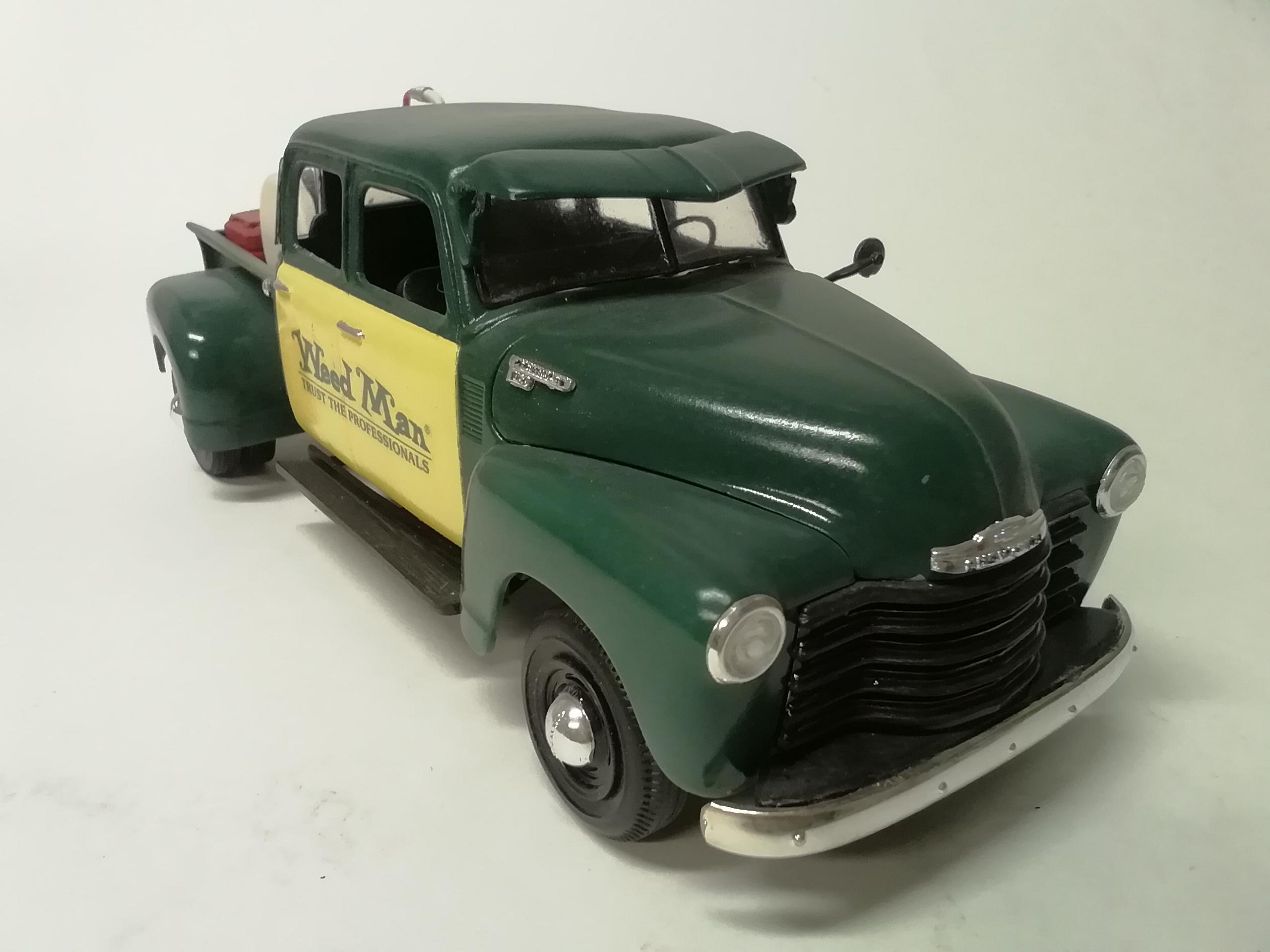
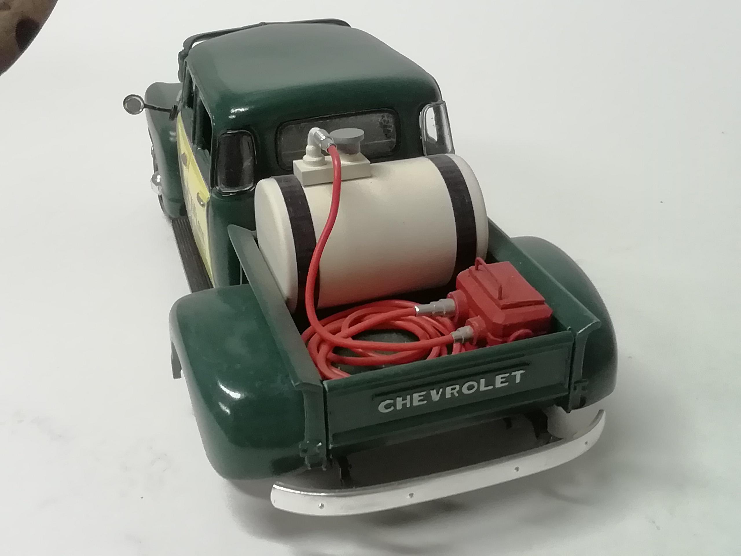
This was a clearance item at Walmart, bought 2. One day I got the idea to merge them. Decals home made from an actual invoice. Spray gear fabbed from a 35mm film canister, sprayer assembly from wire and circuit breadboarding post, and a modified backpack from a dollar store figure makes the pump. I'll weather it someday when I learn how. Comments and observations welcome

-
Mike, at times I felt like Henry Ford himself lol. Thanks Tony. It was an enjoyable build.
-
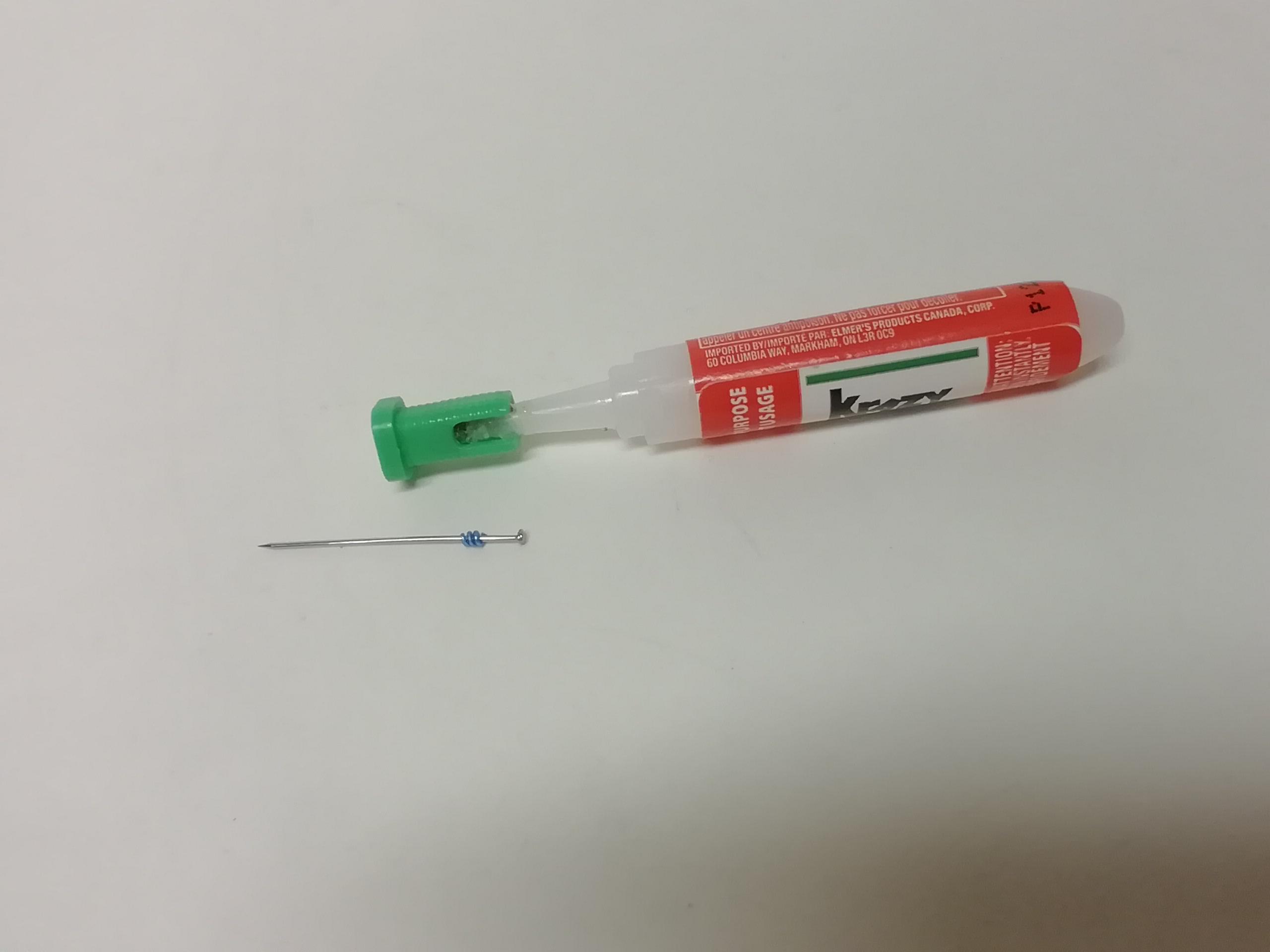
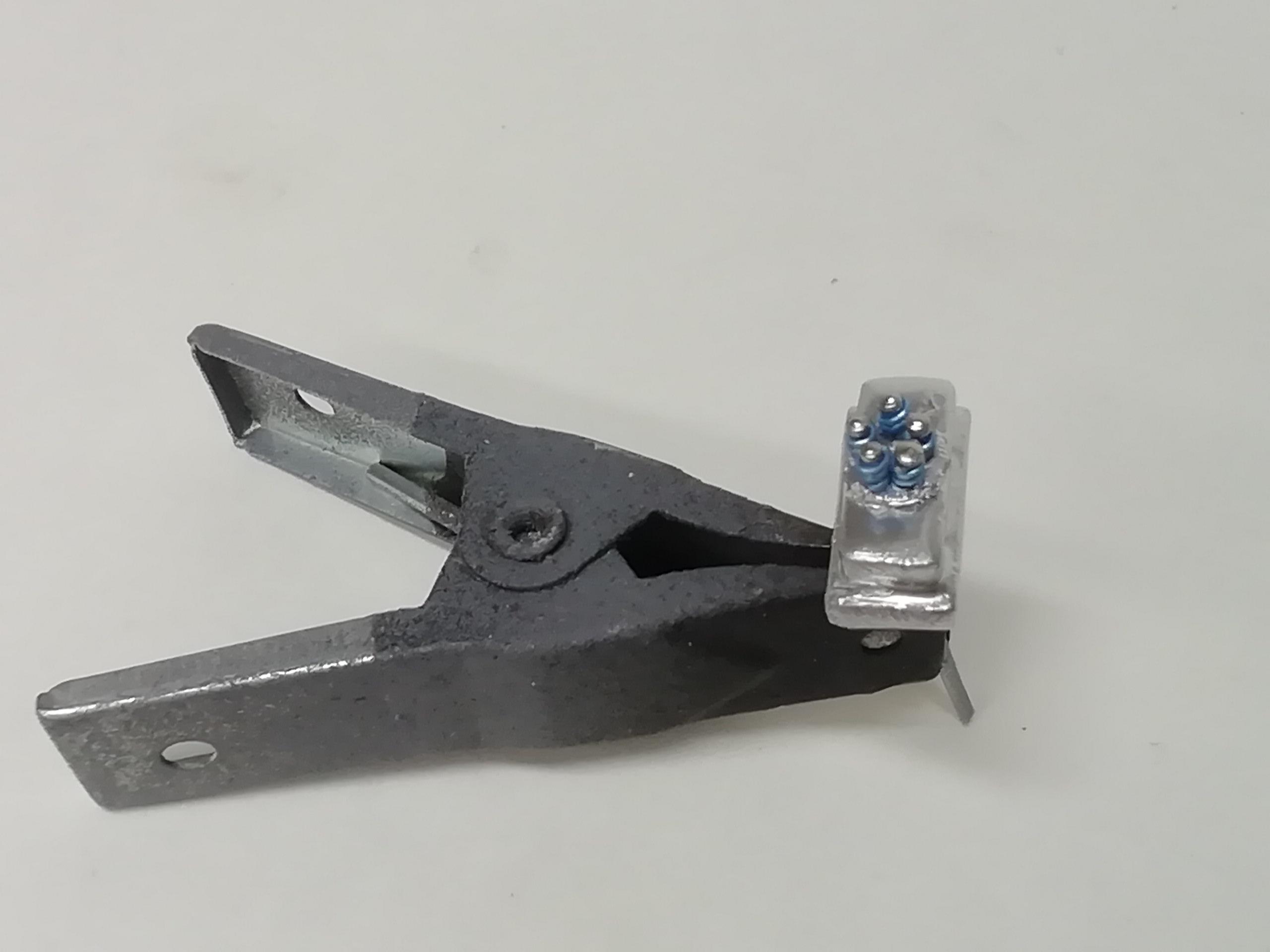
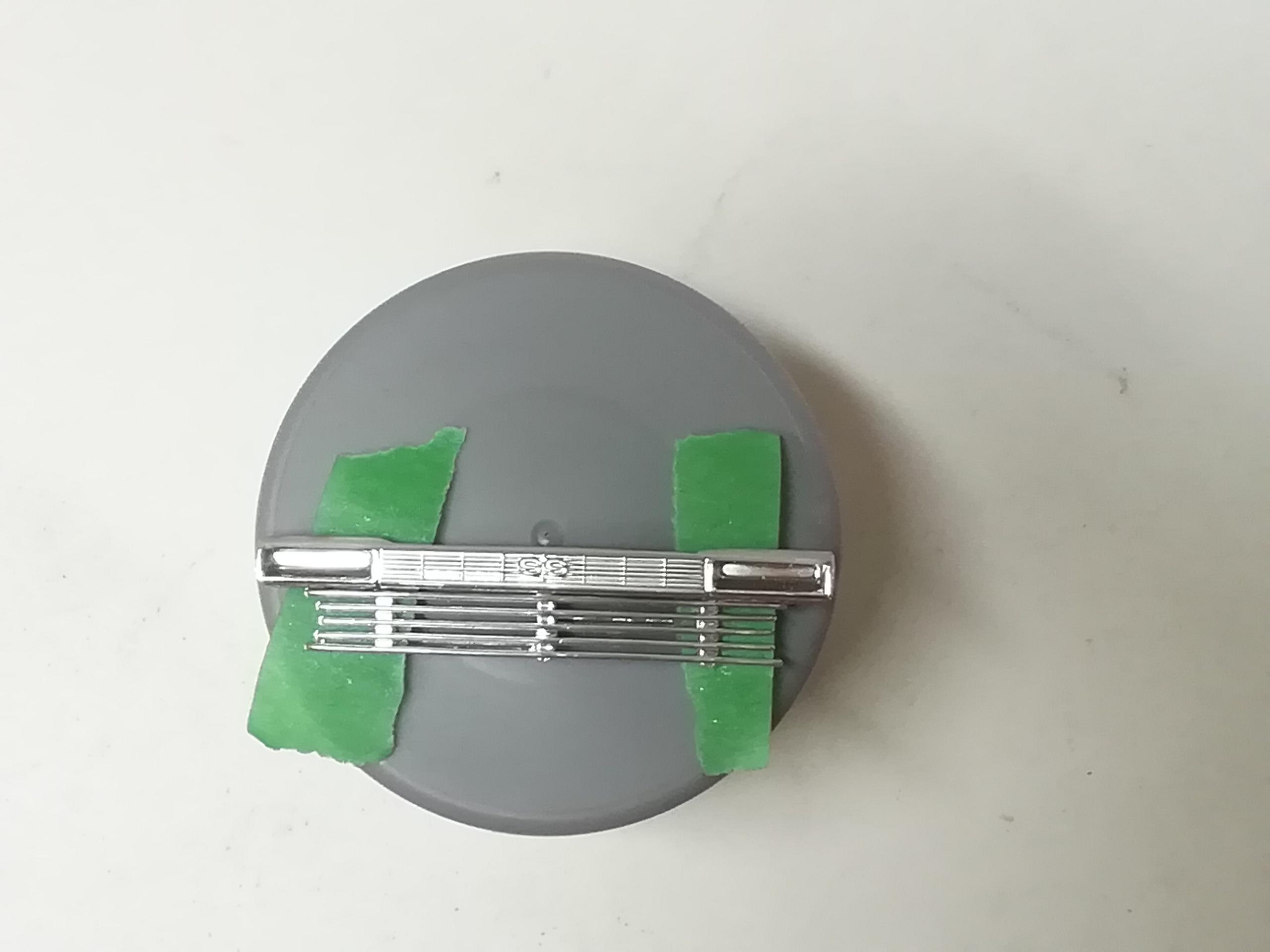
Decided to re-do the pressure plate assembly so, as the process worked for me, I thought I'd post a short tute on how I did it. Tools used were pliers with side cutter, manicure scissors, both gel and thin ca glues of your choice, straight pins, and wire. Wind the wire around the straight pin quite a few times so you have enough to make all the spring units and a few xtra Three turns were enough for my application so using the manicure scissors I snipped off as many 3 layer coils as I needed Slide the coil on a straight pin then add a touch of thin ca just under the pin head Push the coil firmly up against the pin head. It should set almost immediately. Snip the pin to length. I eyeballed the tail length so all were approximate length but drilled the mounting holes deeper than this so the coil stopped all the units at the same height. Try dry mounting each spring unit first, then, add a touch of your choice of gel ca to the tail of the unit --not the hole -- and install in place. I found (for me at least) that this sequence allows for a cleaner mount and also allows last minute minor adjustments before it sets. This is the revised pressure plate assembly. Some minor touch ups from previous work on the case sides and were good to go. One of I'm sure many ways to achieve the same results, thought it may make life a bit easier for some of us. Comments and observations welcome.
-
That I would have had your skill when I had that kit. Nice work and problem solving.. oh, card #11 with a picture of Ilya was the hardest one to get in the trading card series to complete the set lol.
-
This is the first attempt at the pressure plate. I may re-do it if I look at it too long at hi magnification, time will tell. By the time the engine busy's up a bit, and the piece being so small, it probably won't even be noticed anyway lol. Comments and observations welcome
-
Here is an in progress photo of the pressure plate. This view shows the holes on the upper side where the two large pipes connect and go to the injector assembly on the engine. The round piece is the spring base I punched from styrene, then added 5 holes to hold the individual spring assemblies on the side of the unit I chose to make the side injector piece an air intake only, the fuel injection being done on the engine manifold. The tubes were drilled out to leave a slight shoulder on them and giving the velocity stacks a snug fit. I could have probably made the holes larger for a larger diameter ferrule, but this is one of those instances where cowardice is the better part of valor lol. And it presents a clean uncluttered look. Haven't worked out the air and fuel linkage yet but it'll happen. More to come. Comments and observations welcome.
-
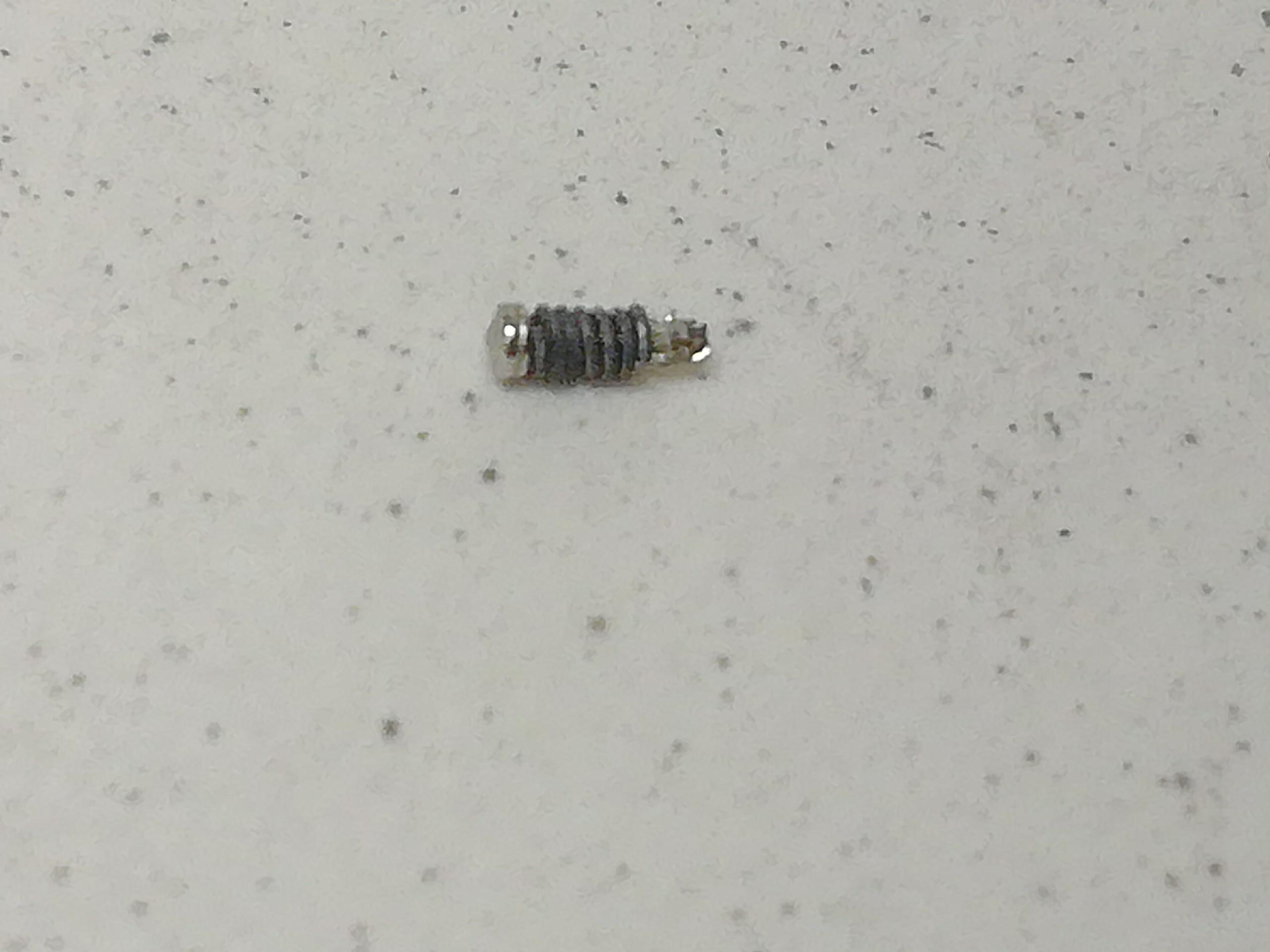
Taking a break from the body and interior to begin the engine work. This vehicle will be powered by a later model flathead with potvin arrangement, the blower coming from the Mooneyes dragster kit with a bit of modding to suit the pulley arrangement of the flathead engine. This is the base assembly of the potvin as it will mount to the front of the engine. Note the drive pulley mounted between the front plate and the blower. I made the front plate thicker to encase (in the real world) the belt or chain that would connect it to the upper shaft that then transfers the engine energy to the blower rotors. I saw this arrangement in a couple of photos from people that wanted to keep the front mounted water pumps. The spacer that separates the blower and plate was fabbed from a short piece of aluminum tube. I merely laid it on a hard surface and g e n t l y tapped it into a rounded rectangle, alternating sides every couple of taps. Once I was satisfied with the shape it was sawn from the tube. I'm planning on doing the fuel injection with the spider distribution block on the engine and not on the blower. It will have the front mounted pump with feed/return lines and the line from pump to the metering block that works in conjunction with the intake. I will try making the pressure relief unit on the other side. This is a super closeup shot of one of the 5 spring retention studs. It's the head of a pin cut to an arbitrary length, the 'spring' is a single strand of wound picture wire. Nasty stuff. Each would mount in separate small holes on a circular plate on the rectangular box on the side of the blower. We'll see how it goes. Time to see if this whole thing fits believably in the bed of the truck. The mock up below shows a sloppy preview. The blower will need space for the front mounted fuel pump, and that puts the transmission end past the transaxle, but no worries. I built the Paul Revere Raiders Coach, and their solution had the driveshaft going to a chain drive transfer unit, allowing another driveshaft to come forward to power the tractor unit with the transaxle pointing backward. Kinda the same just a bit easier hopefully. Comments and observations welcome.
-
Many thanks Paul, appreciate the shout out.
-
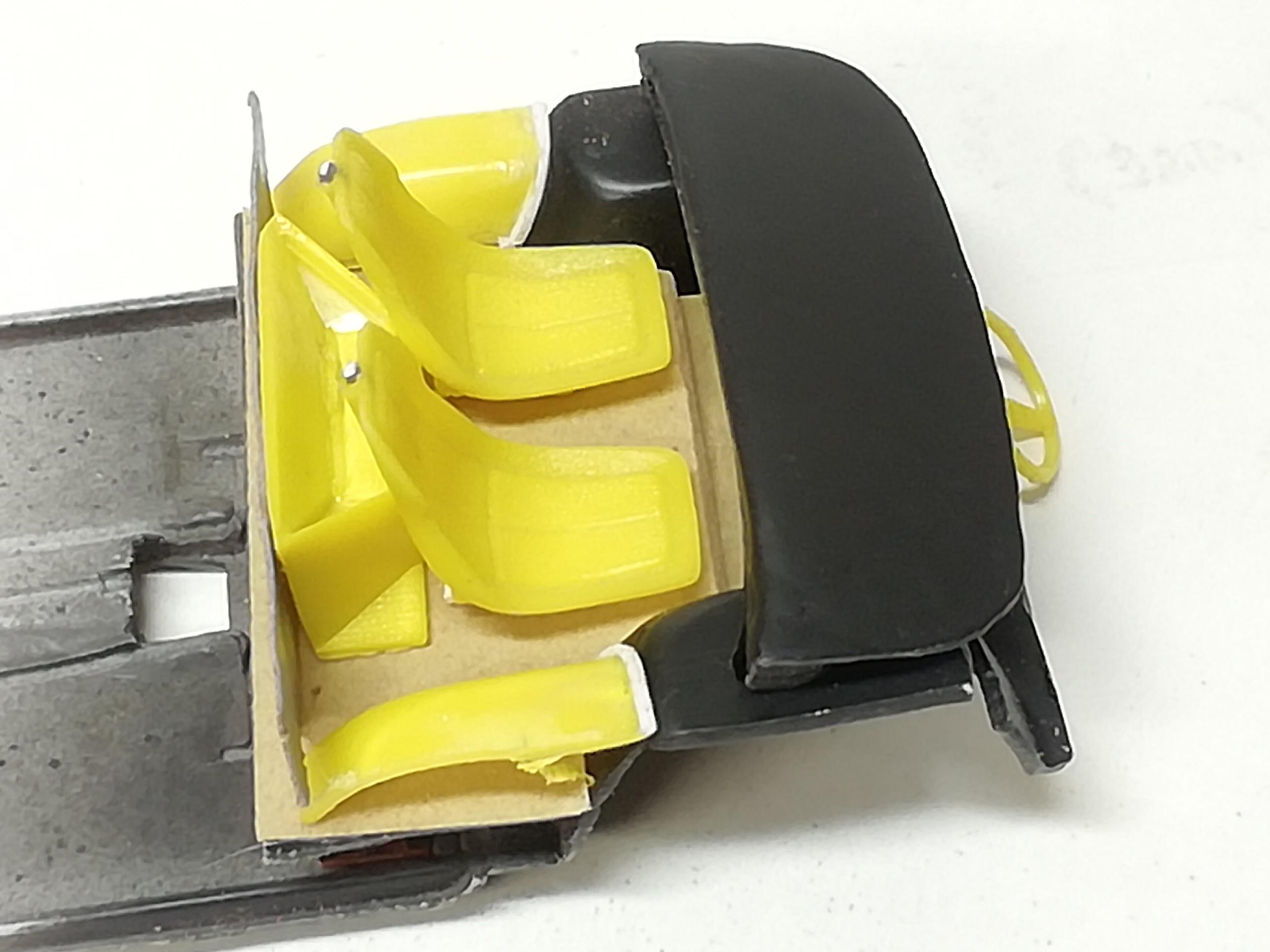
Also got a good part of the interior done. I took the original dash and cut it to fit between the wheel wells. I then added styrene sheet and filler to make it take up the larger space to the windshield. The floor was rebuilt and carpeted with my floor covering of choice, 150 grit garnet sandpaper. The yellow pieces are cut from an actual Deora kit (glue bomb). I honestly don't know how it got in my parts stash lol. Anyway I drilled the seat backs for headrests, we'll see if that happens as the build progresses. The yellow pieces are part of the door assemblies. They were part of the fender well in the Deora kit interior bucket. I cut them away and reversed them to suit their new home. I'll be modifying the Deora steering wheel to suit also. The interior will be tan and black. The box behind the seats would be where the hoses from the flathead in the bed enter the cab to travel down under the floor to the radiator up front. I gutted the dash and replaced that area with a strip of styrene and woodgrain vinyl. The automatic floor shift, gauge panel for the dash and a few other things arent in the photos. More to come. Comments and observations welcome.
-
This is what I have in mind for the grille. The center piece is the rear tail light assembly from the Ol' Pro Nova kit. I sawed it awaway from the bumper. The SS will be replaced with a blue ford oval decal. The thin horizontal bars piece is from the amt Pontiac Catalina. It'll be separated into 2 pieces to fit the upper and lower openings I should have it cut to fit soon for a mock up photo Comments and observations welcome.
-
Meatman, its been an itch needing a scratch for a while. Hope it turns out. Many thanx slotto. Still a lot of small things to do before paint but it'll get there. Slusher, there's space to park a flathead with direct drive potvin and short drive shaft in the bed. I've kicked around the h.a.m.b looking for ideas and I think I can make it work. The 4 hoses will enter a plate on the front wall of the bed. An imagineered interior 'case' would be how the hoses get routed under the cab and forward. The rad front will be visible thru the grille. The header pipes will go thru mating holes in the bed. That's the plan anyway.
-
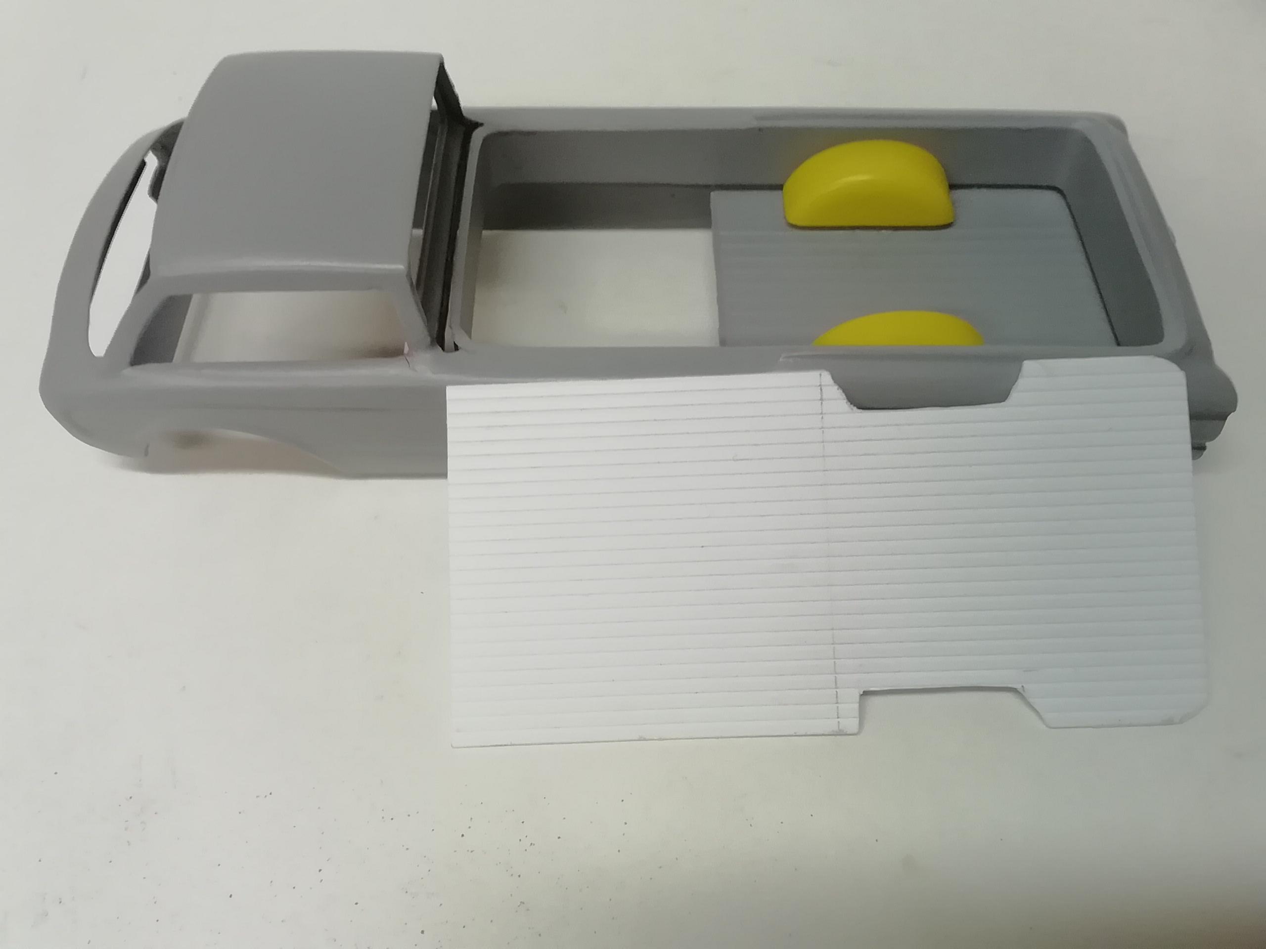
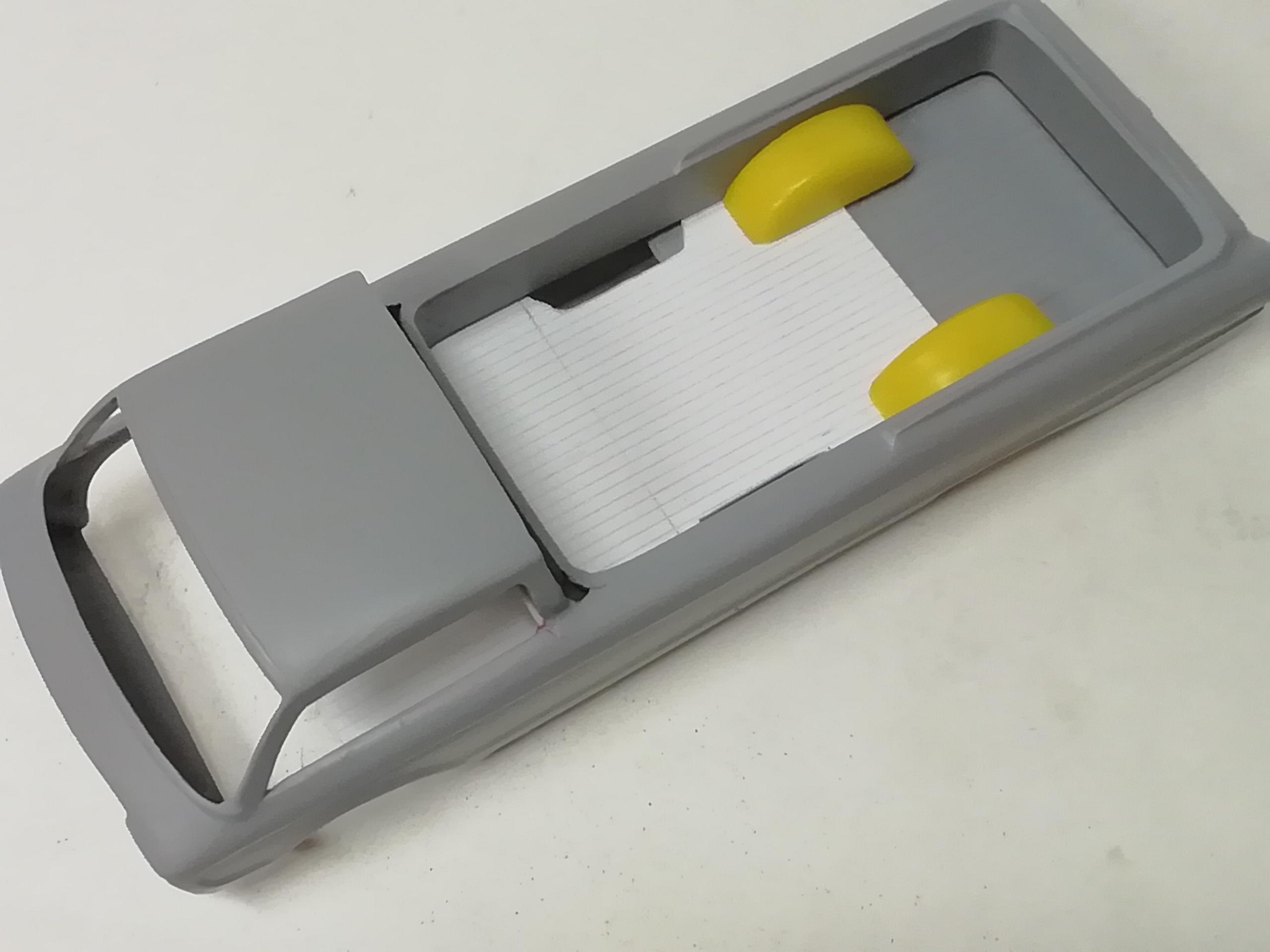
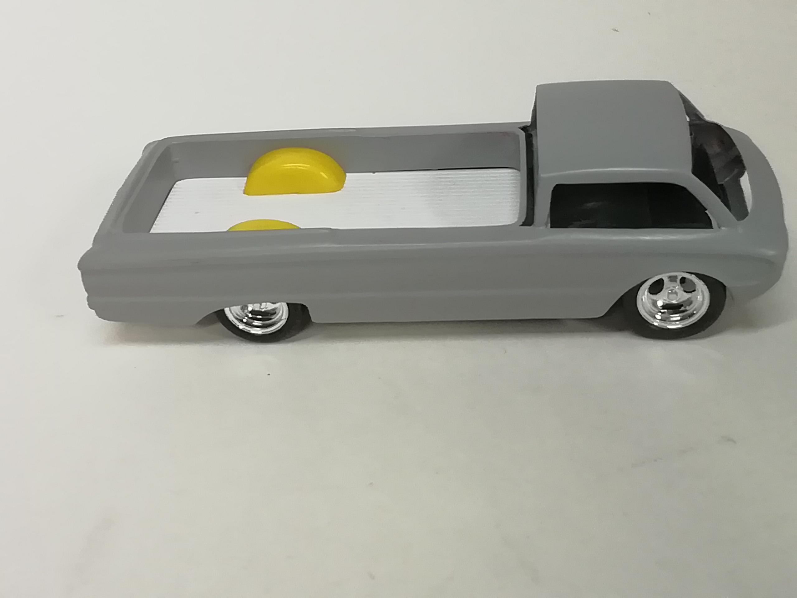
A couple of things. In the shot below, the smooth bed walls are made from a single piece of styrene strip. Once the cab was in it's new position, I went around the new box interior with it, test bending to make sure the bends were in the right place and applying heat to make them permanent, one bend at a time. The ends met in a butt joint with a tiny amount of overlap. I sanded a little at a time between them with a double sided sanding stick, test fitting till only the smallest amount of friction made the rectangle fit snugly in the bed. A small dab of filler and some primer makes the joint invisible. The half bed is the original, ending where it met the cab. The new bed floor was made with evergreen siding styrene sheet. I measured the inside length and width of the opening (before the new wall was installed) for a close fit. I then cut out openings for the new wheel wells, having sawn off the originals. Notice the shadow under the wheel well. The new floor was dry fit on the bed. The wall was then cemented permanently to the sides resting on top of the new floor, and the wheel wells (cut from a Deora glue bomb) attached to the walls, also sitting on the new floor. Nothing was attached to the floor. As shown below, I was then able to slide the floor in place or remove it easily as there will be some cutting to do for engine mounting. Seamless without a whole lot of fuss. Comments and observations welcome
-
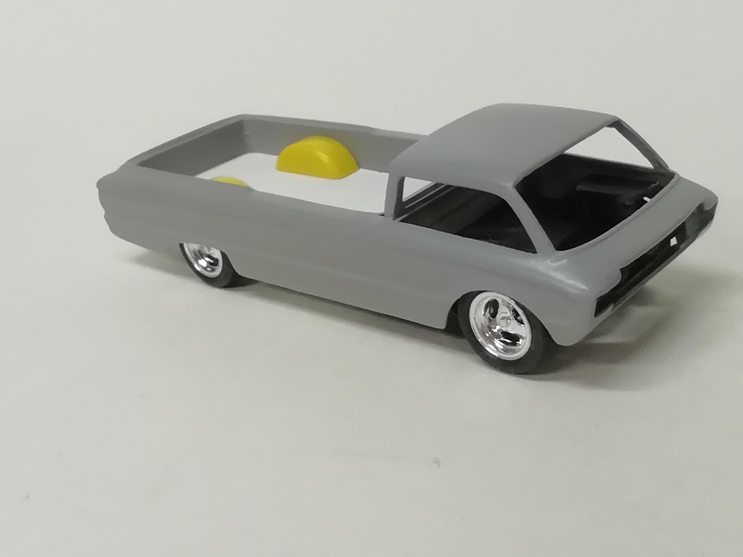
Lol Slusher. Full reveal, the yellow wheel wells are from a partial glue bomb Deora kit I somehow acquired from...somewhere. I'm also using the Deora seats for the Fedora's interior. The Deora was a cabover, the Fedora is a cab forward.
-
Thank you all for the shout outs everyone, much aprecated. Lunajammer, the idea just presented itself with no forethought to where I was going with it so unfortunately no earlier still-in-pieces-pics.
-
Thank you guys, glad you like. Should be a fun build. The Dodge Deora meets the Ford Fedora!
-
Took a bit of head scratchin' to work out the interior due to the wheel wells taking up real estate in the cab but got it sorted out. More photos to follow as assembly progresses. Still working on the body, mostly sweetening up the rough stuff. The grille area is all planned out, so's the engine and placement. I think even the kit wheels look ok for this version. Comments and observations welcome
- 107 replies
-
- 12
-

-
My dad had a 52 Pontiac, overall navy blue, I remember it well. Started my '51 about 6 years ago, maybe now I'll finish it. You've got a lovely finish on yours.
-
Many thanks Craig.
-
It was all my pleasure, Dave. Glad it was of interest.
-
Beautiful job!
-
Here's my rendition of the fuel system as I followed it from a rough diagram. The only lines that come topside are the ones with the tee (#4) to feed the fuel distribution blocks. There are 4 lines per pump. Line 3 goes down on the outside and disappears under the engines. Lines #1 and 2 go down between the engines. ...and that's it. I did this entire build from the beginning on coffincorner2.com, a site focused primarily on showrods, sharing it here part way thru. Comments and observations welcome