Chariots of Fire
-
Posts
2,783 -
Joined
-
Last visited
Content Type
Profiles
Forums
Events
Gallery
Everything posted by Chariots of Fire
-

1944 GMC CCKW
Chariots of Fire replied to Warren D's topic in WIP: Model Trucks: Big Rigs and Heavy Equipment
WB is the distance from center of front axle to center of pivot point of the rea axle pair. If you need the track for front and rear I can get that for you. Also if you use a metric ruler it would convert exactly from inches full size to 1mm being 1" in 1/24 scale. -
1944 GMC CCKW
Chariots of Fire replied to Warren D's topic in WIP: Model Trucks: Big Rigs and Heavy Equipment
Hi, Warren: The wheelbase was either 145" or 164" for the longer version. Found it in TM9-9801 which is the tech manual for the CCKW. As for the decals I made them on my graphics program and then printed them on my ALPS. PM me when you have a minute. -
1944 GMC CCKW
Chariots of Fire replied to Warren D's topic in WIP: Model Trucks: Big Rigs and Heavy Equipment
That looks like a long frame truck. What's the wheelbase? -
2022 Builds Let’s see them
Chariots of Fire replied to Pete68's topic in Model Trucks: Big Rigs and Heavy Equipment
I only did three.
-
Definitely two part molds will be needed, especially for the part on the left and the combination grill bumper assembly at the top. You would need to plug the opening between the grill and bumper with some soft clay or tape the back with some masking tape to keep the mold separated in two parts. If the part in the lower right is straight and flat on the back side you could glue it to a piece of plastic sheet stock, build the mold box around it and then pour the mold material on top of it directly. If you need to keep it as a usable piece use white glue so that you can remove it from the plastic after the mold is made. You've got some work to do, I'm afraid, but hope this helps.
-
I've done similar things to make hinges but instead of putting in a pin on one side I leave both parts open and connect them with a pin that runs clear through from one side to another. After everything is done the way I want it I cut the pin off at appropriate lengths to just fit the two hinge halves. Nice job on your work! They look perfect!
-
You need mold making materials, mold release and casting resin to start. If you can post a photo of what you want to cast perhaps I can offer some suggestions. A two-part mold may be in order.
-
Jeff: If you are interested, I might be able to find an extra DT 466. Let me look around.
-
What do you use for spark plug wiring?
Chariots of Fire replied to customline's topic in Model Building Questions and Answers
Bead wire works well. 0.015 size works best. Comes in a spool in different colors.
-
1944 Diamond T wrecker
Chariots of Fire replied to Chariots of Fire's topic in Model Trucks: Big Rigs and Heavy Equipment
I have two of those and have taken to adding shelves. Will have to add another for this build! -
1944 Diamond T wrecker
Chariots of Fire replied to Chariots of Fire's topic in Model Trucks: Big Rigs and Heavy Equipment
I think if I was to do that I would do so in a diorama setting. But I'm running out of shelf space as it is!☺️ -
1944 Diamond T wrecker
Chariots of Fire replied to Chariots of Fire's topic in Model Trucks: Big Rigs and Heavy Equipment
Thanks for all of your kind comments. Much appreciated. No sitting on the laurels, though. On to the next one! A simple kit build this time. Will keep all posted in the WIP section. -
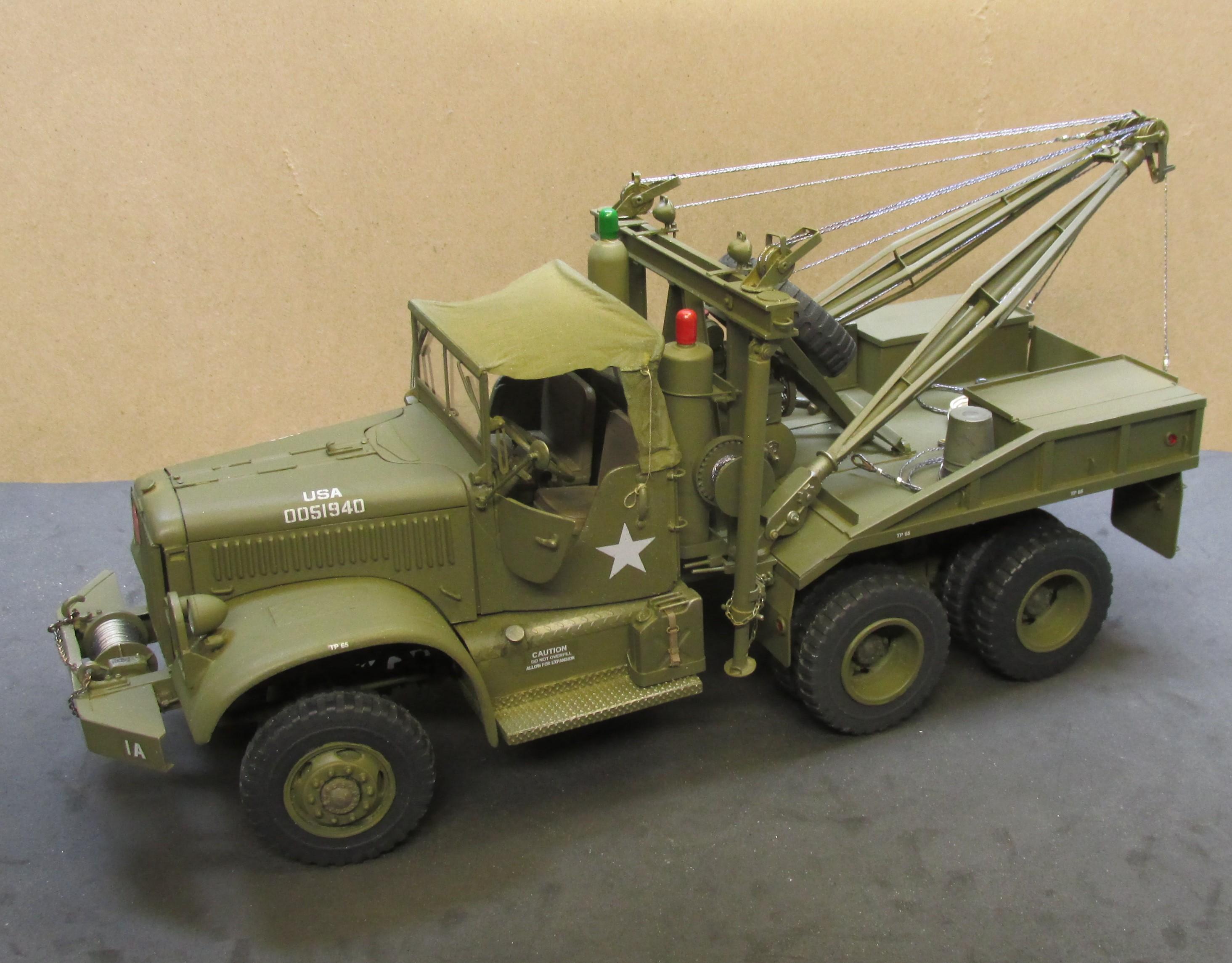
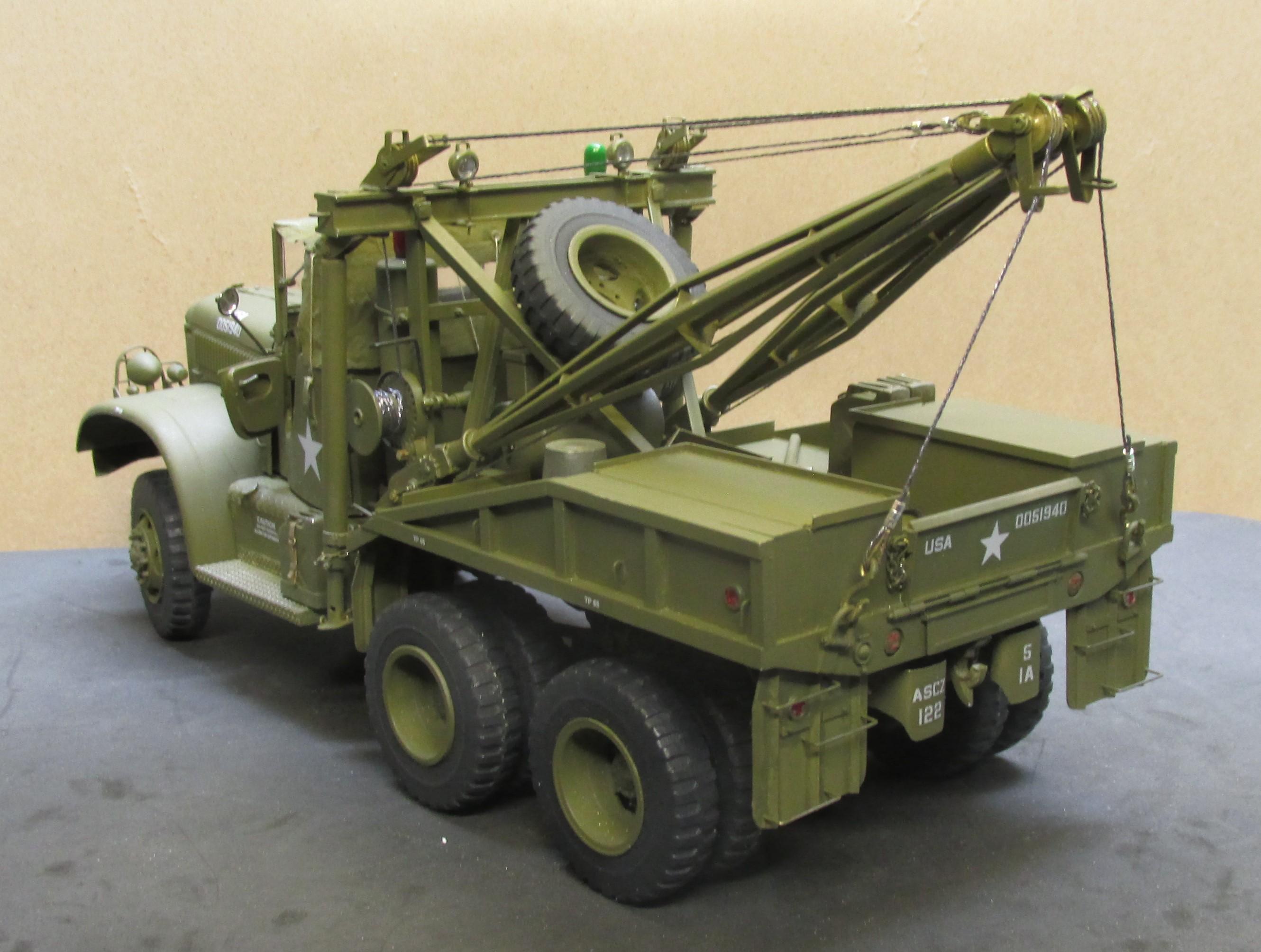
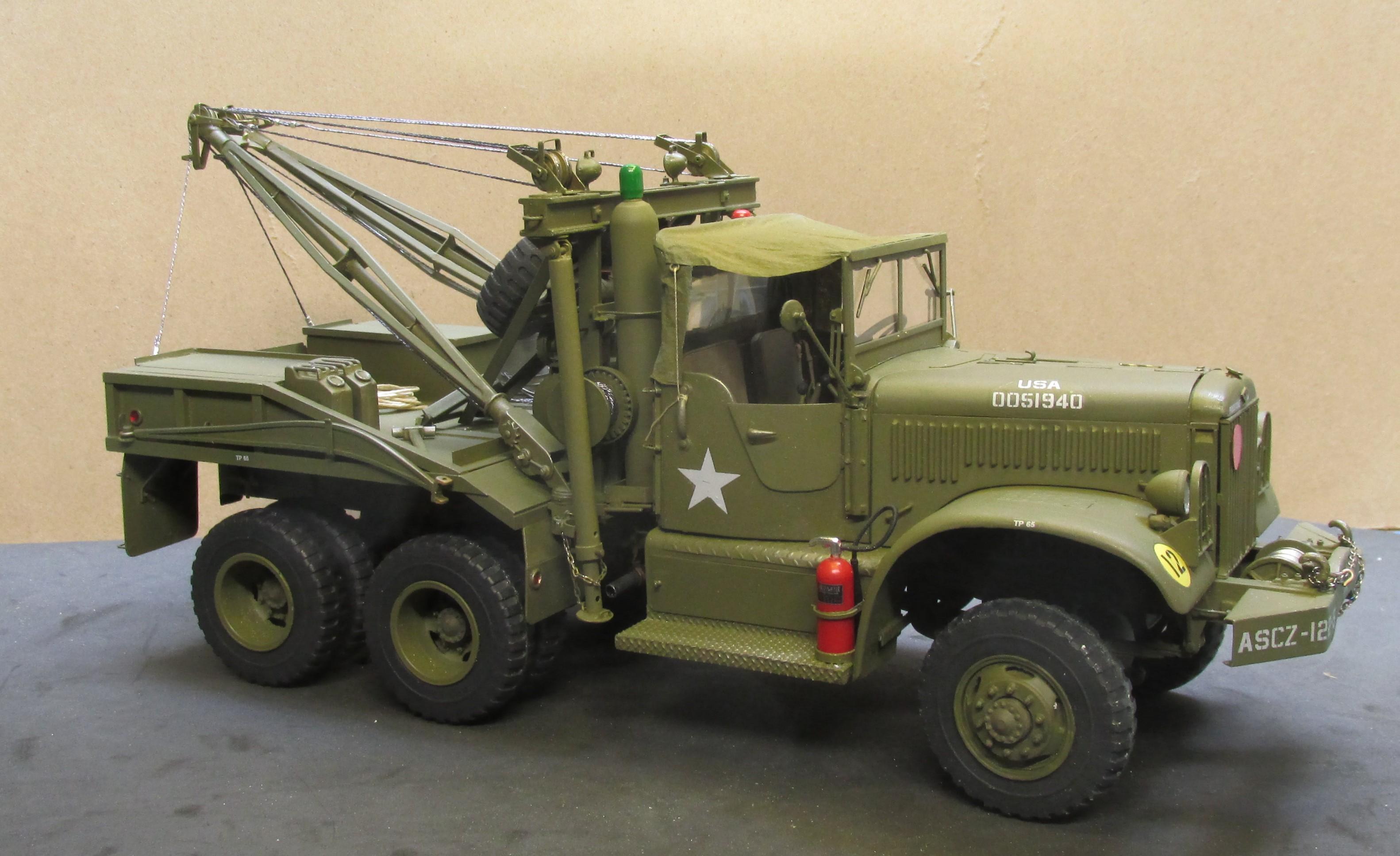
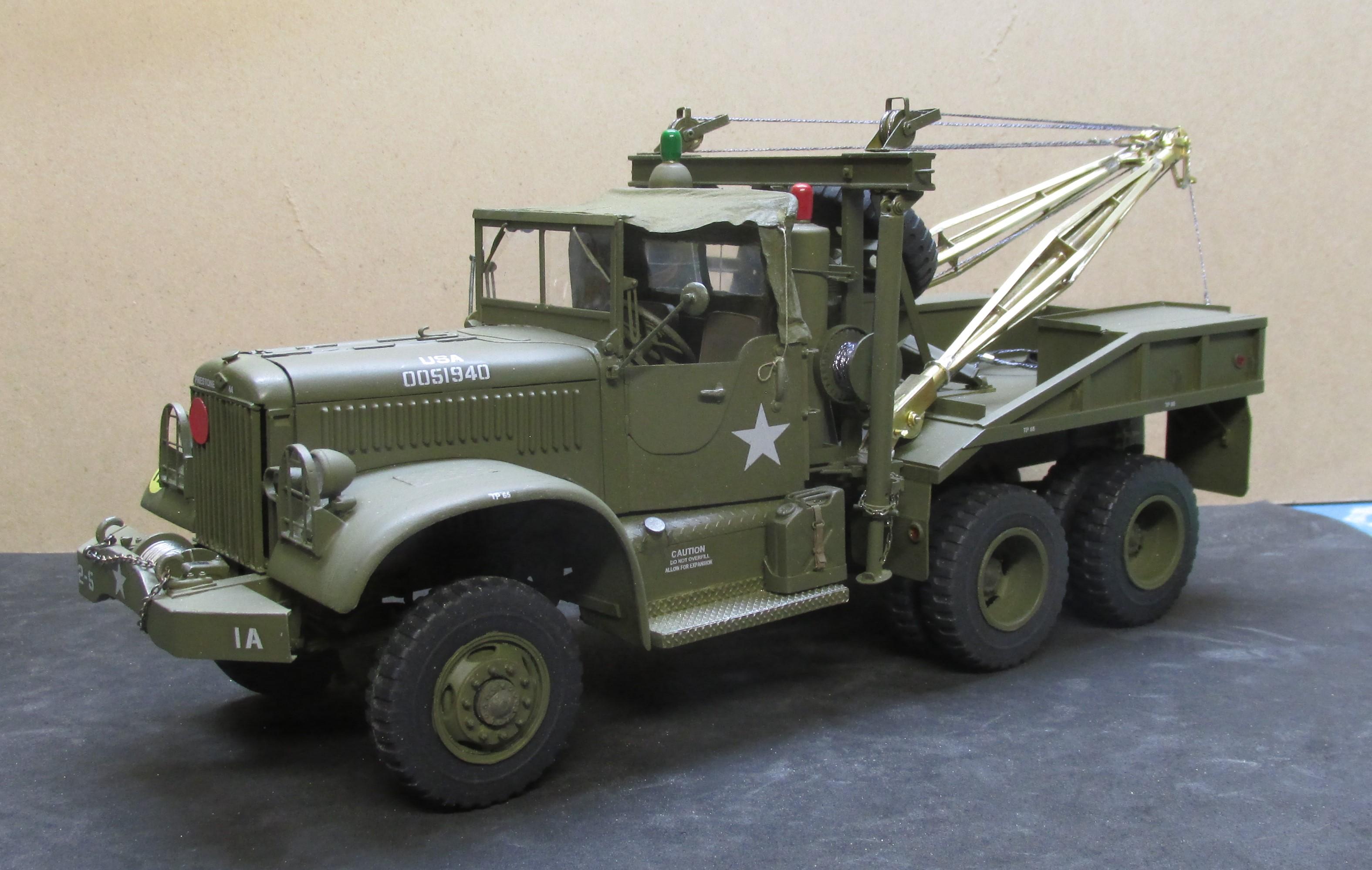
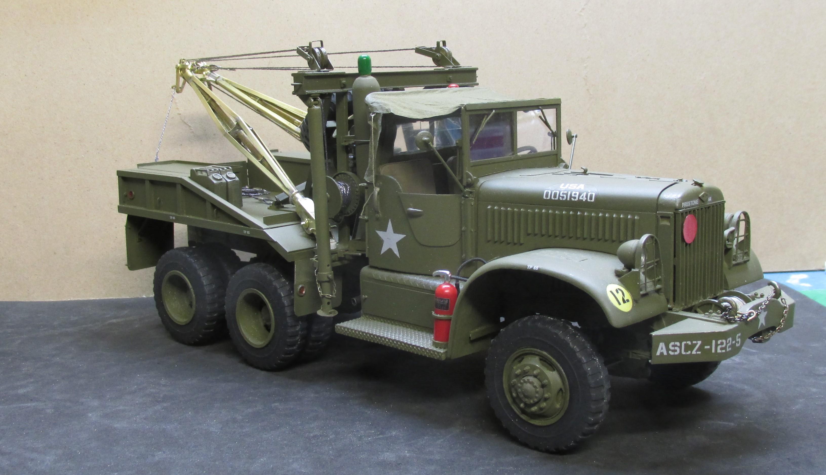
1944 Diamond T wrecker
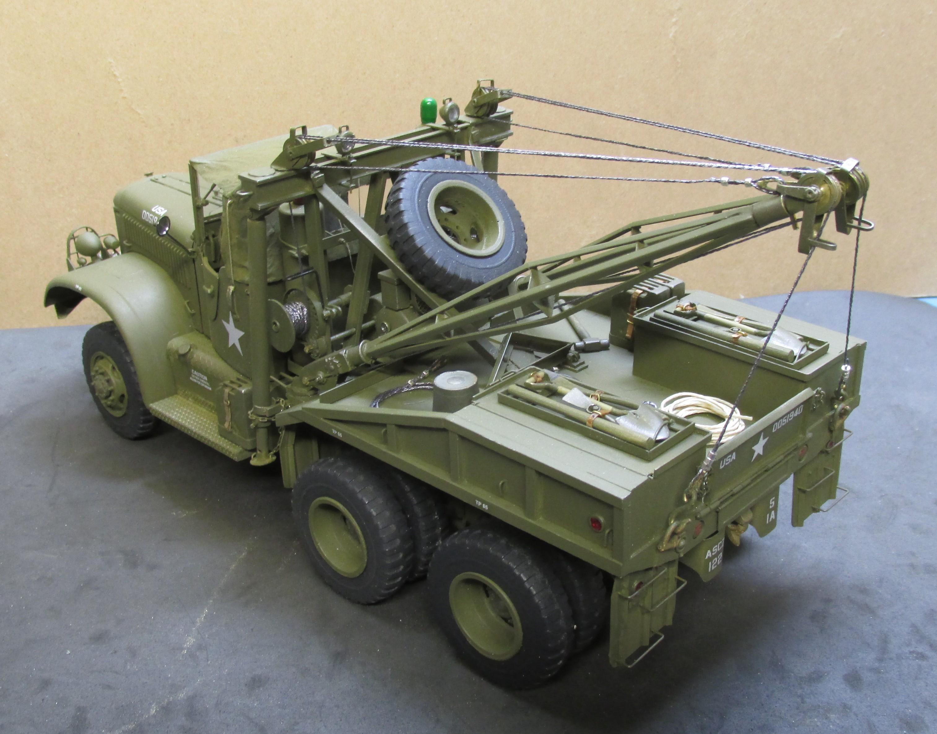
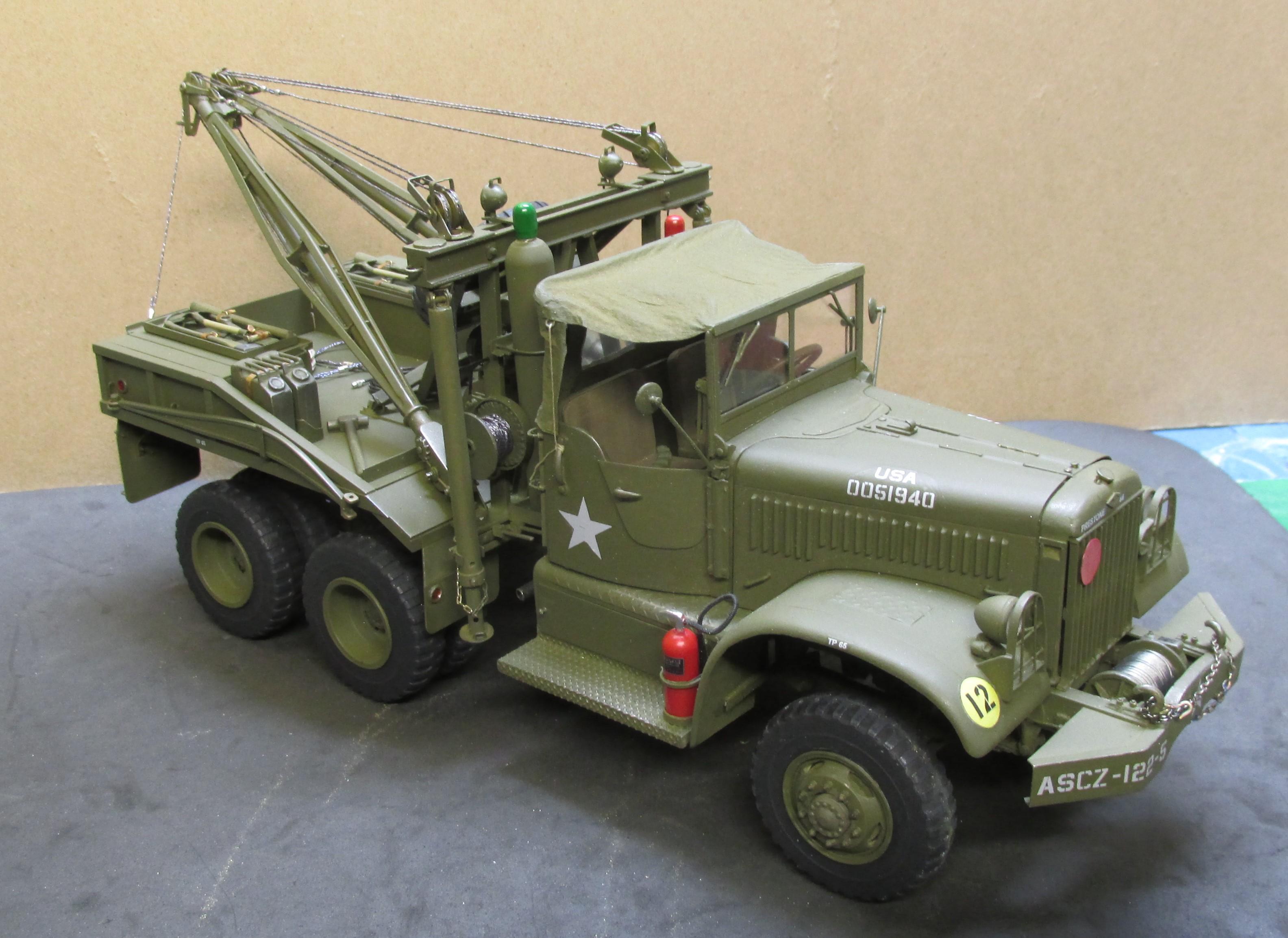
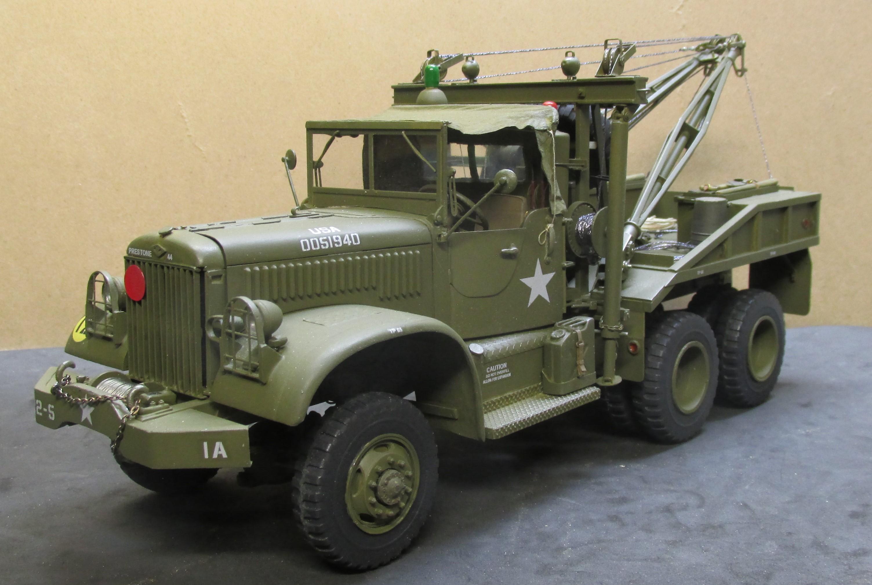
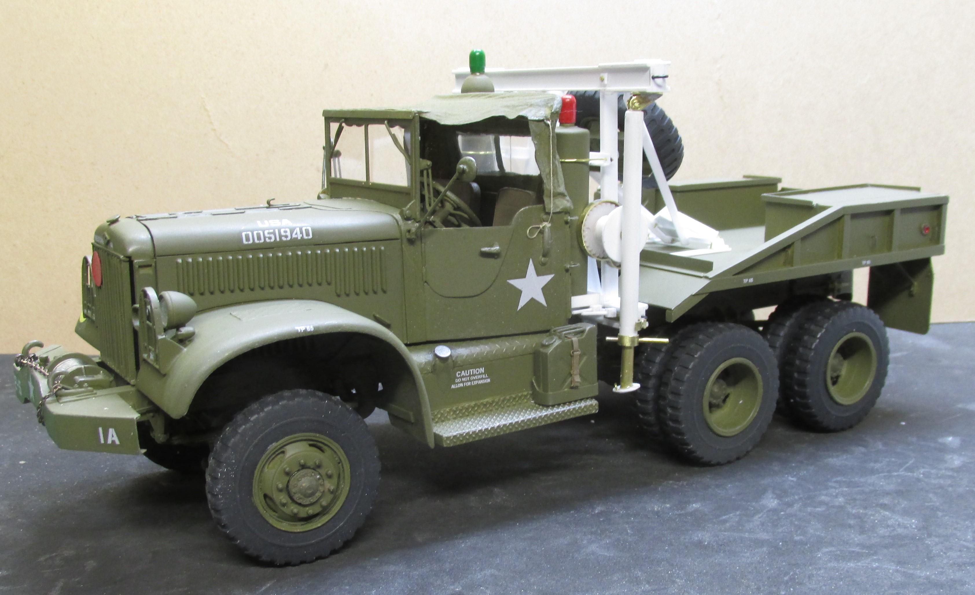
Chariots of Fire posted a topic in Model Trucks: Big Rigs and Heavy Equipment
The Diamond T 4 ton wrecker is now finished. The pioneer kits were added and the GI cans were strapped down. Tools are in the compartments and some tow cables, rope, four stacked buckets and 8 lb sledge are on the deck. Calling the build done.
-
1944 Diamond T 6x6
Chariots of Fire replied to Chariots of Fire's topic in WIP: Model Trucks: Big Rigs and Heavy Equipment
Hey, Brian. Thanks for the comments. The top is made of two ply facial tissue painted in place with 50/50 white glue and water. After if dried I was able to lift it off and paint inside and outside with Tamiya OD. The offsetting color is just the way it came out. Sort of sun bleached if you will. It was made with two parts; the back and sides and then the top. -
1944 Diamond T 6x6
Chariots of Fire replied to Chariots of Fire's topic in WIP: Model Trucks: Big Rigs and Heavy Equipment
The truck is finished. Now it is just a case of putting on the tools and materials. Two pioneer kits need to be made for the tool box lids. Got some "stuff" for the insides as well.
-
Testors Aluminum plate.
Chariots of Fire replied to Mike 1017's topic in Model Building Questions and Answers
I agree. Find another primer. -
Duplicolor paint
Chariots of Fire replied to Steveng's topic in WIP: Model Trucks: Big Rigs and Heavy Equipment
I'm a follower as well. Been using Duplicolor for a long time. I like the fine spray and the hard finish. The more prep you put into the surface before the color coat the better it is. Usually takes more than one coat to cover though. I spray one on, let it dry well, light sand it down and then go to it. -
Oshkosh M 1070
Chariots of Fire replied to Grzegorz's topic in WIP: Model Trucks: Big Rigs and Heavy Equipment
That's some nice work! Scratch building takes modeling in a completely different direction. But if you want something that is not in kit form it's the only way! Will be watching with great interest! -
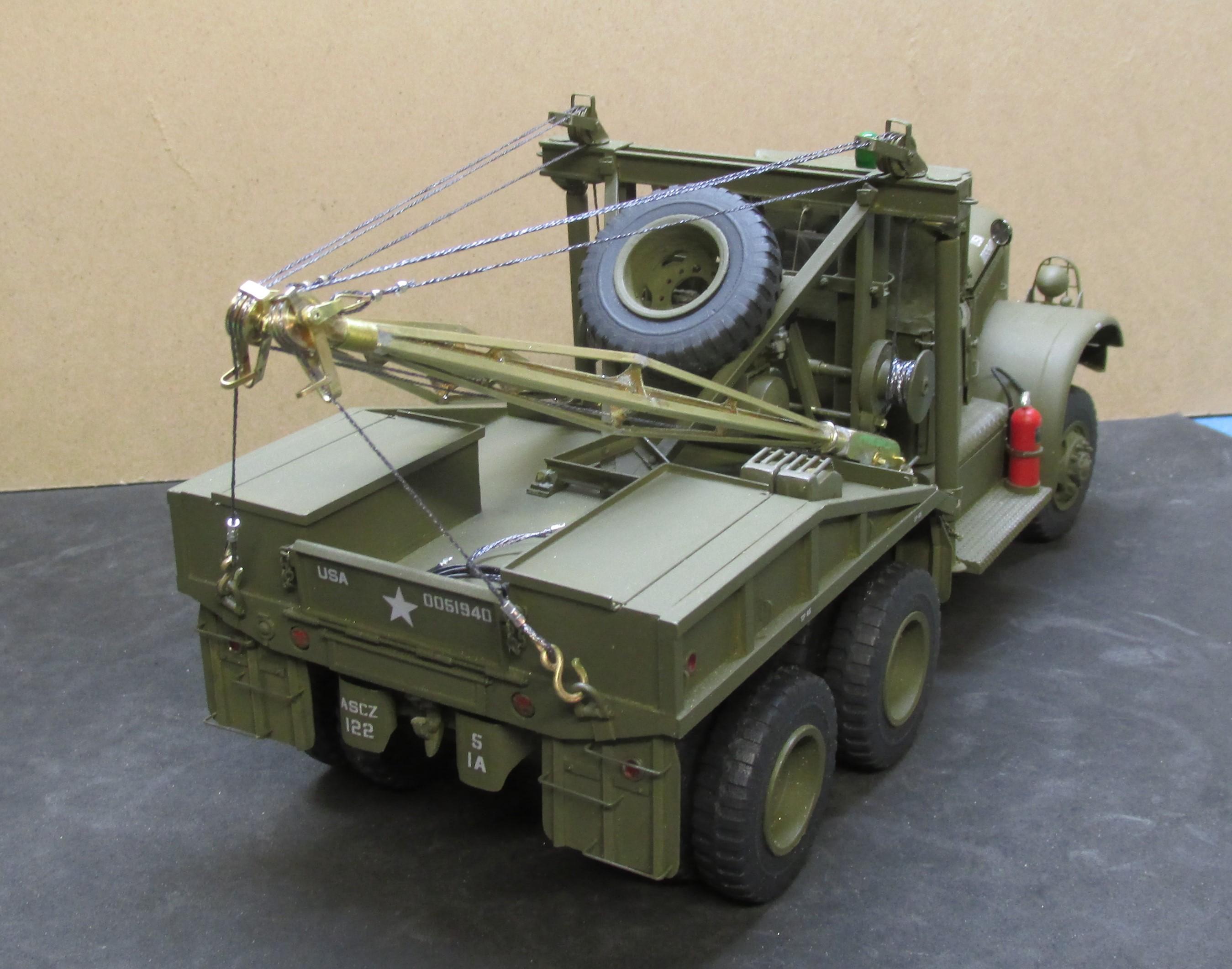
1944 Diamond T 6x6
Chariots of Fire replied to Chariots of Fire's topic in WIP: Model Trucks: Big Rigs and Heavy Equipment
Still making progress a little at a time. Today marked a milestone as both booms are finished and the cables have been strung. They can move the booms up or down and can raise a load independently. Still plenty of work to do but the big stuff is finally done.
-
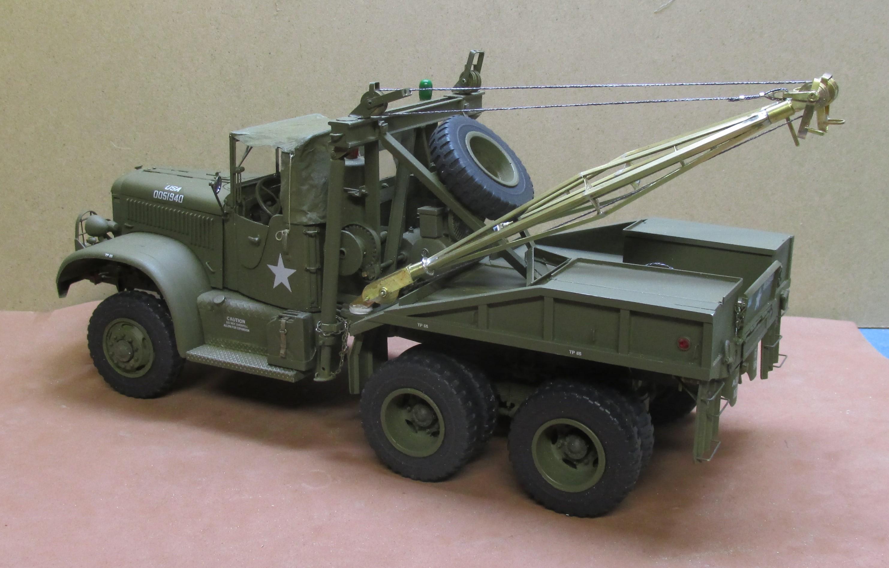
1944 Diamond T 6x6
Chariots of Fire replied to Chariots of Fire's topic in WIP: Model Trucks: Big Rigs and Heavy Equipment
We did, Greg. Quiet but nice. Got the booms done and the double pulleys at the top of each. Was even able to string one side up with the cable that raises it so that it works. Made a crank so that the boom can be raised up and down.
-
1944 Diamond T 6x6
Chariots of Fire replied to Chariots of Fire's topic in WIP: Model Trucks: Big Rigs and Heavy Equipment
Got the booms done and mounted with a temporary cable just to see what it looks like. Not so sure that the booms aren't a bit out of scale but will go with them for now.
-
Any thoughts about widening the fenders? If so I can show how I did my F7. Yours might be an F-6? Those monuments can get heavy!
-
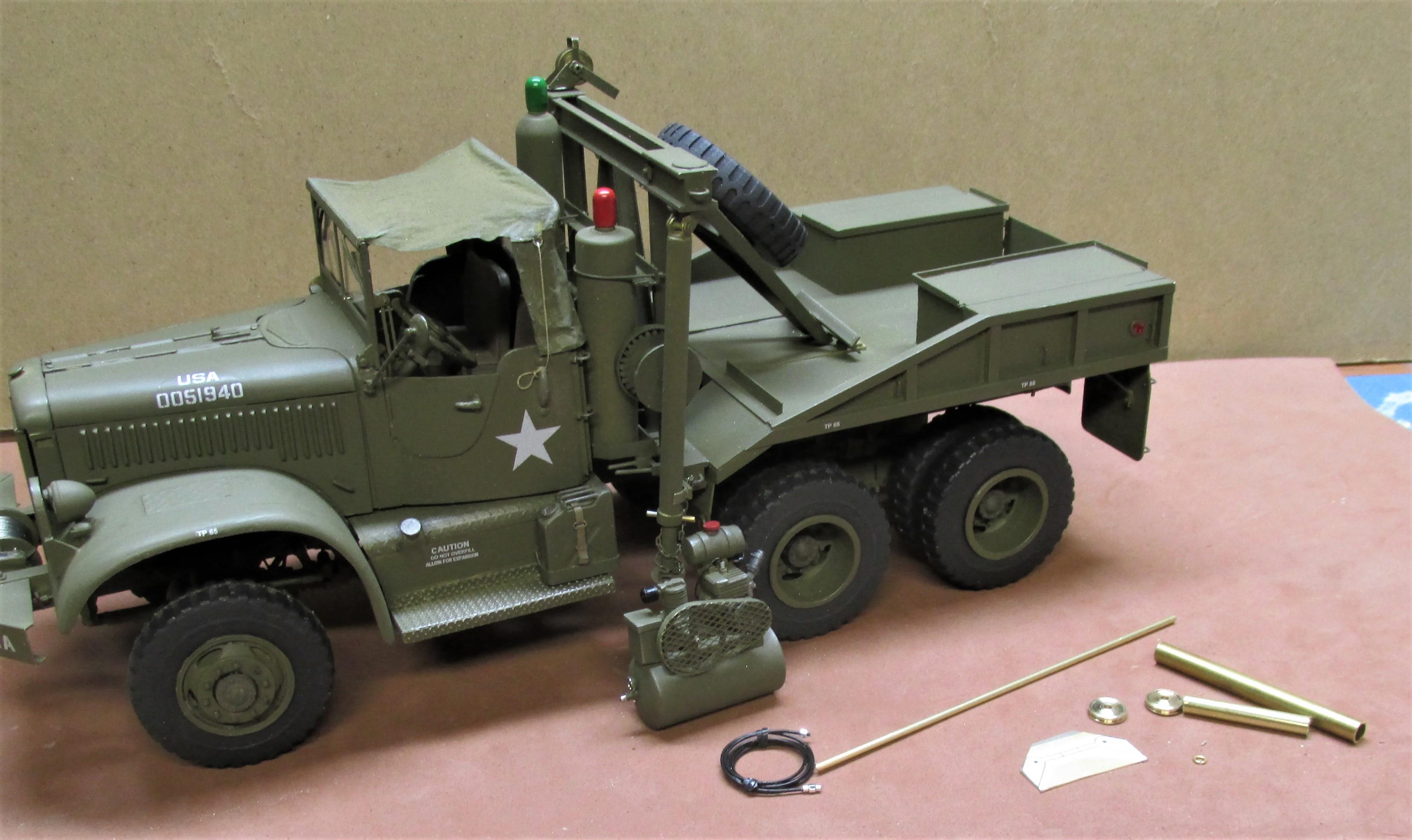
1944 Diamond T 6x6
Chariots of Fire replied to Chariots of Fire's topic in WIP: Model Trucks: Big Rigs and Heavy Equipment
Been doing additional work on the wrecker frame. Winches are installed and awaiting cable. Working on the pulleys for up top. One is done. The other will be made using the brass materials shown. An air compressor and hose are done and go under the wrecker frame and spare tire.
-
1944 Diamond T 6x6
Chariots of Fire replied to Chariots of Fire's topic in WIP: Model Trucks: Big Rigs and Heavy Equipment
Here's a look at the nearly completed frame. I still have the double pulleys to make for the top cross member and the brackets for the booms that attach to the bottom cross member. The rest of the frame work is essentially done.
-
1944 Diamond T 6x6
Chariots of Fire replied to Chariots of Fire's topic in WIP: Model Trucks: Big Rigs and Heavy Equipment
Thanks, Tim. Still plenty to do so there will be more photos to come.