Ace-Garageguy
-
Posts
39,310 -
Joined
-
Last visited
Content Type
Profiles
Forums
Events
Gallery
Everything posted by Ace-Garageguy
-
It's still possible to build a very nice fiberglass replica for reasonable money. If you build it on an IRS VW pan, a replica can out-handle a real one, and if you use a built VW engine putting out more than 130HP, it can out-run a real one.
-
The 356C was built from 1963 through 1965, and all are virtually identical visually (except for tiny variations only a hard-core Porschephile would spot), so this model could be anywhere in there. But what makes this model more special is the 4-cam 2-liter "Carrera" engine. The "bustle" under the rear bumper is the only big giveaway it's a Carrera-engined 356. It was a very expensive car new, around $8000 US (about twice the cost of its 1600cc pushrod-engined brothers), and would be worth in the vicinity of a million bucks today.
-
Really really really REALLY cool, and an inspiration. The 1/24 Monogram Deuce is the best proportioned of all the 1/24-1/25 offerings, but its lack of a separate frame always put me off. Seeing your work here, I think it's time to reconsider this little kit's possibilities.
-
The Porsche 356 series came in four general models, 356 (pre-A), and 356A, B, and C, with sub-variations within the models. (There are also the very early, very rare "Gmund" alloy-bodied cars that look somewhat different, built from 1948-'52) A somewhat loose recognition guide for the standard 356 series follows: 356 pre-A cars through '52 had split windshields, V-eed windshields through '55, narrower and rounded-front hoods, with lower headlights. 1950-1955 The A-series cars were visually similar, but had one-piece smooth-curved windshields. 1955-'59 B-series cars had raised headlights, but retained the round-front A-style hood. 1959-'63 Late B and C-series cars had a somewhat wider and squared nose hood, like this model. C-series cars also went to disc brakes and the 911 wheel bolt pattern, instead of the VW-derived "wide-5" pattern. 1963-'65 More info: https://www.pca.org/news/model-guide-356-the-simple-porsche BEAUTIFUL model, by the way. Best use of quarantine time I've seen to date.
-

\\Hone-O-Drive Unit ?//
Ace-Garageguy replied to 1972coronet's topic in Model Building Questions and Answers
Good question. Is the car you're modeling s'posed to have the unit mounted to the diff, or stand-alone? A quick search leads me to believe it's this one (the text sites Motion Performance), which mounts on its own, with shortened driveshafts to and from it. https://bangshift.com/bangshiftapex/hone-o-drive-overdrive-looks-as-good-as-new/ If that's the correct unit for your build, it looks like a fairly easy scratch-built endeavor. But I am by no means "expert" on these things. EDIT: Yup. Found a ref siting the Model 300, shown above, as the one installed by Baldwin Motion EDIT 2: More info here: http://www.stangerssite.com/honeodrive.html -
Just what it says. Twice I've tried to edit or add new text to older threads, and the photos in the post I'm editing disappear. Not all the photos in the thread, just in the particular post. In the thread below, all the photos in the first post disappeared when I corrected two text typos earlier today.
-
Creating a unfinished looking weld
Ace-Garageguy replied to cobraman's topic in Model Building Questions and Answers
Archer weld bead decals. Similar to their rivets, they're resin castings on a clear carrier, so they provide a real 3D effect. https://archive.armorama.com/review/2764/ -
1956 Ford pickup
Ace-Garageguy replied to Bronzekeg's topic in Model Trucks: Pickups, Vans, SUVs, Light Commercial
Great looking model, built from a kit people love to hate on. Love that color too. Those Testors candy enamels were far from easy to get right, and it looks like you hit the sweet spot. -
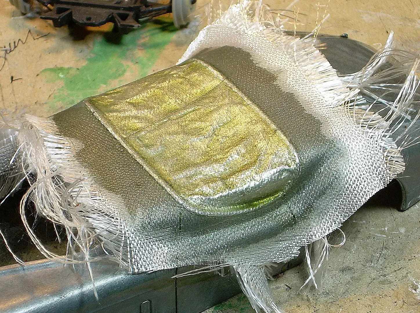
Need convertible top/tarp help
Ace-Garageguy replied to Brandon Miller's topic in Tips, Tricks, and Tutorials
Here's another way to tackle it: I made a tarp from heavy aluminum tape, coated it with mold release, and fiberglassed over it. See the process here:
-
Kinda human nature, ain't it? In the vast majority of cases, anyway. EDIT: And of course it's the basis of "buy low, sell high", and the not-so-golden rule "screw unto the other guy as he would undoubtedly screw unto you".
-
Need convertible top/tarp help
Ace-Garageguy replied to Brandon Miller's topic in Tips, Tricks, and Tutorials
-
I acknowledge that's a large part of the problem, but it's not ALL of the problem. I know of innumerable verifiable instances to prove my point, but as I'm kinda sick and tired of being branded "xenophobe" and worse for stating the truth, I'll refrain from posting examples. But I'll say this much...if some of the things I know to be fact were to happen HERE, people would be running in circles with their hair on fire, screaming "corporate greed" and "corruption" at the top of their lungs.
-
What happened? She lose power and get blown onto the rocks? Sure is beautiful there. I envy you getting to see that every day, though I assume the weather can get pretty intense at times.
-
One culture's "stainless steel" is another culture's pot metal.
-
Remarkable finish for being brush-painted. Nice job.
-
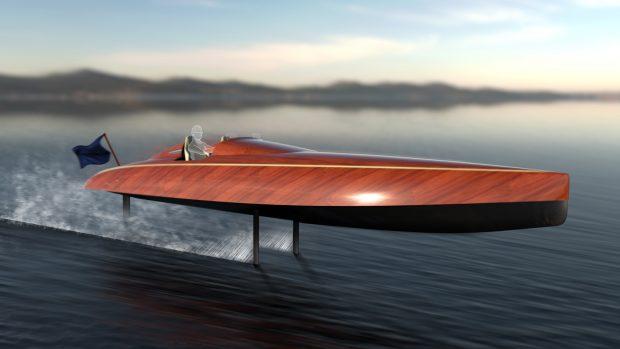
How about a hydrofoil? Or something a little less radical, by McLaren designer Frank Stephenson?
-
Nice trio showing off the possibilities with this kit.
-
I'll usually use a small half-round file to remove something like that, followed by 400 grit paper on the worked area prior to primer. Trying to remove those with just sandpaper...the paper tends to ride over the high spots and cut plastic down adjacent to them, making a wave. File it flat first, you don't get that particular problem.
-
Full article here: https://ahrf.com/don-waite/ More here: https://www.jalopyjournal.com/?p=28606
-
Autoquiz - #557 - Finished
Ace-Garageguy replied to carsntrucks4you's topic in Real or Model? / Auto ID Quiz
-
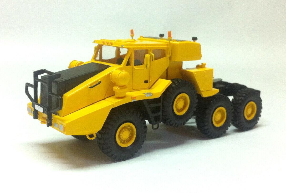
Truckquiz #10 - Finished
Ace-Garageguy replied to carsntrucks4you's topic in Real or Model? / Auto ID Quiz
I snoozed, I lose. I actually knew that one from a model railroad search several years back that took me to Michael's very own Fotki page about that exact vehicle. https://public.fotki.com/carsntrucks4you/reference-pictures-1/reference_pictures-3/kfm_tb_600_heavy/kfm600_4.html#media I recognized it immediately, had the pix and links saved, but was way too slow on the trigger posting here. Oh well. EDIT: HO scale version...
-
-
Returning Sprues
Ace-Garageguy replied to Jim B's topic in General Automotive Talk (Trucks and Cars)
Small scale styrene injection molding, desktop-size, is possible as I write this. I posted links and vids some time ago. Recycled sprue would be ideal in that application...make your own styrene parts. The dies can be 3D printed, but the downside is it would require many multiples of any part made to be worth the time and effort involved. How many '37 Caddy hubcaps can you really use? -
Returning Sprues
Ace-Garageguy replied to Jim B's topic in General Automotive Talk (Trucks and Cars)
That's most likely a patentable idea. You should build a prototype, patent it, then see if you can sell it to a model company...or somebody. -
Returning Sprues
Ace-Garageguy replied to Jim B's topic in General Automotive Talk (Trucks and Cars)
A good idea at first thought, as polystyrene is relatively easy to recycle, though not necessarily back to its original application. Because of the likelihood of contamination, and mixed colors and formulations, it's doubtful recycled styrene would end up as kits again. Also, there has to be the incentive to do it, and that always involves money. An employee would have to run the show, manage finding a suitable recycler, shipping the stuff, etc. And unfortunately, recycling plastics is more complex than many assume. Quoting below from a solid source: "High Impact PolyStyrene (HIPS) is a recyclable material For a world that needs to reduce its plastic waste, using a 100% recyclable plastic packaging solution, such as HIPS, is not a problem, especially for organizations that want to reduce their carbon footprint. Because High Impact Polystyrene is a thermoplastic that can be easily formed using heat, it can be recycled in a wide variety of applications. Not only does this show how flexible the material is, but it can be useful beyond its original purpose. However, High Impact PolyStyrene (HIPS) and other recyclable forms of polystyrene are often not acceptable in recycling plants. In the UK, for example, only 30% of the UK population has access to factories that allow the recycling of HIPS products such as glasses and disposable tableware. Unfortunately, this is part of a global problem where only 14% of the world’s plastic packaging is recycled annually. Because most recycling plants cannot sort and reprocess up to 50 different types of plastics. This wide variety means that plastic recycling is a complex task, especially when compared to how other materials are recycled.