BK9300
-
Posts
1,993 -
Joined
-
Last visited
Content Type
Profiles
Forums
Events
Gallery
Everything posted by BK9300
-

72 jimmy and 72 c10
BK9300 replied to 53gmc's topic in WIP: Model Trucks: Pickups, Vans, SUVs, Light Commercial
Nice finish to your pickup - the V6 has great detail and I like your photo setup! Where did you get your 'overhead' light? -
1/32 Freightliner cabover
BK9300 replied to Rockford's topic in WIP: Model Trucks: Big Rigs and Heavy Equipment
Fine looking truck, Steve! - good compromise with the tape and the rest of the decaling looks great, too. (good idea with the aluminum tape - I've seen some here in the hardware store that may be very similar - thin and crazy sticky) -
Mid 60s Peterbilt Unilite COE
BK9300 replied to RoninUtah's topic in WIP: Model Trucks: Big Rigs and Heavy Equipment
Great idea using the straw for your exhaust indent in the cab. I don’t much like body work, so good on you for taking on a lot of it! -
My 1st Big Rig "Blue Collar"
BK9300 replied to James2's topic in WIP: Model Trucks: Big Rigs and Heavy Equipment
Going to be an impressive looking truck - like the colour of your inspiration truck. -
I like your interior work - the kit’s molded dash detail looks simple, but your detail painting sure enhances it! What have you used for your gauge ‘lens covers’ ?
-
Cyber punk ‘88 Dodge Daytona/Mercedes C9 kit bash
BK9300 replied to Steve H's topic in WIP: Model Cars
Great progress, Steve! I don't have the imagination for a build like this, but I appreciate following along with this quality build -
Pete 352 day cab
BK9300 replied to Jürgen M.'s topic in WIP: Model Trucks: Big Rigs and Heavy Equipment
Another interesting build finished in fine fashion - great work, Jurgen! -
You produce such well detailed, clean builds - awesome!
-
Crazy amount of detail work - just a beautiful, well executed build!
-
Once again, another great project completed, Jurgen! looking forward to your next project.
-
Volvo VNL860 - new 3D print
BK9300 replied to Bren's topic in Truck Aftermarket / Resin / 3D Printed
More like well stated opinions than pontification! All good thoughts about printing and its place in the hobby. For now, l need to settle for locally outsourcing the printing of my limited need for 3d parts as a first step, then who knows. Thanks, also, for your thoughts on my build. -
Volvo VNL860 - new 3D print
BK9300 replied to Bren's topic in Truck Aftermarket / Resin / 3D Printed
I appreciate all the good info - not sure if I’ll ever find my way into resin printing, but I can sure see where a build could be improved by being able to print your own parts. Scratch building working for me at the moment but some parts are just too small to make! Thanks again. -
Volvo VNL860 - new 3D print
BK9300 replied to Bren's topic in Truck Aftermarket / Resin / 3D Printed
I often read about shrinkage and warping occurring during the post printing, curing process. Have you had any issues related to that in your prints? -
New 2024 Peterbilt 579 Hi-roof sleeper
BK9300 replied to RoninUtah's topic in Model Trucks: Big Rigs and Heavy Equipment
Good looking truck, Ron! Seems 3d printing will produce new build opportunities that just aren’t being offered by traditional kit manufacturers. -
The bane of my existence! Pete 353
BK9300 replied to Bren's topic in WIP: Model Trucks: Big Rigs and Heavy Equipment
The hood may be giving you grief, but you sure nailed the rest of it! Tremendous detailing! -
Roanoke Railhouse Beer GMC General
BK9300 replied to Gary Chastain's topic in WIP: Model Trucks: Big Rigs and Heavy Equipment
In my opinion, with your addition of the strengthening rib, and the fact that you intend to put three hinges on each door, the weight of the doors shouldn't stress the hinges enough to make them fail. I think where the hinge plate attaches to the hinge barrel will be the weakest point - even so, with three hinges, each door should work well. -
Pete 352 day cab
BK9300 replied to Jürgen M.'s topic in WIP: Model Trucks: Big Rigs and Heavy Equipment
Procrastination doesn't seem to have any place in your world! A 'problem encountered' very quickly turns into a 'problem solved' - great progress! -
Truly masterful work - a pleasure to see it come all that way, from a basic kit, to its final, grand completion - amazing work!
-
Western Star 4900 FA plow truck
BK9300 replied to BK9300's topic in WIP: Model Trucks: Big Rigs and Heavy Equipment
Thanks, Charles- I was thinking about that too, because there should be some bits of sand left in the conveyor from the calibration process! -
The Same but “ a little “ Different
BK9300 replied to Biggu's topic in WIP: Model Trucks: Big Rigs and Heavy Equipment
Geez, Jeff, had an off day from the forum and you added a page to your thread - I missed all the work you’ve added since you started the plumbing on Page 4 - looking really good! -
Western Star 4900 FA plow truck
BK9300 replied to BK9300's topic in WIP: Model Trucks: Big Rigs and Heavy Equipment
Here's hoping - thanks! -
Oh, noooooo... They're multiplying! '90 MUSTANG LX 5.0 - The SILVER FOX
BK9300 replied to mrm's topic in WIP: Model Cars
Catching up on your build - great detail work on your engine and engine compartment - adds so much! -
Cyber punk ‘88 Dodge Daytona/Mercedes C9 kit bash
BK9300 replied to Steve H's topic in WIP: Model Cars
It's very impressive when your scale modifications look like they came out of a real life custom fab shop! -
Western Star 4900 FA plow truck
BK9300 replied to BK9300's topic in WIP: Model Trucks: Big Rigs and Heavy Equipment
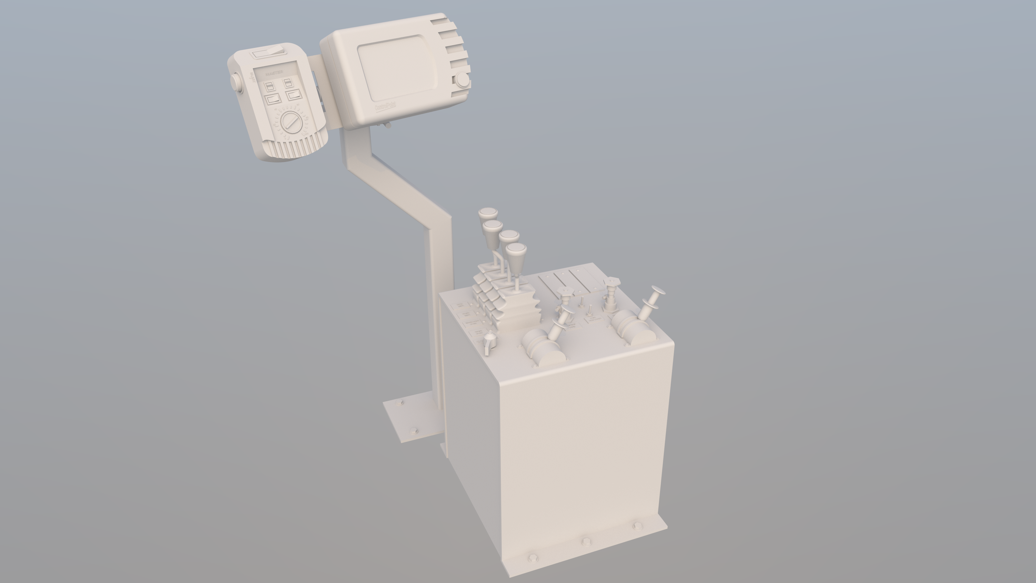
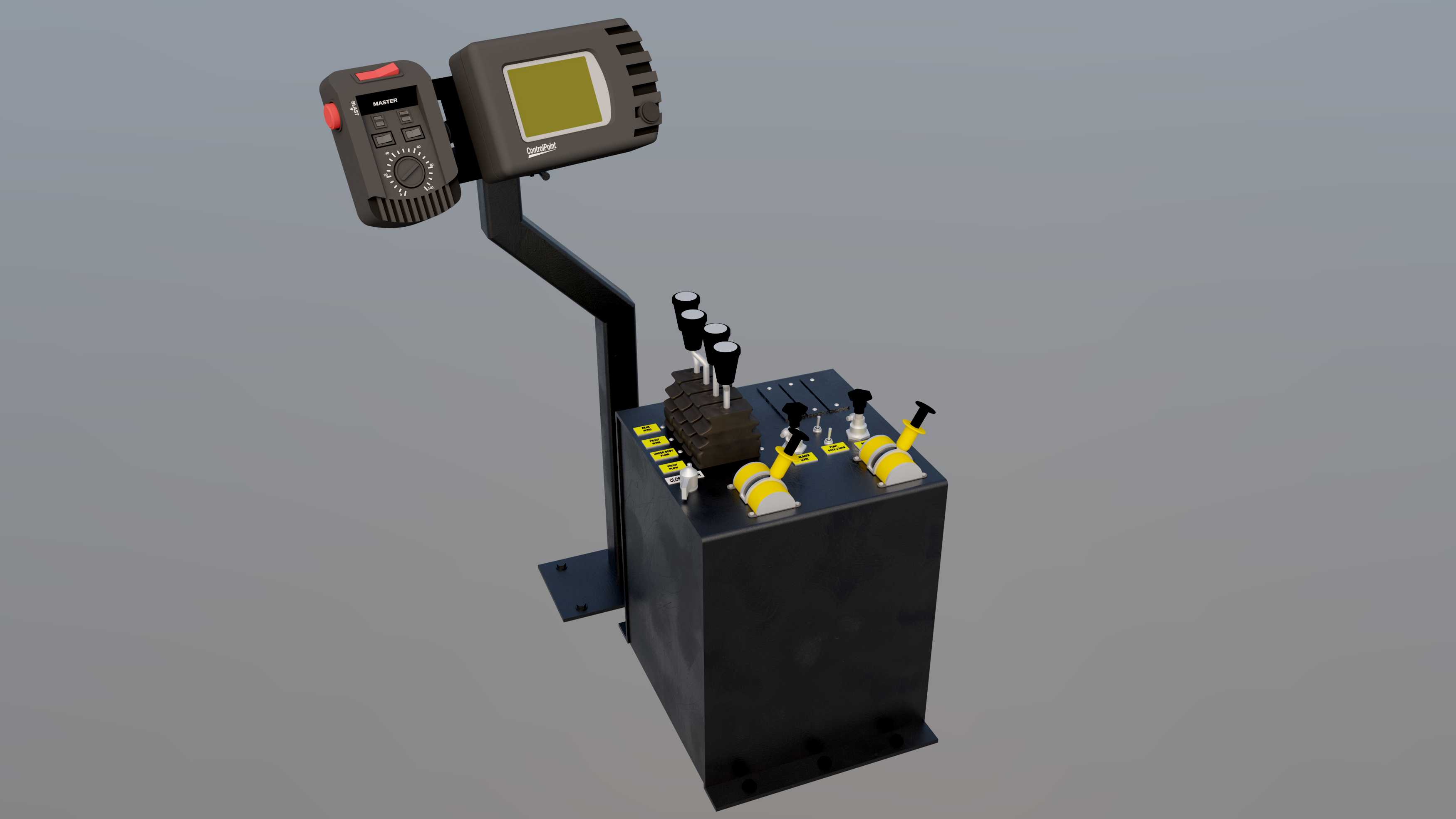
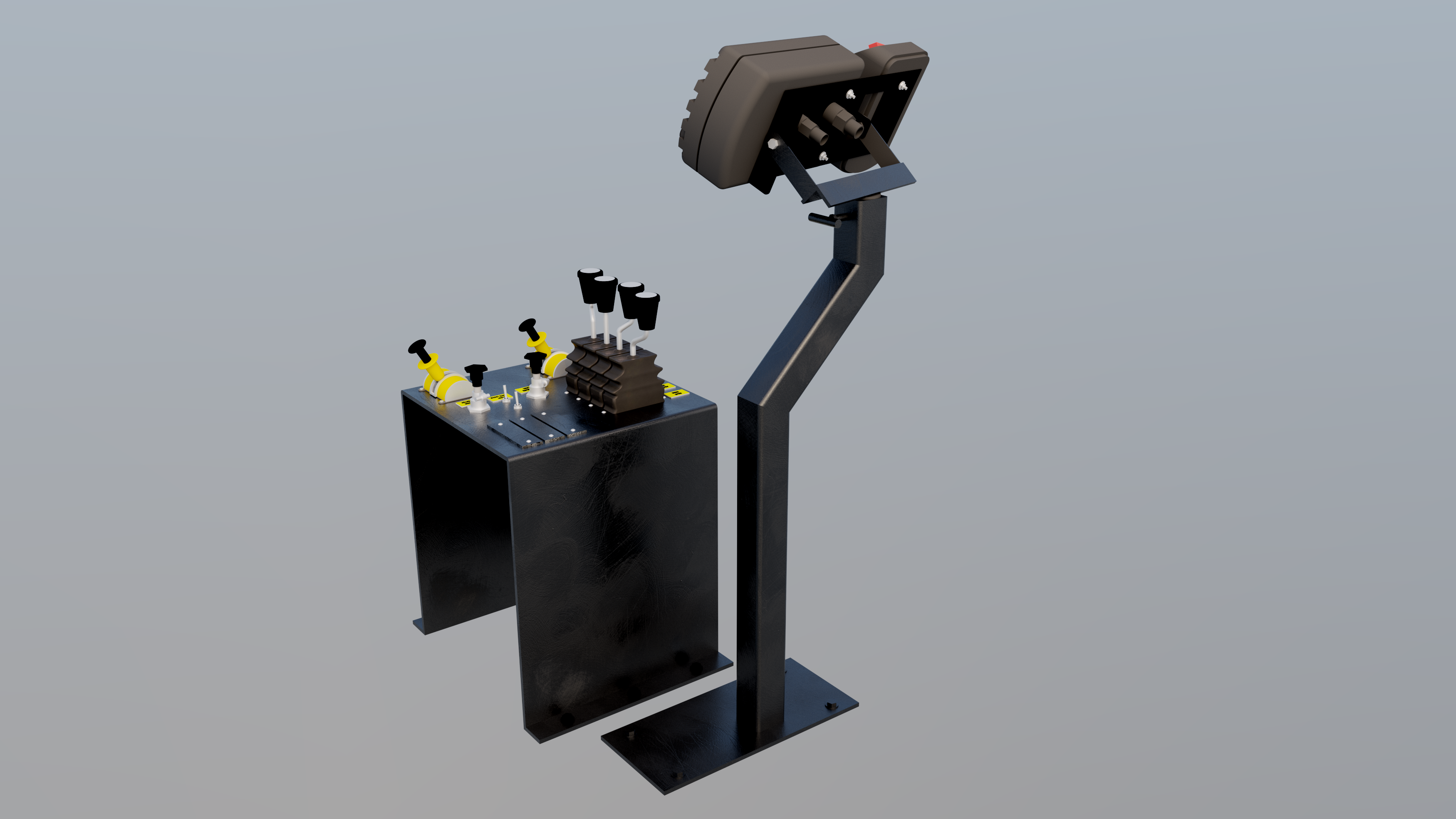
So, things are well enough for me to have spent some time in my Sketchup program the past couple days, building the 3D control console file. I've finished it to the degree that it makes no sense to put in more details, as a 1/24 version just won't show it, or even be printable. In fact, until I can talk with someone who knows what's achievable, I'm not certain the detail I do have is printable. The scale size of the metal 'box' that the controls are mounted on is 13 mm x 13mm x 16mm and the overall height from the model's floor to the top of the display monitor plus its mast, is slightly less than 1.5 inches (see an earlier post for some pics of this console in a real truck). I guess I'll find out this week what printed detail can be achieved when I talk to the university club. In the meantime, a few renders of the model control panel! This render was done with no colours or textures rendered, just a 'clay model' as I've heard it called. Same view with colours and rubber, plastic and metal textures applied to the model - if you zoom in on pic you can see lots of little detail that likely won't be able to be printed. Passenger's side view of console and monitor - a good deal of wiring comes out the back of the monitor and runs down and into the back of the metal console box - have to figure something out for that too. Its all going to be very tiny, if it can be printed anywhere near what I would like it to turn out to be. And if it does turn out ok, its going to be very difficult to detail. . .another problem to deal with! Take care.
-
Western Star 4900 FA plow truck
BK9300 replied to BK9300's topic in WIP: Model Trucks: Big Rigs and Heavy Equipment
Thanks, Steve, and likewise back at you!