Mr. Metallic
-
Posts
2,783 -
Joined
-
Last visited
Content Type
Profiles
Forums
Events
Gallery
Everything posted by Mr. Metallic
-
AMT 1963 Impala - Advanced Custom Version
Mr. Metallic replied to Impalow's topic in WIP: Model Cars
I am definitely on board with this dragster idea. I'm sure your creative mind will come up with something spectacular. Not to hijack, so feel free to ignore, but any idea where these wheels are from? (not sure if Todd is a member here) Are they the custom wheels from the old Revell 56 Chevy?
-
Paint Strippers - What to Use?
Mr. Metallic replied to pbj59's topic in Model Building Questions and Answers
I recently had to replace one of my strip tanks. As I started searching i stumbled upon these at WalMart. If you're like me you have your paint striping tanks at your bench and have to carry them to the nearest sink for cleanup. This container has a built in handle for easy transport. And they're a good size, big enough to fit a Buick Riv easily inside. -
"Simple" Revell 30 Model A Coupe. finished 4/11/2022
Mr. Metallic replied to Mr. Metallic's topic in WIP: Model Cars
Tying up loose ends Just a few items remaining to be addressed before we're ready to move on to paint. First, a change to the rear suspension. This change is completely optional and comes down to personal preference. The first pair of suspension arms I made for the rear would work, but I wasn't sold on how they looked. Mounting so far out on the end of the axle, and attaching to the outside of the frame is fine, but not the most aesthetically pleasing. Especially since their mounting point interrupts one of the signature design elements of the 32 Ford frame, the graceful sweep stamped in the side. In the effort to keep the build in the realm of "simple" I decided to modify another item included in the kit to make it more traditional in appearance, the rear suspension arms for the later era engineered coil-sprung suspension. In the top of the pic is the kit supplied part. Depending on which rear axle you chose you may need to enlarge the U shaped area on the bracket as I did here to fit my axle choice. Then go ahead and remove the upper bar and modify the bracket further to reduce it's size until you are happy with the shape. Finally, insert a pin through the former location of the forward mounting bolt and ink mark the point on the frame where you will drill the receiver hole. Now you can see the new arms in their final location. A little more cleanup needs to happen to the arms, but you can see the cleaner and more prototypical arm setup. Now lets make a couple simple shocks to finish up the rear. If you can find something in your parts box or kit stash that fits, by all means use those. But this design of shock allows you to customize the fit for whatever ride height you have ended up with because the length of the piston can be adjusted. The size of the parts is up to you, just as long as the finished items match each other. I cut a couple pieces of tubing for the shock casing, and then a couple lengths of styrene rod that would fit inside the case piece. Take a short length of the same tubing and drill a hole in the side very near the end, the same size as the rod you're using for the piston. Glue a short length of the rod into the hole, and then cut the tubing off. Proceed to then cut 2 more approximately 1mm pieces of tubing and then attach them to the top of the casing pieces. After all your cutting and gluing is done insert your new piston into the end of the case and you have your adjustable shock. Pin the shock to the axle at your desired spot. Just a tip, you can make the shocks out of aluminum or brass instead of plastic if you choose. Lets move on to the floor pan and frame. Now that's you're done with all the frame mods we can permanently attach the floor pan to the frame. In the pic you can see the finished frame on top. This is achieved by removing the section marked in red on the white floor pan. The one in the pic doesn't have any of the mods we completed earlier in the build. Glue the two parts of the floor pan to the frame. With that done, lets take care of the final component of the build, the exhaust. In theory you could just run with the side pipes, but that hot rod is just asking to get pulled over and give a citation for excessive noise. You can use the main exhaust pipe/muffler, but we need to move it more towards the center to avoid the suspension arm and snake through the tight space between the axle/spring (it's not as tight as it looks) Remove the plastic mounting pins on the exhaust and replace with metal pins (before and after in the bottom of the pic). Because we moved the exhaust inboard of the kit intended location we are going to have to fabricate our own pipe to join the header to the muffler. Using the kit supplied pipe as a pattern bend a new piece out of solid core plumbers solder, making the upper part longer to meet the muffler. A roll of solder can be purchased for about 10 dollars and will provide several cars worth of full exhausts. Use a pair of plyers to bend the solder to the desired shape and then trim the ends to fit. You may find it helpful to file the end that meets the header to a point so it slides into the hole in the bottom of the header piece (far right in pic) And here you can see the complete exhaust layout. I am planning to use the kit supplied metal tips for the end. And now, fabrication is complete and you can move on to prepping everything for paint. -
To get the front end a little lower you can remove material from inside the crossmember. Since the Revell Model A axle has the spring mounted on top of the axle it's hard to get it much lower without a z in the frame, or moving the spring. I know the z is probably out of the question for this iconic car, and moving the spring behind the axle will probably drop it too much? Here is the mod I performed for my "Simple" Model A else where on this board.
-
Classy looking roadster you have there. The SCoT-style blower setup is from the 60's vintage AMT 57 Chevy kit
-
Nice squeaky clean customizing. I really like the subtle scallops. Well done
-
The body was only tooled up in the 90's, so it surprises me that the mold has deteriorated that much. The rest of the kit is the 55 Nomad tooled in the 60's, so you're correct that some of the kit is old. Just thinking about it now though, i guess the 90's are 30 years ago, so could be considered old ?
-
Those are a great looking wheel. Glad i finally have a name to go with the ones on my Son of Ford build. But these AMT ones are cool because they have a bit more detail on the rim and are a different offset than the Monogram parts.
-
I don't believe I've ever seen those 4 spoke Rader ribbed wheels before. Wild
-
"Simple" Revell 30 Model A Coupe. finished 4/11/2022
Mr. Metallic replied to Mr. Metallic's topic in WIP: Model Cars
YESSSS!!!! This is exactly why I've tried to be as descriptive as possible in this WIP. I've been helped along the way by so many builders over the years that I wanted to try to do help someone else. Seeing someone actually use what I described is very rewarding. glad it worked out for you, they look great! BTW, didn't know they ever offered the 41 Lincoln in blue. i may have to seek out that version if I ever decide to build a box stock Lincoln. They are a beautiful car -
What Putty or Fillers to Use
Mr. Metallic replied to Chevy II's topic in Model Building Questions and Answers
I use 2 different items depending on the application. Tamiya for fine finish work right before paint, and very minor imperfections caused by sanding. i always wait at least overnight before sanding Tamiya filler to allow for any shrinking and a full cure. For everything else, especially heavy customization I use Dolphin Glaze (I know, weird name) It is also an automotive grade 2 part filler, and sands at the same rate as the surrounding plastic. I've been using it for quite a few years now, with no apparent issues showing up on long completed projects. It comes in a pouch, instead of a can like many other auto grade catalyzed fillers, so it lasts a long time because it's not exposed to air within the can. -
Convert AMT 65 Riviera to convertible
Mr. Metallic replied to BadJuju's topic in Model Building Questions and Answers
Ha, I did try his top chop, and now I'm thinking of turning it into a roadster. It has nothing to do with Tim's method, just my rushed execution. -
Halibrand Quick Change
Mr. Metallic replied to spike morelli's topic in Model Building Questions and Answers
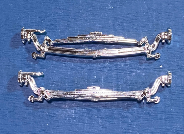
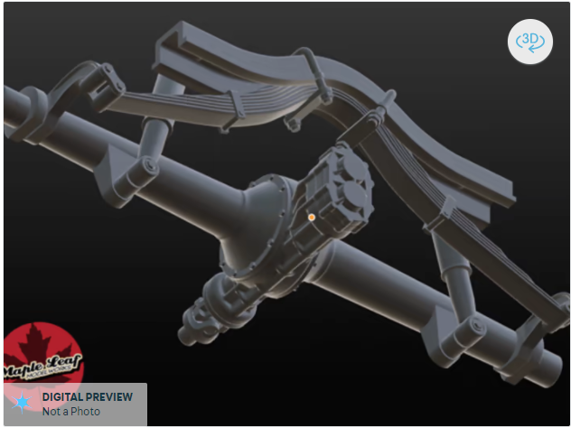
@Spex84 recently started offering one in his Shapeway store for anyone that's looking for one. He even designed a crossmember to go with it that is designed to drop into the new Revell Model A coupe or roadster kits
-
Question about an AMT single axle trailer
Mr. Metallic replied to VW93's topic in Model Building Questions and Answers
I could use them since Mr. Geiger passed on them? -
Very nicely done. You nailed the paint job. I received a set of the Mako specific parts from my good friend Chuck, and will combine that with the Enforcer version of this tooling to build mine.
-
Great color for the body. And thanks for sharing your faux-wood technique.
-
"Simple" Revell 30 Model A Coupe. finished 4/11/2022
Mr. Metallic replied to Mr. Metallic's topic in WIP: Model Cars
Get your motor running... Lets turn our attention to the engine. As much as it may pain some (especially Mr. Tim Boyd) I'm keeping the Chevy small block (SBC) in this one, for the sake of simplicity. Remember, that's how this whole project started, right? However, I'm going to do my best to backdate the SBC with traditional speed equipment. Let's get started. The headers that come in the kit are really nicely molded, with an open end which is quite a feat executed by Revell using the sliding mold technology. I just don't care for the shape of the bent tube exit. This is just my personal preference, so feel free to skip this step. First I trimmed the end off, sanded the flange flat, and then drilled a pilot hole in the center of the flange with a #70 drill bit. Then I progressed up though several sizes of drill bits, until the diameter of the hole is just slightly smaller than the diameter of the exhaust tube on the other side of the flange, taking care not to dill though the other side. Next we're going to pin the exhaust headers to the block to ease installation during final assembly. By now you know the drill, pun intended. Drill a hole through the flange that butts against the engine block into one of the exhaust pipes, Which ones you choose is up to you, but if you make your choices different on the left and right headers it will help you from accidently installing the wrong header on the wrong side of the engine. Drill gently and straight because those tubes are small. You don't have to go very deep, maybe 1mm, just enough to anchor the pin. Glue your pin in place, let glue dry, and then use the pin and ink method to mark your new hole location on the block. This method leaves no doubt that your header is in the right place and has a solid mount. Rather than the nicely done supercharged or 3 carb setups that come in the Revell kit I'm going to use the classic 6 carb intake that comes in the long running Revell Tweedy Pie kit (or any of it's variants issued over the last 50+ years). If you choose this setup you can use the carbs that Revell includes which are fine, but I had already stolen those carbs for a different project from my parts kit, so I chose to gather up 6 carbs from the Nailhead equipped versions of the modern Revell Model a kits. Trim the molded in mounting pins off the carbs and replace with metal pins. You can also take a moment and drill a hole in the side of the carb for eventual installation of a fuel line. Be sure to clean up the mold lines on the carbs too. At the top of the pic you can see the scoops I've chosen to use as well. these are 3D printed Cal Custom scoops from Maple Leaf Modelworks shop on Shapeways, which I also drilled a hole in the bottom to set atop the carbs during final assembly. This little scoops are beautiful, and feature an open mouth for added detail. @Spex84Once painted inside and chromed outside they're really going to pop. The Tweedy Pie intake drops right on the SBC block. I took the time to nip off the tall mounting point for the coolant hose at the front of the intake and drill it to accept a pin. I'll be using the beautifully done pre-wired distributor from Morgan Automotive Details on this build. Enlarge the hole for the kit supplied distributor to accept the MAD dizzy, and then place the intake on the block. Once you get the intake where you want it continue drilling that hole into the top of the block, that way you use the base of the distributor as the locating pin for the intake to the block. You can also drill holes into the center of all 6 of the inlet ports for the carbs on the top of the intake. Again, align the intake on the block and continue drilling those holes through the intake ports into the top of the block. Now it's ready to accept all 6 of your carbs. Finally it's time for a mockup. The only other mods I'll be making are using the stock style oil pan from the Tweedy Pie to replace the billet style kit supplied oil pan, and swapping the kit alternator for the short generator from the Tweedy Pie as well. It needs to be a short generator in order to use the kit supplied fan belt and water pump with molded in bracket for the generator, or else it will hit the front of the cylinder head. I also chopped off the automatic transmission to replace it with a manual transmission designed specifically for this block from Replicas and Miniatures of Md. A real hot rod has to have four pedals, right? Now, lets take a look at where we've landed with our alterations. -
Nice clean build of what can be a tough kit. Revell tried to provide max detail at the time, but made it tricky to get clean results sometimes. You nailed it.
-
Pro touring 70 1/2 Camaro (Dutchboys 2015 SEMA tribute)
Mr. Metallic replied to Steve H's topic in Model Cars
This thing came out so nice. It's a study in beautifully aggressive styling. You really did a great job. -
"Simple" Revell 30 Model A Coupe. finished 4/11/2022
Mr. Metallic replied to Mr. Metallic's topic in WIP: Model Cars
Body, louvers and a grille- It's time to pay some attention to the body. Revell's kit features a mildly chopped body. If you noticed in the mock ups I've decided to go a bit lower, using the further chopped roof from Altered States. I actually did the master for this chopped top 5-6 years ago when the first version of this kit came out. I also mastered an un-chopped body for it. Sadly, the owner of Altered States has been having health issues and has stopped casting. However, the changes I'm making to this top also apply to the top from the kit. The roof insert Revell decided to put in the kit is kind of a rare bird, not often seen on 1:1 Model A's, whether stock or hot rodded. The roof insert on the stock 1:1 30 Coupe bodies extends forward of what Revell created, all the way to the visor. Modifying the kit roof just requires a little time and some plastic. Lets give it a shot. First, take the kit supplied roof insert and lay it on top of a piece of sheet plastic. I used .020 Evergreen sheet. Use the straight factory edge of the plastic sheet to your advantage to create the squared off front edge of the stock roof insert by setting the kit insert back about 3mm from the edge. The distance is not critical, but leave it a little longer to allow you some excess to trim for exact fit. Trace the kit insert onto the sheet, but as you trace down the sides instead of following the curve around the front keep extending that line forward to the edge of the sheet (as seen here) Cut out the new top, keeping in mind that the piece you traced will be slightly larger than the original. You can compensate for that by cutting just inside the line, or cutting the line itself and then finessing the size with sanding sticks. Make the piece so it fits the existing hole in the roof, except for the front edge which we still need to cut out of the body. Once you are happy with the fit of your new part lay it on top of the roof to use as a template for modifying the opening in the roof. Trace around the front of your new piece. Then remove your roof insert and you'll see what material you need to remove. Remember, cut inside the line and then finesse with sanding sticks. While you're doing that go ahead and remove all the areas marked with red, which includes the lip detail around the inside since we will have to replace it. Leave the rear part of the lip for now to keep your insert from constantly falling through the hole as you do your multiple sand/fit/repeat trial fittings. If you are going to permanently attach your insert you don't need to remove the inner lip. Once you are happy with the new opening you have created give the new insert one last fit before you remove that rear lip. You can bend and tweak the contour of your insert to match the profile of the roof. Once you are happy with the fit you can add a bead detail around your roof insert with plastic strip, I used .020 x .020, one long piece for the sides/back. When you cut the piece for back/sides make sure you leave it long to allow for trimming at the front edge. Start applying the strip a little at a time along the rear edge and be sure to keep the strip straight and follow the edge of the insert. Work carefully around the corners and down the sides. A trick is to pre-bend the corner areas a bit by pulling the strip between your fingers with light pressure to introduce a curve to the strip. Once all the glue has dried, trim the ends of the strip flush with the front end, and then use a new piece across the front To give the insert a place to rest take strips of .030 x .100 strip and attach it to the underside of the roof to create a new lip. If you like you can omit the lip at the front edge because there is not a lot of space on the underside if the roof near the visor. Once that is done set your new insert in the roof and admire the results. Here's an technique I've been wanting to try for awhile, now seems like the perfect time. Archer makes some pretty cool detailing items for the model railroad part of the hobby, and this item in particular can be adapted to 1/25 scale. It is rows of resin louvers, applied to a very this clear decal, which makes applying them quite simple. I cut out 5 rows of louvers, soaked the paper for 10 second, let the glue loosen from the paper backer, and then carefully guided the decal onto the trunk. The clear decal is VERY thin so that the edge disappears under a coat of paint, but it also makes it prone to tearing, so use a light touch. The directions suggest using decal setting solution, but I would recommend that only as a last resort. Placing the decal and then hitting it with a little heat from a hair dryer (set on low) will really snuggle up that decal to the body. If you have any wrinkles you need to smooth out very carefully apply a small amount of setting solution with a small brush. But honestly most applications shouldn't require the setting solution. I used setting solution per the instructions and I really feel it made the decal tear more easily, and gave me some tense moments where three of the louvers separated from the rest. It took a few minutes with a toothpick gently maneuvering them back into place. And finally, the grille. The grille that Revell supplied looks good and can be used with just a little detail painting. However, it comes with molded in electric fan detail, which just won't stand for a traditional hot rod. I'll use this as an opportunity to upgrade. I'm using the piece from the Monogram Blue Bandito, the tooling for which has seen multiple revisions since it started as the Blue Beetle in the early 60's. You can use the rad/shell from any Model A kit you choose. To securely attach it to the frame I used my standard pin and hole method, drilling two small holes into the bottom of the radiator, and then inserting pins. To get the top of the radiator at the right level in comparison to the top of the cowl so it has a nice profile from the side I had to add a .080 x .080 plastic strip to the top of the front crossmember. Glue it in place, and I made the choice to add a little filler to make it all look like one piece. Drill matching holes in the top of the new strip to allow the radiator to pin on top of it. -
"Simple" Revell 30 Model A Coupe. finished 4/11/2022
Mr. Metallic replied to Mr. Metallic's topic in WIP: Model Cars
Thank you. Yes, the further chopped top is resin from Altered States. -
"Simple" Revell 30 Model A Coupe. finished 4/11/2022
Mr. Metallic replied to Mr. Metallic's topic in WIP: Model Cars
Interior- Not a ton of modifications happening here because Revell did a solid job with their interior straight out of the kit, just a few subtle things to help the overall appearance. There is always one thing that jumps out to me when I see these Revell Model A's built if it's not addressed. It's the notches in the sides of the interior where the side panels key into the floor. Those notches are highly visible from underneath. I started the process of addressing this earlier in the build buy making the floor pan sit flush on the frame. This helps hide those notches quite a bit, and you can stop there if you like, but I'm going a step further and just eliminating them altogether. First, select the size of plastic strip you will use to fill the gaps. It helps to select a size slightly larger than the notches themselves. Here is what you need, the floor, and 6 filler pieces. Enlarge the notches lightly to accept the strips. Cut the strips a little long to give you something to hold on to and allow for precise trimming later. Glue your fillers into the notches and let the glue cure. I also took this opportunity to fill the round holes for the crossmember. You may also note that I cut off the tail end of the floor pan to accommodate the new spring crossmember. This will be covered in a later installment. Trim the filler pieces flush with the floor, and then treat the areas with a little filler to blend them in. Then you're ready to prime. The extra holes in the rear axle have also been filled, and the mods to the K-member from a Revell 32 Ford kit have been completed. Now we can address the side panels. Revell made the interesting choice to mold the rear inner fenderwells in conjunction with the interior side panels. They are meant to be a part of the body, so lets make things easier on ourselves and just remove them and attach them to the body. Draw a straight line from the upper rear corner of the pleated interior down to just in front of the fenderwell. Sever the fenderwell insert and glue it to the body. We are going to fill this notch that ends up below the rear windows (arrows), so square up that opening to accept the styrene strip of your choice. You will want to pick a strip that will be flush or taller than the rest of the top of the panel so you can sand it flush. Also clip off the the tabs at the bottom marked with red X's. Here is why we are filling that notch below the back windows. It was probably made to allow space for the clear piece to fit there, but I'll be replacing these windows with acetate, so I don't need the room and this will look better. If you're going to use the kit glass here, omit this mod. The top panel in the pic has been hit with a little filler to the notch, and now has been fully modified and is ready for primer/paint. This is the extent I'll be going with modifications to the interior on this project, but the canvas Revell has provided is great for personalization, including seat swaps and adding detail. -
"Simple" Revell 30 Model A Coupe. finished 4/11/2022
Mr. Metallic replied to Mr. Metallic's topic in WIP: Model Cars
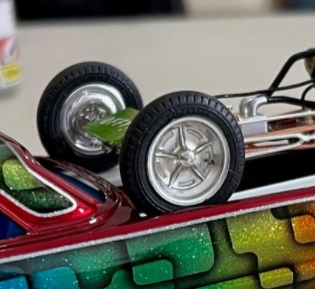
Ok, before I do another step in the build, here's the moment you've all been waiting for, the mock-up... yes, the body is shifted back slightly on the frame. This was a result of me being in a hurry ? The rear axle is also shifted back ? After working on this for a week I was just excited to see it up on 4 wheels finally -
I really want to build a version with that 4 cam motor, or at least put it in something. I have a minty Dream Rod kit that I of course want to build as the DR, but that means I'll have the 4 cam engine left over. I could always throw it in one of the Tiger Shark Toy Fair kits I got cheap at the Ertl store way back when.
-
"Simple" Revell 30 Model A Coupe. finished 4/11/2022
Mr. Metallic replied to Mr. Metallic's topic in WIP: Model Cars
Can you tell me which Shapeways store you found those wheels in please? I will say that I've seen a few of the 3d printed SCOT and Ardun parts around and they are nice, but the Replicas and miniatures Co of Md resin parts are still the best IMHO.