Chariots of Fire
-
Posts
2,781 -
Joined
-
Last visited
Content Type
Profiles
Forums
Events
Gallery
Everything posted by Chariots of Fire
-

Loadstar Brush Truck
Chariots of Fire replied to Chariots of Fire's topic in WIP: Model Trucks: Big Rigs and Heavy Equipment
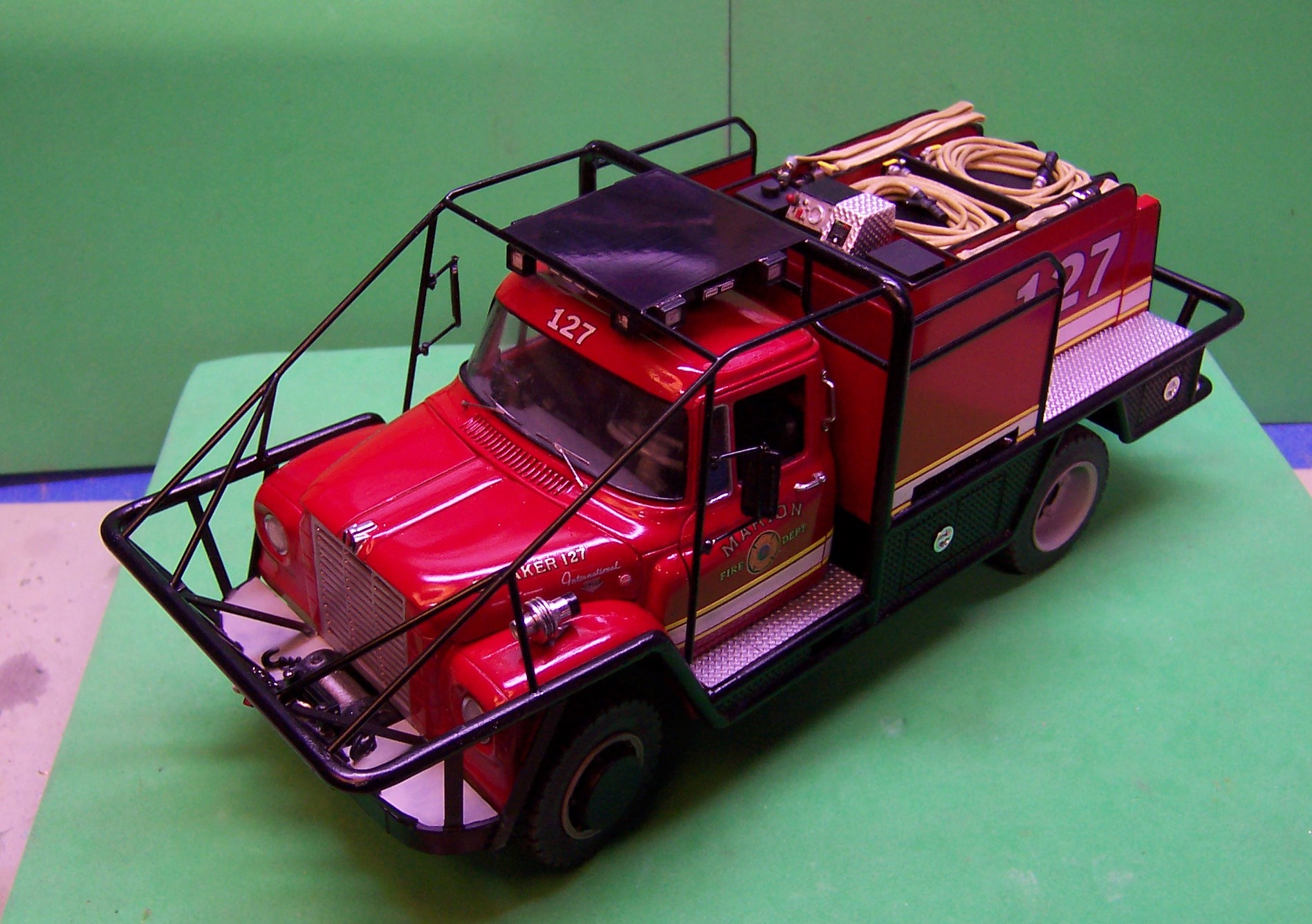
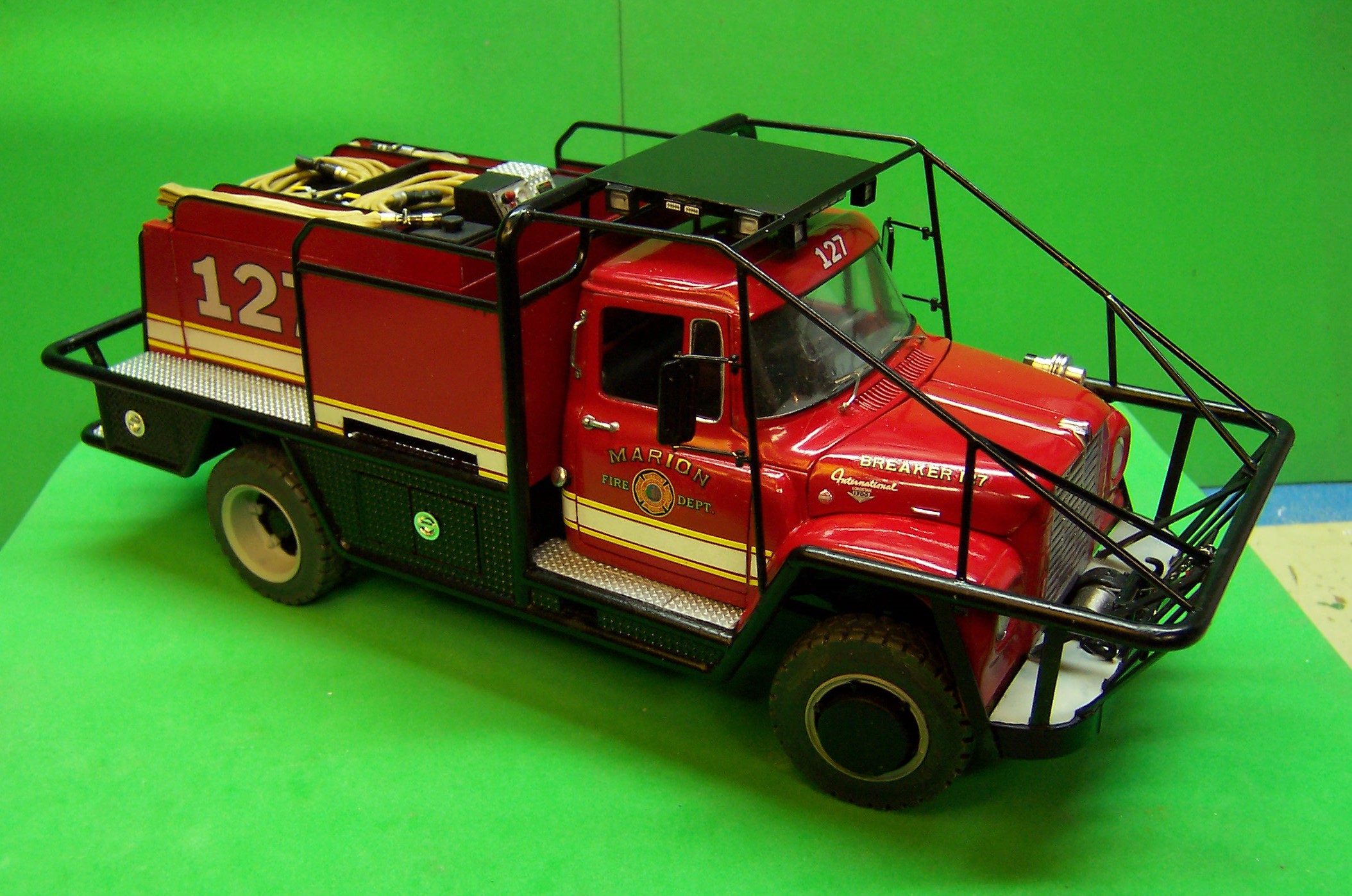
We are closing in on the last few details that will finish this build. Almost ready to fight some fire! Siren is turned aluminum. Lettering is taken from photos of the real truck, re-created on my computer, downsized and printed on the ALPS printer. The hose is sewing elastic that was stained with some acrylic tan watered down. Couplings are aluminum tubing. so are the gate valve handles. Still to go are two stutter horns for the front bumper, some led lights, hand tools and the license plates.
-
Maybe we should quit while we are ahead!
-
Glad to help out, Mike. Hope you find good size for the winch. The wire I used was 0.015". I'd recommend going with a slightly larger diameter, say 0.018" which is 0.46mm diameter.
-
Tom: Just a quick suggestion for the winch cable. Michaels craft store has some great mylar coated silver stranded bead wire that looks just like winch cable. I used some on my breaker model. I think they might have a larger size for use on your rig.
-
You want fries with that???
-
That last artwork is excellent! How will you finalize it?
-
Marmon 57P Conventional
Chariots of Fire replied to BlackDragon's topic in Model Trucks: Big Rigs and Heavy Equipment
Nicely done! It's amazing what the Molotow chrome does. One of the best modeling materials to come our way in a long time. Thanks for sharing! -
Loadstar Brush Truck
Chariots of Fire replied to Chariots of Fire's topic in WIP: Model Trucks: Big Rigs and Heavy Equipment
-
You are going to be one busy bee!!
-
Right on both accounts. The step can fold up out of the way. The spanners are for smaller hose sizes such as 1-1/2" and 2-1/2". Large diameter feeder hoses typically have quick connect couplings these days known as Storz couplings. European design that found its way to the US back in the 60's. Italeri had some European fire apparatus appliances and couplings in a nice little kit years ago. Probably can be found at model show vendor's tables at reasonable prices.
-
Loadstar Brush Truck
Chariots of Fire replied to Chariots of Fire's topic in WIP: Model Trucks: Big Rigs and Heavy Equipment
That's all scratch built based on photos and a few measurements of the actual piece. And yes we are on the other side of the hump but not exactly coasting yet. -
Anyone make a resin 1 ton dump bed
Chariots of Fire replied to fordf-100's topic in Truck Aftermarket / Resin / 3D Printed
Italeri used to make a detailing kit with those sorts of things. Unfortunately they were not very good. For landscaping you need rakes, long handle pointed shovels, brooms, trimmers, a couple of baskets for trimmings, a small lawnmower, all kinds of goodies. Some can be scratch built. Others not so easy. Try the websites that cater to G Guage railroad equipment. They have a good supply you could look through. G Guage is the same as 1/24 so it wouldn't be far off for scale. Only about 4%. -
Loadstar Brush Truck
Chariots of Fire replied to Chariots of Fire's topic in WIP: Model Trucks: Big Rigs and Heavy Equipment
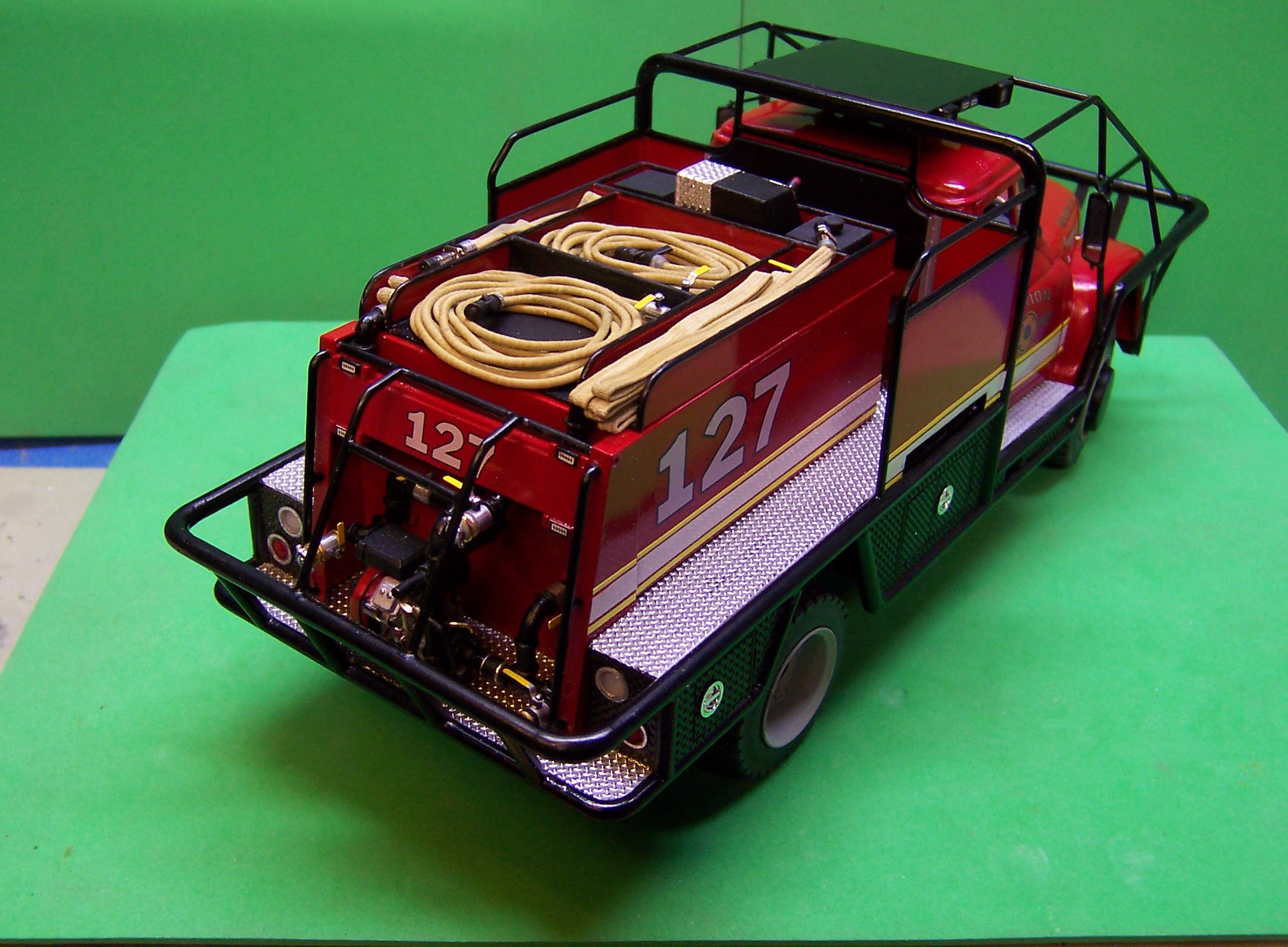
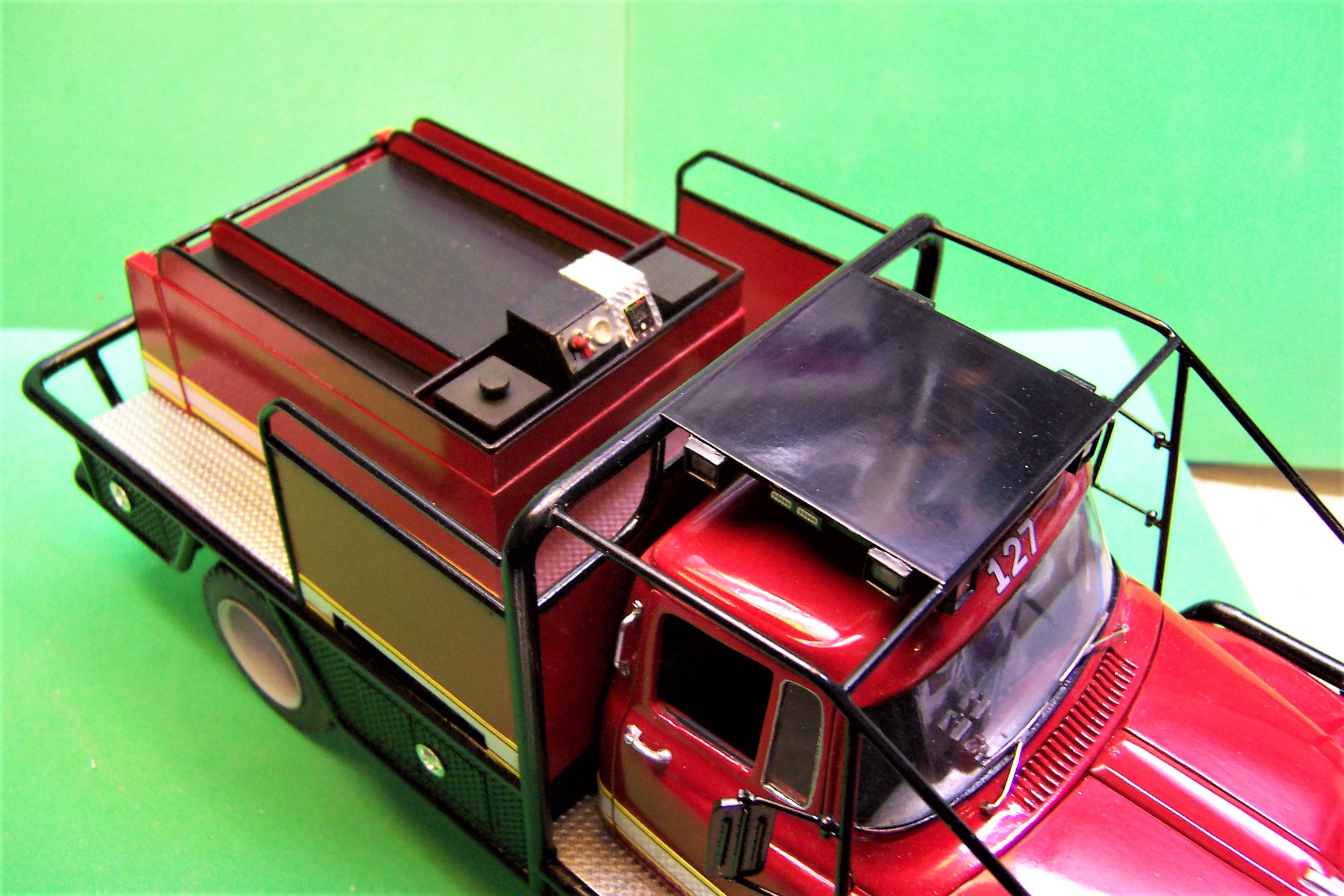
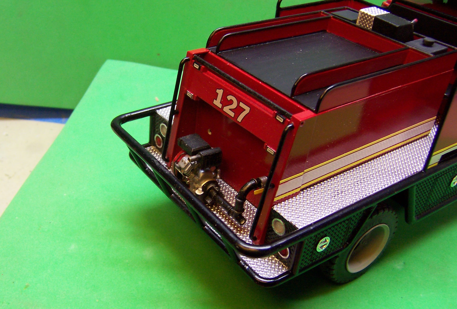
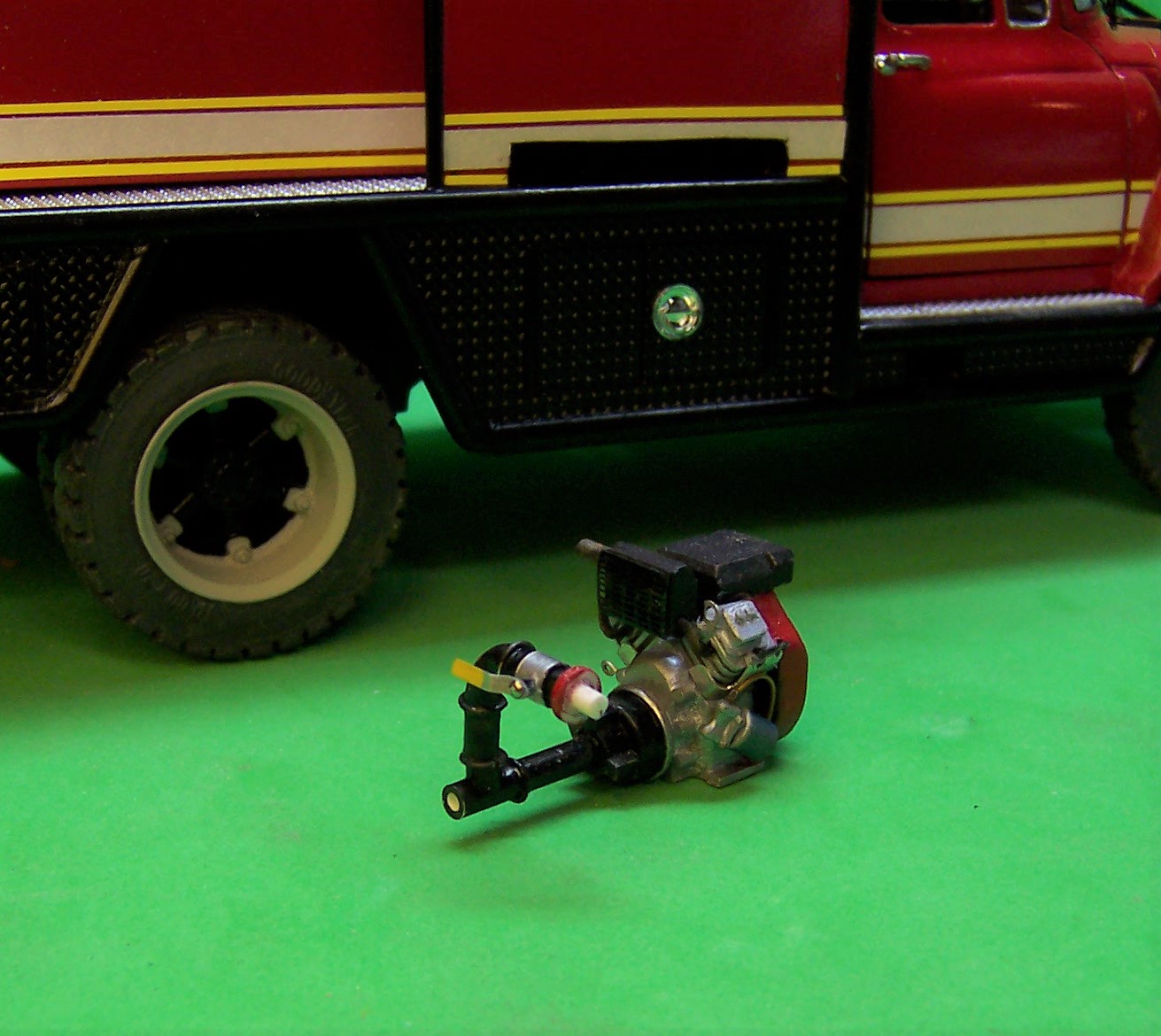
Here we go with some detailing. With the body complete now it's on to the stuff that makes the truck work. This rig was updated a few years ago with a new poly tank, foam system and new pump. While these are certainly not in keeping with the age of the IH, it works. These rigs get heavy use from time to time and then sit idle for long periods of time, being taken out only to keep things working properly. So we have a Honda V-twin engine powering a Hale centrifugal pump. Class A foam is now a routine feature for fighting natural cover fires. It acts as a wetting agent, reducing the amount of water it takes to put the fire out. Poly tanks also are a great feature in that they reduce weight and don't rust out. So here is where we are today. Control Panel and water and foam covers on top of the tank Pump on the rear step with just the beginning of all of the plumbing done. The winch cable is now secure with a clasp and hook. New NFPA regulations require all firefighters to be seated with responding to an alarm. They obviously never rode a brushbreaker! But the crew can at least enjoy the ride getting there. The Honda engine and Hale pump. And the back side. The pipe ends will eventually have other plumbing attached. We are just not there yet.
-
I say AMEN to that! It all takes time!
-
Anyone make a resin 1 ton dump bed
Chariots of Fire replied to fordf-100's topic in Truck Aftermarket / Resin / 3D Printed
Unless it's a real custom I'd go with a basic black body or maybe a dark gray. Lots of images of one ton dumps on line to choose from. -
Now you're clickin'! It's good to see some Imagineering at work! I was checking out your hood and hinges. Can I make a suggestion??? Either you are going to have to sand down the edge of the hood at the cowl OR you are going to have to take a wedge out of each side at the hinges to bring the hood in a bit. It looks to me like there is a bit of overhang at the cowl. Is there some overhang or is it just the way I'm looking at it?
-
International Sightliner
Chariots of Fire replied to dragstueck's topic in Model Trucks: Big Rigs and Heavy Equipment
That's by far the best weathering job I have ever seen! Not bad scratch building either! By chance did you omit the steps on the back of the fenders for cab entry? Just wondering how the driver gets in. -
ProStar Fleet Truck
Chariots of Fire replied to overbyja's topic in Model Trucks: Big Rigs and Heavy Equipment
Good lookin', Jake!! -
1/25 Studebaker Turbine Truck
Chariots of Fire replied to Casey's topic in WIP: Model Trucks: Big Rigs and Heavy Equipment
That's some nice work, Casey! I have made brass springs before and it time consuming but very rewarding in the end. -
Loadstar Brush Truck
Chariots of Fire replied to Chariots of Fire's topic in WIP: Model Trucks: Big Rigs and Heavy Equipment
I use 90 degree bends from Plastruct. The larger ones had to be sanded down to fit the tubing I used. The 1/8" diameter tubing has bends of the same size. Some sections that were less than 90 had to be trimmed by hand. -
Loadstar Brush Truck
Chariots of Fire replied to Chariots of Fire's topic in WIP: Model Trucks: Big Rigs and Heavy Equipment
Thanks, Vince. It will be a while longer. There's a pump and plumbing still for the back, some additional decals, a siren and a hose load still to be done. -
Anyone make a resin 1 ton dump bed
Chariots of Fire replied to fordf-100's topic in Truck Aftermarket / Resin / 3D Printed
I agree. That looks good and in the right proportions for the cab. Add some small pieces of sheet stock to the front and rear top of the sides leaving space for the side boards and it will be complete! -
Moebius 4x4 Ford
Chariots of Fire replied to bill lanfear's topic in WIP: Model Trucks: Pickups, Vans, SUVs, Light Commercial
That's a nice "old" build! Thanks for sharing your progress. I got some tips along the way! -
International resin cabs?
Chariots of Fire replied to highwayman58's topic in Truck Aftermarket / Resin / 3D Printed
Sort of like this one? This one has a resin hood and fenders blended to two Ertl Cabs. The most difficult part of the match was getting rid of the dip in the top of the cab so that it was flat from front to rear.
-
What sort of details did you add that you were not sure of the purpose of? Maybe I can help with that. I was a firefighter/Station Captain for 44 years.